Cisco Secure Firewall Threat Defense SD-WAN Design and Deployment Guide
Available Languages
Bias-Free Language
The documentation set for this product strives to use bias-free language. For the purposes of this documentation set, bias-free is defined as language that does not imply discrimination based on age, disability, gender, racial identity, ethnic identity, sexual orientation, socioeconomic status, and intersectionality. Exceptions may be present in the documentation due to language that is hardcoded in the user interfaces of the product software, language used based on RFP documentation, or language that is used by a referenced third-party product. Learn more about how Cisco is using Inclusive Language.
- US/Canada 800-553-2447
- Worldwide Support Phone Numbers
- All Tools
 Feedback
 Feedback
Overview of Cisco Secure Firewall SD-WAN Solution
This document offers a pre-validated design and deployment guide for Cisco SD-WAN using Cisco Secure Firewall Threat Defense and Cisco Secure Firewall Management Center. It covers design guidelines, configurations, and considerations for building a highly available, full-service SD-WAN network, and directs readers to best practices for Cisco SD-WAN with Secure Firewall.
Software-Defined WAN (SD-WAN) solutions offer a modern approach to wide area networking by enabling flexible connectivity across various WAN transport technologies. SD-WAN allows for dynamic, policy-based application path selection over multiple WAN connections and facilitates integration with additional services such as WAN optimization and firewalls.
As organizations expand their operations across multiple branch locations, ensuring secure and streamlined connectivity becomes paramount. Deploying a secure branch network infrastructure involves complex configurations, which can be time-consuming and prone to configuration errors if not handled properly. However, organizations can overcome these challenges by leveraging the Cisco Secure Firewall Management Center (Management Center) and the Cisco Secure Firewall Threat Defense (Threat Defense) devices for a simplified and secure branch deployment.
In this guide, we explore how to simplify secure branch deployment using a robust firewall solution. By integrating a secure firewall as a foundational component of the branch network architecture, organizations can establish a strong security baseline while simplifying the deployment process. This approach enables organizations to enforce unified security policies, optimize traffic routing, and ensure resilient connectivity.
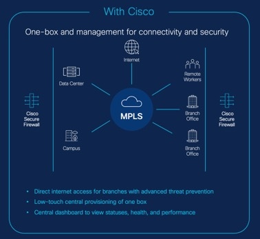
Cisco Secure Firewall SD-WAN Capabilities
● Secure Elastic Connectivity:
◦ Route-based Virtual Tunnel Interfaces (VTI) VPN tunnels between headquarters (hub) and branches (spokes)
◦ IPv4 and IPv6 BGP, IPv4 and IPv6 OSPF, and IPv4 EIGRP over VTI
◦ Dynamic VTI (DVTI) hubs that support spokes with static or dynamic IP
● Simplified management:
◦ Zero touch provisioning of SD-WAN devices
◦ Device templates for simplified branch deployments
◦ SD-WAN wizard for VPN tunnel setup between centralized headquarters and remote branches
◦ Centralized SD-WAN dashboard for monitoring SD-WAN network, application visibility, and performance monitoring
◦ SSE Integration for SASE deployment
● Application awareness:
◦ Direct Internet Access (DIA) for public cloud and guest user
◦ Policy based routing (PBR) using applications as a match criteria
◦ Local tunnel ID support for Umbrella
● Increased usable bandwidth:
◦ ECMP support for load balancing across multiple ISPs and VTIs
◦ Application-based load balancing using PBR
● High availability with near zero network downtime:
◦ Dual ISP configuration
◦ Optimal path selection based on application-based interface monitoring.
Cisco Secure Firewall SD-WAN Features
The table lists the SD-WAN features in Management Center:
Table 1. SD-WAN features in Management Center
| Feature |
Introduced In |
| SD-WAN Wizard |
Release 7.6 |
| Application monitoring using SD-WAN Summary dashboard |
Release 7.4.1 |
| SD-WAN Summary Dashboard |
Release 7.4 |
| Policy-based routing with user identity and SGTs |
Release 7.4 |
| Policy-based routing using HTTP path monitoring |
Release 7.4 |
| Loopback interface support for VTIs |
Release 7.3 |
| Support for dynamic VTI (DVTI) with site-to-site VPN |
Release 7.3 |
| Umbrella auto tunnel |
Release 7.3 |
| Support for IPv4 and IPv6 BGP, IPv4 and IPv6 OSPF, and IPv4 EIGRP for VTIs |
Release 7.3 |
| Route-based site-to-site VPN with hub and spoke topology |
Release 7.2 |
| Policy-based routing with path monitoring |
Release 7.2 |
| Site to Site VPN Monitoring Dashboard |
Release 7.1 |
| Direct Internet Access/Policy Based Routing |
Release 7.1 |
| Equal-Cost-Multi-Path (ECMP) zone with WAN and VTI interfaces |
Release 7.1 |
| Backup VTI for route-based site-to-site VPN |
Release 7.0 |
| Support for static VTI (SVTI) with site-to-site VPN |
Release 6.7 |
SD-WAN Architecture with Management Center and Threat Defense Devices
The information in this document is based on these software versions:
● Cisco Secure Firewall Management Center Release 7.6
● Cisco Secure Firewall Threat Defense Release 7.6
Refer to the architecture diagram as a reference for this deployment guide:

● New York City, NY (NYC): Primary SD-WAN hub with a Firewall 3105 HA pair (NYC-FW-HA)
● Newark, NY (NNJ): Secondary SD-WAN hub with a Firewall 3105 HA pair (NNJ-FW-HA)
● ISP1 and ISP2: All hubs and branch devices are connected to these two service providers
● Providence, RI (PRI): SD-WAN branch with Firepower 1010 (PRI-FW-01)
● Worchester, MA (WMA): SD-WAN branch with Firepower 1120 (WMA-FW-01)
● New Haven, CT (NCT): SD-WAN branch with a Firepower 1120 HA pair (NCT-FW-HA)
● Manchester, CT (MCT): SD-WAN branch with Threat Defense Virtual (MCT-FW-01)
● Management Center Virtual: Manages all the hubs and branch devices.
● Security Cloud Control (SCC): Cisco’s unified, cloud-native security management interface for the Cisco Security Cloud that facilitates Zero Touch Provisioning (ZTP) and other cloud assist features.
The hubs use:
● Dedicated management interfaces to communicate with the Management Center.
● Data interfaces to connect with the branch Threat Defense devices.
Table 2. IP Addresses of Hubs and Spokes
| Device |
Inside Network |
| New York City, NY (NYC) |
10.100.0.0/16 |
| Newark, NY (NNJ) |
10.200.0.0/16 |
| Providence, RI (PRI) |
10.71.0.0/16 |
| Worchester, MA (WMA) |
10.72.0.0/16 |
| New Haven, CT (NCT) |
10.73.0.0/16 |
| Manchester, CT (MCT) |
10.74.0.0/16 |
Onboard Threat Defense Device to Management Center
Design and Configuration Guidelines
● Zero-Touch Provisioning (ZTP) method:
◦ Uses serial numbers of the Threat Defense devices
◦ Supports only these device models:
- Firepower 1010
- Firepower 1100
- Secure Firewall 1200
- Firepower 2100 (7.4.x only)
- Secure Firewall 3100
◦ Integrates your Management Center with Security Cloud Control
● Registration key method:
◦ Uses registration key of the Threat Defense devices
◦ Supports all device types, including Threat Defense virtual devices
◦ Works with or without device templates
Device Onboarding Methods
You can onboard your SD-WAN Threat Defense devices to the Management Center in multiple ways:
● Serial Number: Use ZTP to onboard one or more devices using their serial numbers. See Onboard Threat Defense Device to Management Center Using ZTP.
● Registration Key: Onboard a single device by specifying the registration key and defining variables in the Management Center. See Onboard Threat Defense Device to Management Center Using Registration Key.
Overview of Threat Defense VPN Tunnel Interfaces
The VPN tunnel interface is a logical interface that interconnects the underlying network (underlay) and the virtual overlay network. It securely transmits overlay traffic through tunnels. This interface is a fundamental component of SD-WAN tunnel connectivity and supports both IPv4 and IPv6 traffic.
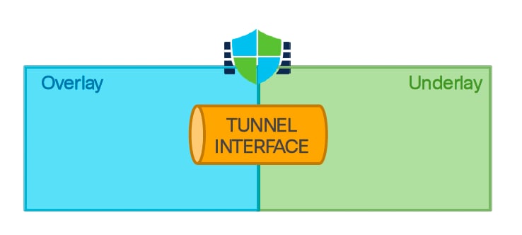
Threat Defense IPsec Virtual Tunnel Interface
Threat Defense supports Virtual Tunnel Interfaces (VTIs), which are routable logical interfaces. You can use these interfaces to apply static and dynamic routing policies. VTIs simplify VPN configuration by eliminating the need for static crypto map access lists and tracking remote subnets. They enable route-based IPsec VPNs, where the threat defense device encrypts or decrypts traffic based on routing table entries. VTIs support static and dynamic routes, but not multicast.
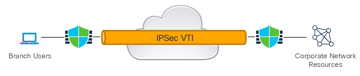
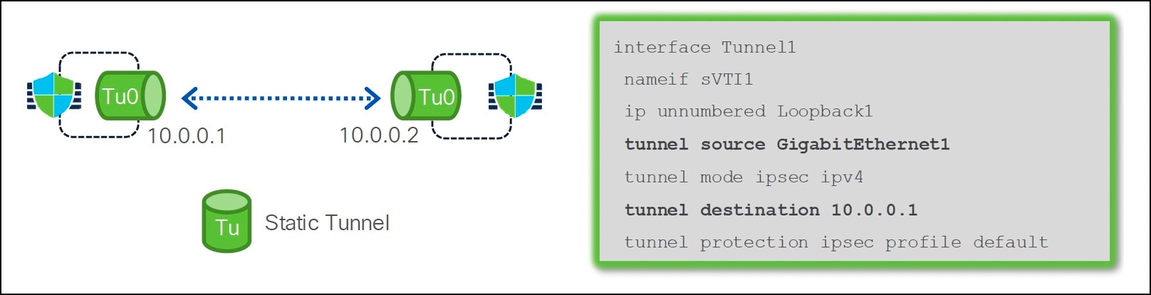
Static Virtual Tunnel Interface
A static Virtual Tunnel Interface (SVTI) is a type of routable virtual interface used to establish site-to-site IPsec VPN tunnels introduced in Version 6.7. These interfaces establish always-on, bidirectional IPsec VPN tunnels, allowing either connected device to initiate the connection. Using these interfaces, you can create tunnels between two Threat Defense devices or between a Threat Defense and other Cisco or third-party devices.
Dynamic Virtual Tunnel Interface
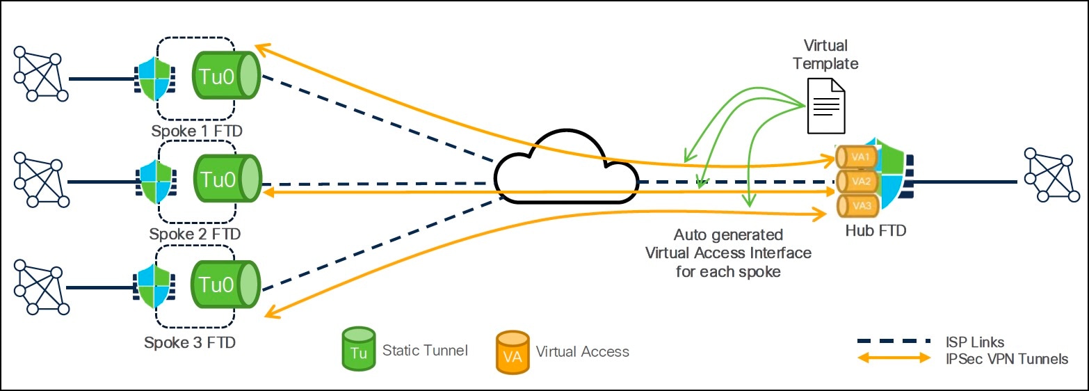
Dynamic VTI, introduced in Version 7.3, is a virtual tunnel interface for point-to-multipoint VPNs. It uses a virtual template for dynamic instantiation and management of IPsec tunnel interfaces. The virtual template dynamically generates a unique virtual access interface for each VPN session. Dynamic VTI supports multiple IPsec security associations and accepts multiple IPsec selectors proposed by the spoke. This interface is unidirectional, where only spokes can initiate the tunnel establishment connection.
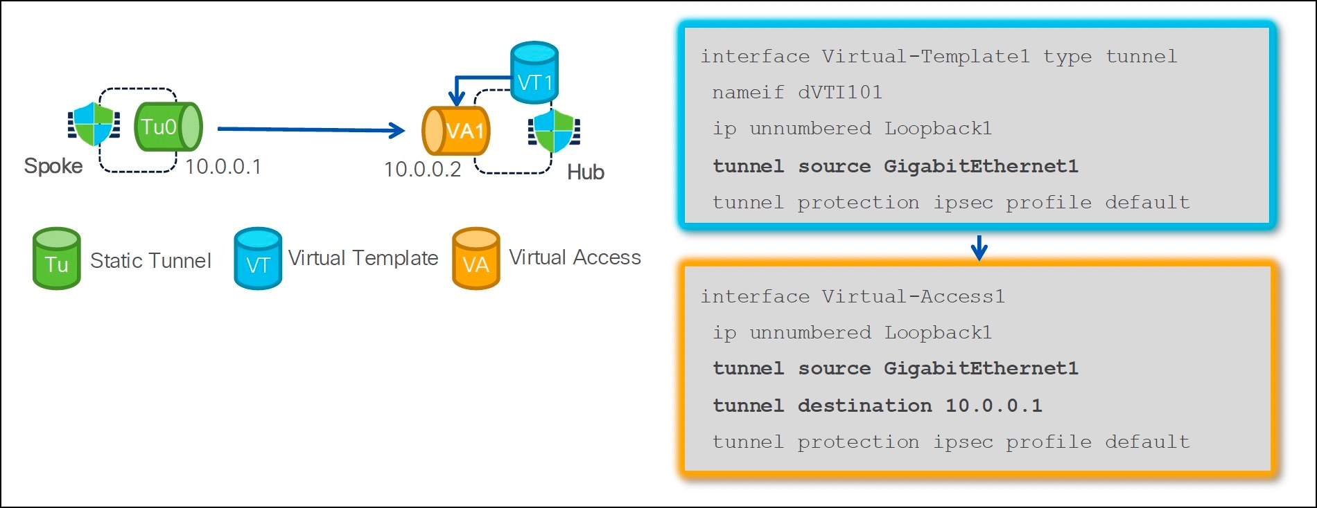
In a hub-and-spoke deployment, when a spoke device initiates a connection to the hub, the hub utilizes the virtual template to create a unique virtual access interface for each spoke.
Deploy an SD-WAN Overlay Using Cisco Secure Firewall Management Center
Establishing a secure network infrastructure connecting remote branches to the central headquarters is challenging. Manually configuring and deploying these devices within an SD-WAN topology is time-intensive and error-prone, potentially leading to inconsistencies in network settings and security vulnerabilities across different locations.
Management Center allows you to easily configure VPN tunnels and routing configuration between your centralized headquarters (hubs) and remote branch sites (spokes) using the new SD-WAN wizard. This wizard automatically configures route-based VPN tunnels with Dynamic Virtual Tunnel Interfaces (DVTIs) on the hubs and SVTIs (Static Virtual Tunnel Interfaces) on the spokes, along with BGP configuration of the overlay network.
For details on the workflow, and configuration of an SD-WAN overlay using the Management Center’s SD-WAN wizard, see Deploy an SD-WAN Overlay Using Cisco Secure Firewall Management Center.
Route Application Traffic Using Direct Internet Access
This section provides information for routing application traffic using Direct Internet Access (DIA).
Challenges with Traditional Networks
Traditionally, network deployments use a perimeter firewall at a central site to provide secure access for both local and branch users. While this architecture delivers the required connectivity, it routes all internet traffic through the central site via an encrypted VPN tunnel. This approach can lead to increased packet latency, drops, and jitter. Additionally, it often results in higher costs, greater bandwidth consumption, and more complex network management.
Overview of Direct Internet Access
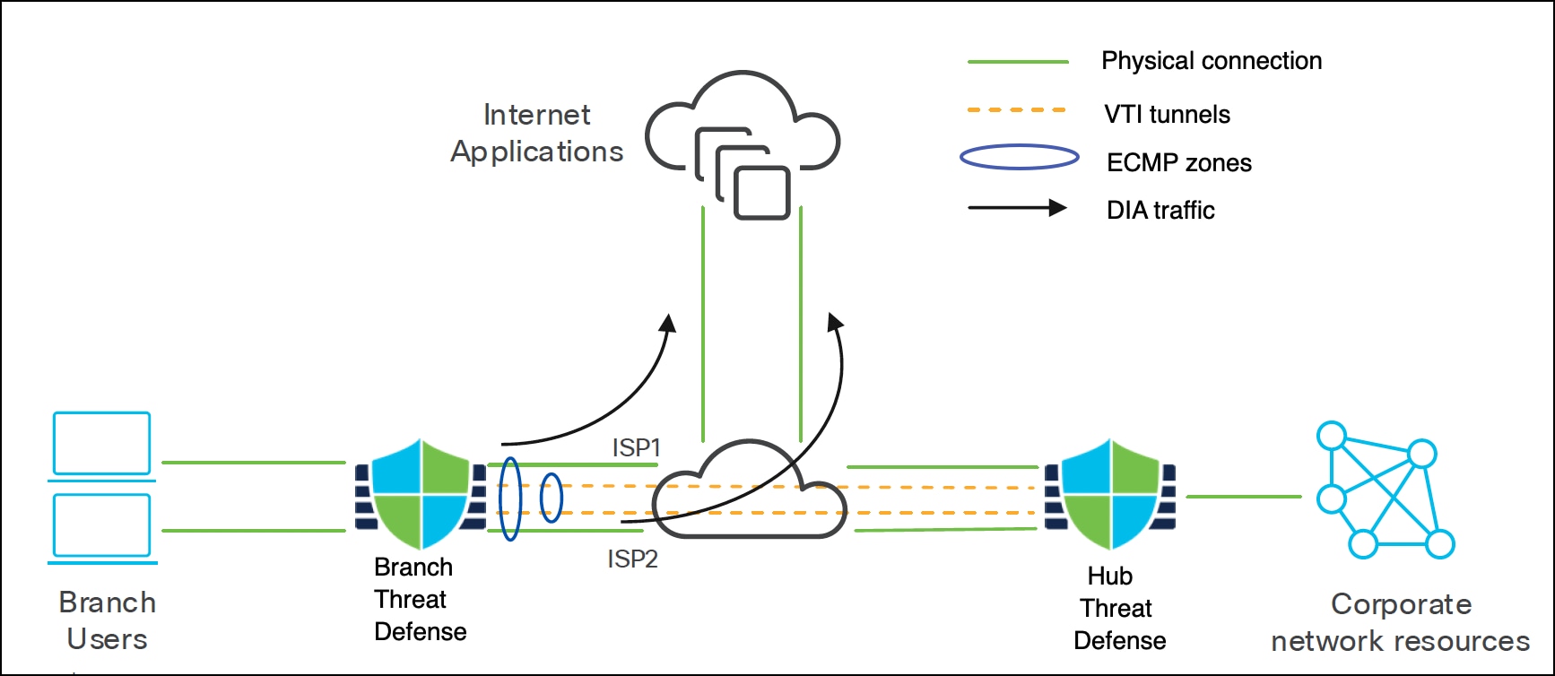
One way to address the challenges of traditional networks is to implement Direct Internet Access (DIA). DIA is a key SD-WAN feature available with Cisco Secure Firewall. It leverages Policy-Based Routing (PBR) and is also known as application-aware routing.
With DIA, application traffic from the branch office is routed directly to the internet, bypassing the need to tunnel internet-bound traffic through the headquarters. This feature reduces latency and enhances user experience. The branch Firewall Threat Defense device is set up with an internet exit point. A PBR policy is applied to the ingress interface to identify traffic based on attributes such as network, port, username, user groups, applications, and security group tags (SGTs) defined in an extended access control list. The identified traffic is then forwarded through the egress interfaces directly to the internet.
The different ways of steering traffic using PBR are:
● Source IP address-based routing (Version 7.1 and later)
● Application-aware routing (Version 7.1 and later)
● Application-aware routing with path monitoring
◦ IP-based (Version 7.2 and later)
◦ HTTP-based (Version 7.4 and later)
● Identity-based routing (AD user, user group and SGT) (Version 7.4 and later)
Types of Policy-Based Routing
Application-Aware Routing
Threat Defense device directly sends traffic to the internet based on the application.
The user workflow of application-aware routing with Management Center is:
1. User initiates a DNS request for one or more applications to one of the trusted DNS servers.
2. Threat Defense device snoops the DNS response and stores the domain information and their corresponding IP addresses.
3. Application traffic is directed to the egress interface based on the interface ordering in the PBR policy.
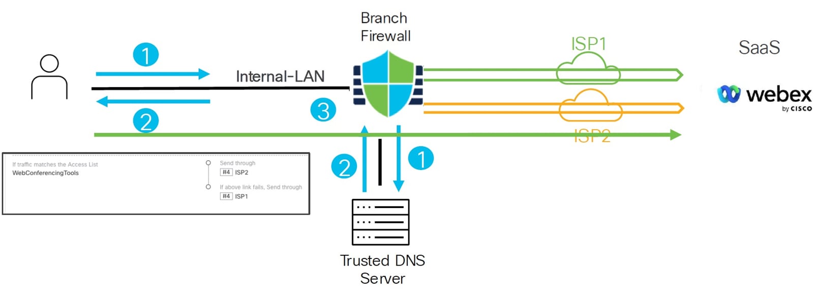
In this example, the PBR policy directs web conference application traffic such as Webex through the ISP2 interface, with automatic fallback to ISP1 if ISP2 fails.
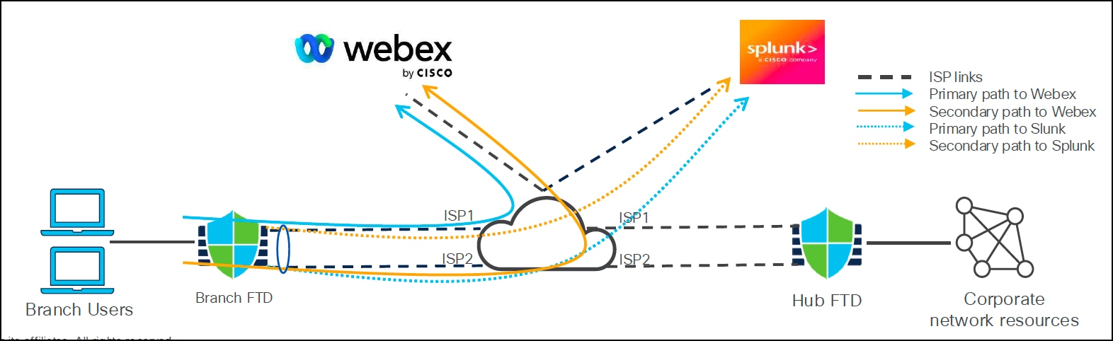
Application-aware Routing with Path Monitoring
Threat Defense device evaluates real-time metrics and sends application-aware traffic to the internet through the best calculated path. For interfaces configured with path monitoring, the Threat Defense device derives these metrics using ICMP or HTTP probes and determines the best path for routing traffic.
The dynamic metrics used for path monitoring are:
● Round trip time (RTT)
● Jitter
● Mean opinion score (MOS)
● Packet loss
In this example, the best path for Webex and Splunk applications is dynamically selected based on the path monitoring metrics.
Components of IP-based Path Monitoring
● Path Monitoring Module (PMM): Collects metrics using ICMP probes.
● Policy-Based Routing (PBR) Engine: Routes traffic through an egress interface according to the best metric from PMM.
The interface monitoring probe interval using ICMP is one second.
Architecture of IP-based Path Monitoring
The workflow of application-aware routing with IP-based path monitoring in Management Center is:
1. PMM sends ICMP probes to the monitored destinations.
2. PMM computes and stores interface metrics in the database.
3. PMM provides the list of interfaces with updates to PBR engine.
4. PBR engine fetches the latest metrics from the PMM database.
5. PBR engine pushes the routing updates to the data path based on the interfaces and metrics.
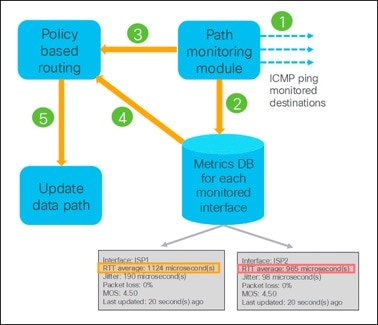
In this example, because the RTT of the ISP2 interface is lower than that of ISP1, the PBR engine receives this metric and directs traffic through the ISP2 interface.
Components of HTTP-based Path Monitoring
● HTTP Client: Sends HTTP probes to the monitored domains or applications and forwards the response back to PMM.
● Path Monitoring Module: Computes and stores the metrics through ICMP or HTTP probes
● Policy-Based Routing Engine: Routes the traffic through an egress interface according to the best metric from the PMM.
The application monitoring probe interval is 10 seconds.
Architecture of HTTP-based Path Monitoring
The workflow of application-aware routing with HTTP-based path monitoring in Management Center is:
1. HTTP client module will start application monitoring when a DNS entry is snooped for a given domain.
2. PMM computes and stores interface metrics in the database.
3. PMM provides the metric values per domain and egress interfaces to PBR engine every 30 seconds.
4. PBR engine pushes the routing updates to the data path based on the interfaces and metrics.
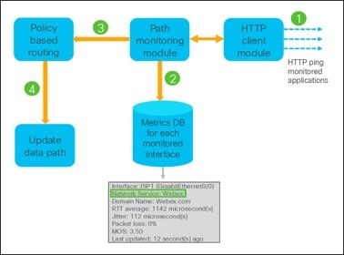
Note: The green highlighted section shows how the HTTP client module collects path metrics for Webex application traffic through the ISP1 interface.
The user workflow of application-aware routing with HTTP-based path monitoring is:
1. User initiates a DNS request for one or more applications.
2. Threat Defense device snoops the DNS response and stores the domain information and their corresponding IP addresses.
3. HTTP client module sends HTTP probes to the configured applications on egress interfaces with path monitoring enabled.
Note: By default, HTTP-based application monitoring is enabled for an interface.
4. PMM computes and stores the metrics for each interface and shares them with the PBR engine.
5. Application traffic is directed to the egress interface based on the best metric.
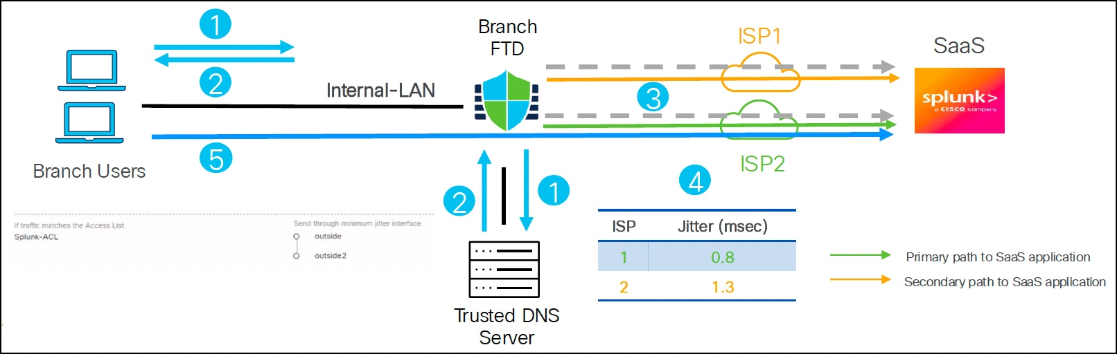
In this example, the PBR policy routes Splunk application traffic through the interface (outside or outside2) with the minimum jitter.
Identity-aware Routing
Identity-aware routing on a Threat Defense device extends application-aware routing by routing network traffic based on attributes such as:
● User identity
● Microsoft Active Directory (AD) groups
● Security Group Tags (SGTs)
This feature enables traffic segmentation based on user identities or SGTs, allowing differentiated access for employees, contractors, guests, and IoT devices. Integration with Microsoft AD is required and Cisco Identity Services Engine (ISE) is optional. If ISE is not integrated, you can configure SGTs locally in the Management Center.
Note: You cannot use Cisco ISE and local SGTs at the same time.
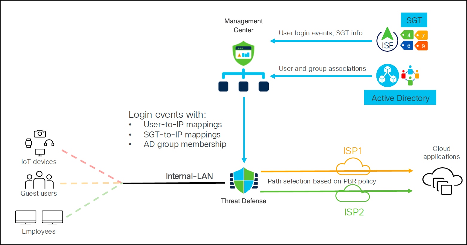
Management Center receives information such as:
● User login events and SGTs from ISE, the identity and access server.
● User and the group associations from AD server.
This information is used to create the PBR rules to allow traffic through egress interfaces based on the user identity, user group, or SGT.
Equal-Cost Multi-Path (ECMP)
You can configure ECMP from the Management Center UI from Version 7.0. It enables network traffic to be sent over multiple equal-cost paths. ECMP supports both physical and VTI interfaces and can have up to 8 interfaces within a zone.
Components for Direct Internet Access
● Trusted DNS Server: Application detection in DIA relies on DNS snooping through trusted DNS servers to resolve applications or a group of applications.
● Vulnerability Database (VDB): Threat Defense device gets the list of domains associated with applications from VDB for application detection.
● Network Service Object (NSO): Object associated with a particular application that is used within PBR. NSOs are predefined and the Management Center deploys them to the Threat Defense device.
● Network Service Group (NSG): Group of applications that the Threat Defense device uses to determine the path based on the PBR configuration. Multiple NSOs can be part of a single NSG. Management Center auto-generates NSGs based on the PBR extended access lists.
Order of Operations for Policy-Based Routing
1. Threat Defense device evaluates packets against the PBR policy in a top-down order.
2. PBR engine uses the egress interface based on the first match.
3. New entries are added to the bottom of the PBR policy.
Tech tip: If you have a complex PBR policy, ensure that you configure the most specific rules at the top.
4. Entries can be reordered by dragging and dropping to the desired sequence.
5. PBR engine falls back to normal routing if no match is found.
Note: PBR works on top of normal routing so ensure that the routes through different interfaces are available on the device even if they are not part of the active routing table.
Configure Direct Internet Access
For details on the workflow, configuration, and verification of DIA on Management Center, see Route Application Traffic to the Internet Using DIA in Cisco Secure Firewall Management Center.
Integrate SASE and SSE Solutions with Threat Defense
As more people work remotely and use cloud applications, traditional security models focused on data centers are less effective and can slow down users. Secure Access Service Edge (SASE) is a new approach that brings network and security services closer to users and devices, using the cloud. SASE helps users securely access applications and data from anywhere. SASE combines software-defined wide area networking (SD-WAN) and various security services, all delivered from the cloud. This allows organizations to connect any user or device to any application safely, without needing to manage complex infrastructure.
If a business wants to improve security without changing its whole network, Security Service Edge (SSE) is a good option. SSE delivers important security functions from the cloud, making security simpler and improving the user experience. Key SSE features include DNS-layer security, secure web gateway (SWG), firewall as a service (FWaaS), cloud access security broker (CASB), and zero trust network access (ZTNA). SSE is the security part of the SASE framework and can be used on its own or as a first step toward a full SASE setup that also includes networking features.
What is SASE and SSE?
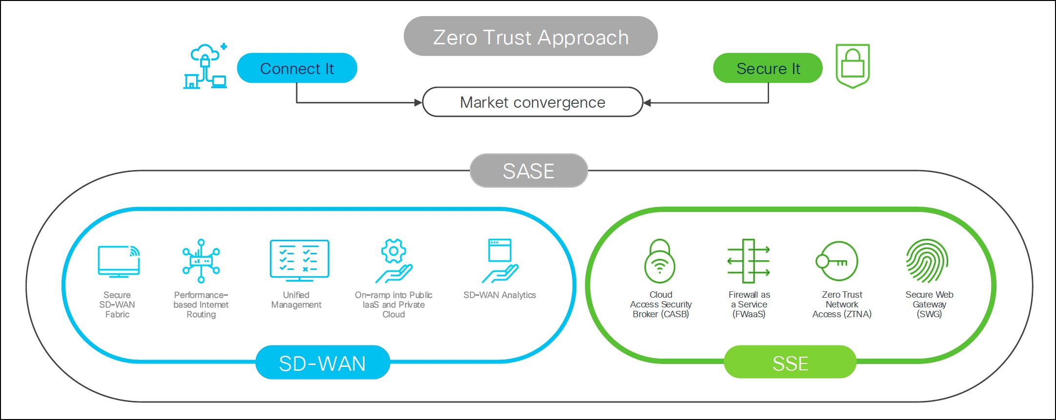
● Secure Access Service Edge (SASE):
◦ Integrates networking (SD-WAN) and security (SSE) capabilities.
◦ Encompasses security capabilities such as Secure Web Gateway (SWG), Cloud Access Security Broker (CASB), Data Loss Prevention (DLP), Next Generation Firewall (NGFW), and Zero Trust Network Access (ZTNA), combined with networking capabilities such as SD-WAN.
◦ Enables zero trust access based on device or entity identity, real-time context, and security and compliance policies.
◦ Cisco solution is Cisco SD-WAN (Catalyst, Meraki, Threat Defense) along with Cisco Umbrella and Cisco Secure Access.
● Security Service Edge (SSE):
◦ Focuses specifically on the security aspect of SASE.
◦ Secures access to the web, cloud services and private applications.
◦ Encompasses capabilities such as access control, threat protection, data security, security monitoring, and acceptable-use control enforced by network-based and API-based integration.
◦ Delivers cloud-based service, and can include on-premises or agent-based components.
◦ Cisco solution is Cisco Secure Access.
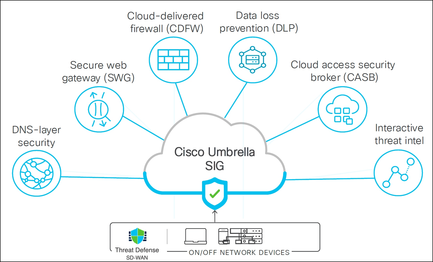
Cisco SASE Solution: Secure Internet Traffic Using Cisco Umbrella and Threat Defense
Cisco Umbrella is a cloud-based secure internet gateway platform that provides multi-layered protection against internet threats. It integrates DNS layer security, SWG, cloud-delivered firewall, DLP, CASB, and threat intelligence to deliver highly scalable security for all branches. Internet-bound traffic from remote or on-prem users is automatically routed from the branches to the nearest Umbrella point of presence for inspection before access is granted or denied.
Umbrella Integration Use Cases
Cisco Firewall can integrate with Umbrella in two ways:
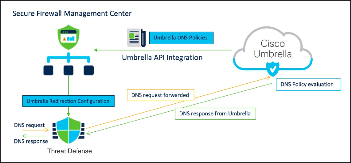
● Secure internet traffic for all branches with a consistent DNS policy.
◦ Common DNS policies for all branches
◦ Multi-layered DNS security (Management Center and Umbrella DNS policies)
◦ Secures users and applications at the DNS layer before any connections are established thus reducing consequent packet processing resulting in faster protection.
◦ Provides uniform DNS policy for hybrid workers
● Secure internet traffic for all branches using Umbrella auto tunnel.
◦ Implements the SASE solution
◦ Automatically configures tunnel on Threat Defense and Umbrella
◦ Provides uniform DNS control policies and web policy inspection for hybrid workers
◦ Improved internet performance (Internet traffic is routed to Umbrella
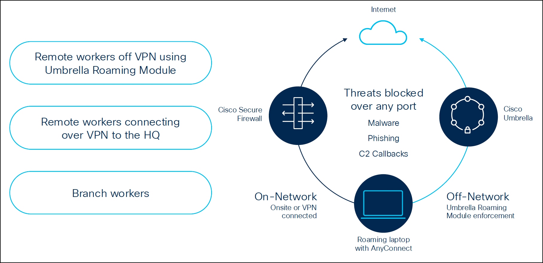
Common Security Policy Stack
The common security policy stack is designed to ensure that users receive consistent security protection, regardless of their location: on-premises or connected through VPN to a Threat Defense device. If the user is remote, Cisco Umbrella provides DNS and web policy inspection for these users through its roaming module. If the user is behind a branch firewall or connected via VPN, same policies can be enforced for consistent security.
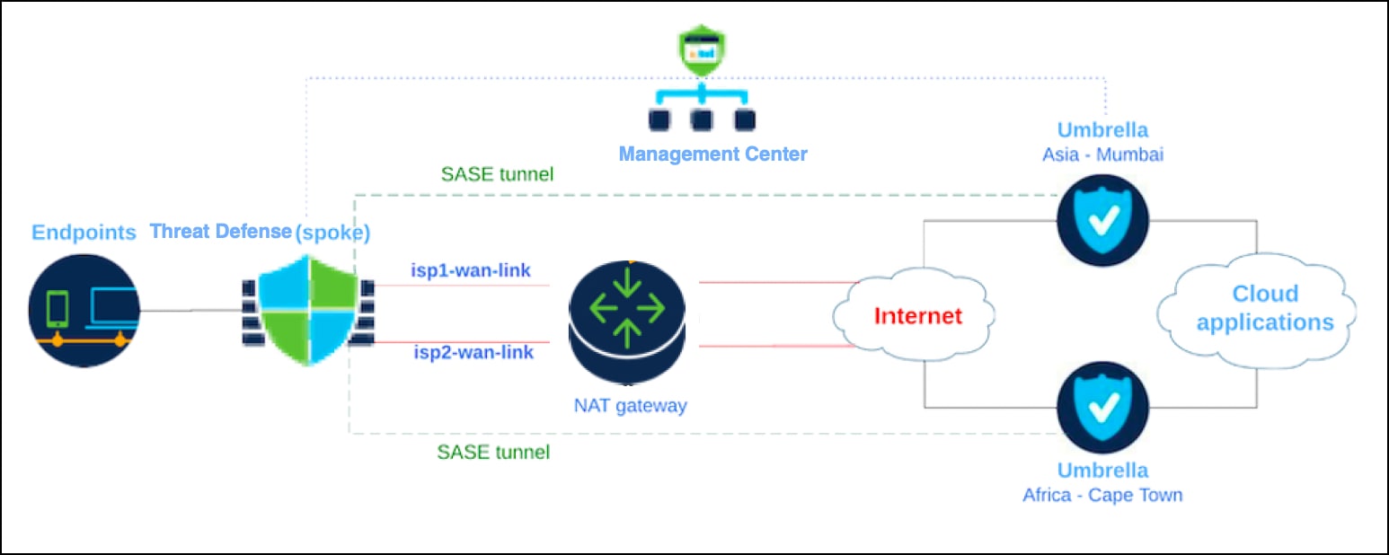
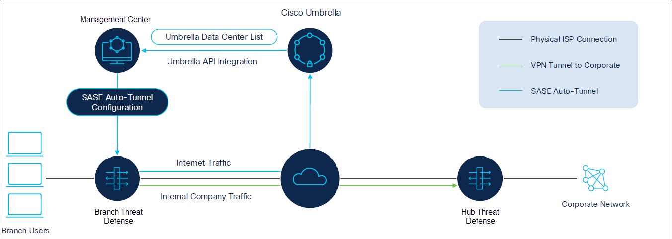
Secure Internet Traffic Using Cisco Umbrella Auto Tunnel with Threat Defense
Management Center enables automatic tunnel configuration for seamless integration with Umbrella Secure Internet Gateway (SIG). This integration allows network devices to forward DNS and web traffic to Umbrella SIG for inspection and filtering using the SIG tunnel.
With an intuitive, step-by-step wizard, Management Center streamlines the tunnel setup process and reduces the configuration required on both the Threat Defense device and Umbrella. By utilizing Umbrella APIs, it retrieves the list of Umbrella data centers and configures network tunnels using the parameters specified in the Umbrella Connection settings within Management Center.
Establishing a network tunnel between the Threat Defense device and Umbrella ensures consistent enforcement of DNS and web policies for both on-premises and roaming users.
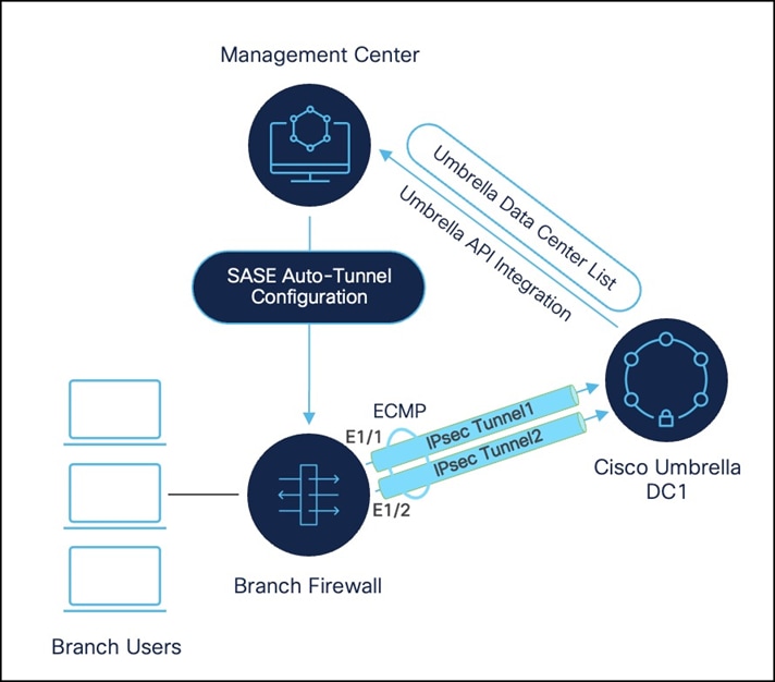
High Availability for Umbrella Auto Tunnel with Threat Defense Device
You can achieve high availability for Umbrella auto tunnel with a Threat Defense device in two ways:
1. High availability is achieved on the firewall.
You can configure up to eight active tunnels to a single Umbrella data center for active/active high availability. This ECMP-based setup provides redundancy and increased bandwidth.
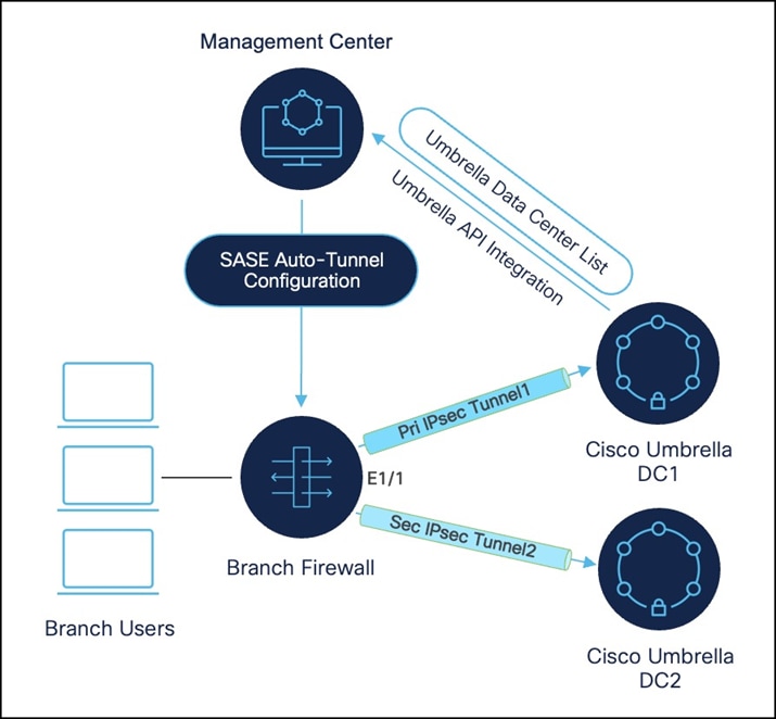
2. High availability is achieved using different Umbrella data centers.
You can configure up to eight active and eight backup tunnels to each Umbrella data center for active/backup high availability. This setup ensures protection against Cisco Umbrella headend failure.
Configure Umbrella SASE Auto Tunnel
For details on the workflow, prerequisites, configuration, and verification of Umbrella SASE Auto Tunnel on Management Center, see Secure Internet Traffic Using Cisco Umbrella and Threat Defense.
Cisco SSE Solution: Secure Internet Traffic Using Cisco Secure Access and Threat Defense
Secure Access is Cisco's cloud-based platform that provides you with multiple levels of defense against internet-based threats. Connect securely to the internet, SaaS apps, and your private digital resources, whether you connect from your organization's network or roaming off a network.
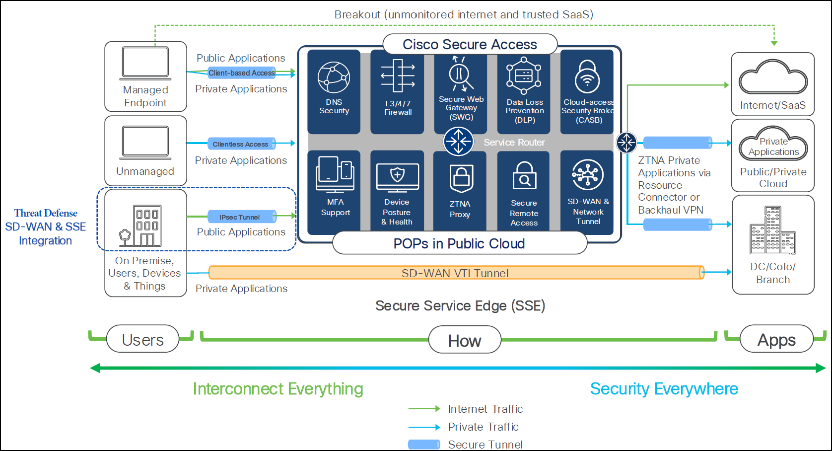
It is designed to provide users and endpoints, whether managed or unmanaged, with secure access to resources and applications, regardless of their hosting location (on-premise, data center, or private cloud). Cisco Secure Access functions as an infrastructure that delivers both connectivity and security. It incorporates various security capabilities crucial for modern networks, including:
● Client-based Access (Managed Endpoints): It is designed for devices managed by your organization. A client is installed on the endpoint to establish a secure, persistent connection to Cisco Secure Access.
● Clientless Access: It provides secure access for unmanaged devices (for example, personal devices, partner access) without requiring client installation.
● Public Applications: This includes general internet access and trusted Software-as-a-Service (SaaS) applications.
● Private Applications: These can reside in diverse locations, including On-premise data centers, public or private clouds, and branch offices.
Integrated Security Services
● DNS Security: Protects against malicious domains and command-and-control callbacks.
● L3/4/7 Firewall: Provides granular network and application layer traffic filtering and policy enforcement.
● Secure Web Gateway (SWG): Filters web content, enforces acceptable use policies, and protects against web-based threats.
● Data Loss Prevention (DLP): Prevents sensitive data from leaving the organization's control, whether through web, cloud, or endpoint channels.
● Cloud-access Security Broker (CASB): Extends security policies to cloud applications, ensuring compliance and data protection for SaaS and IaaS environments.
● Device Posture & Health: Assesses the security compliance and health of connecting devices before granting access, ensuring only trusted devices can connect.
● ZTNA Proxy: Enables secure, least privileged access to private applications without exposing them directly to the network.
● Secure Remote Access: Provides secure connectivity for remote users to use corporate resources.
● POPs in Public Cloud: Cisco Secure Access functions from strategically positioned Points of Presence (POPs) within public cloud environments, guaranteeing low-latency access worldwide.
● Tenant controls for Microsoft and Google services: Provides ability to specify and manage which Microsoft and Google tenants users can access, enhancing security and compliance
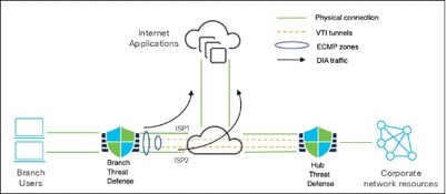
Threat Defense SD-WAN Branch Secure Internet Access (SIA) Architecture
In this example, the topology illustrates the foundational architecture for securing internet access at a branch office using Threat Defense and SD-WAN, integrated with Cisco Secure Access.
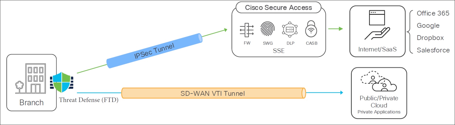
For the "Threat Defense SD-WAN Branch Secure Internet Access (SIA) Architecture", consider the following details:
● Branch Office: Represents the user's local network where the Threat Defense device is deployed.
● Threat Defense: Acts as the security gateway at the branch. It establishes a manual IPsec tunnel to Cisco Secure Access for the Secure Internet Access (SIA) use case.
● SD-WAN VTI Tunnel: The SIA traffic specifically uses a manual IPsec tunnel from the Threat Defense device to Cisco Secure Access.
● Cisco Secure Access: This is Cisco's Security Service Edge platform, providing various security functions in the cloud. Within this architecture, it incorporates:
◦ FW (Firewall): Basic network filtering.
◦ SWG (Secure Web Gateway): Protects against web-based threats and enforces web policies.
◦ DLP (Data Loss Prevention): Prevents sensitive data from leaving the organization's control.
◦ CASB (Cloud Access Security Broker): Extends security policies to cloud applications.
◦ SSE (Security Service Edge): The overarching cloud-delivered security framework.
● Internet/SaaS resources: Represents public internet resources and Software-as-a-Service applications like Office 365, Google, Dropbox, and Salesforce, which are accessed securely through Cisco Secure Access.
● Public/Private Cloud Private Applications: Indicates that private applications hosted in public or private clouds can also be accessed.
The "branch secure internet access use case" involves leveraging SD-WAN Virtual Tunnel Interface (VTI) VPN tunnels that extend from the branch to either a public cloud or a head-end location. These SD-WAN VTI tunnels are designed to coexist with other network configurations. The primary purpose of this IPsec tunnel is to provide secure access for your branch to web applications or other resources, whether they are hosted in the cloud or on-premises.
Currently, these IPsec tunnels are configured manually. Traffic redirection for these tunnels is managed using policy-based routing (PBR), a method similar to what is observed with Umbrella.
Threat Defense SD-WAN Branch Secure Internet Access Traffic Flow
This topology details the precise path and security capabilities applied to traffic originating from the branch office and destined for the internet or SaaS applications through Cisco Secure Access.
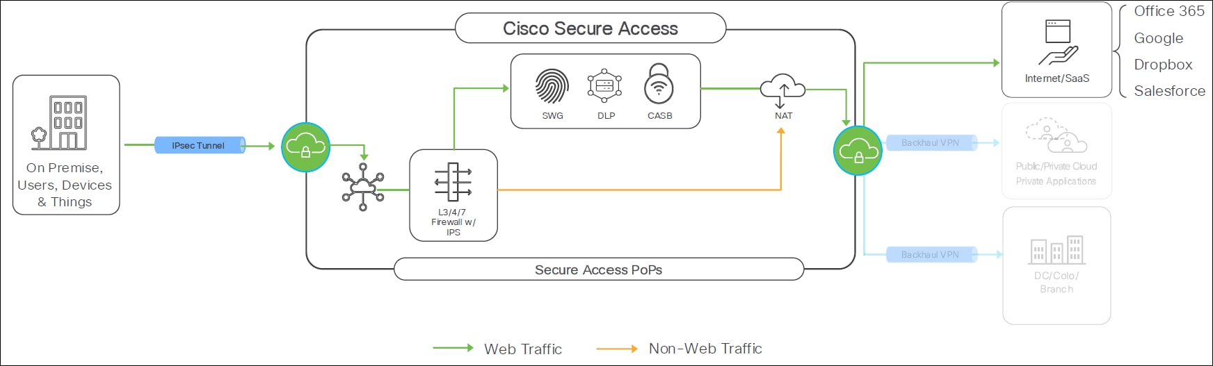
Tunnel Setup:
● Tunnel Configuration: You can configure these tunnels in either an active-active or active-backup design.
● Bandwidth: Each tunnel from the firewall to Secure Access supports up to 1 Gbps.
● Scalability: To achieve bandwidth beyond 1 Gbps, ECMP (Equal-Cost Multi-Path) can be used.
● Supported Scenarios: This setup also supports overlapping and outbound NAT scenarios.
Here are the key components of traffic flow for Secure Internet Access (SIA) from a Threat Defense SD-WAN Branch, covering both web and non-web traffic:
● On-Premise Setup: The secure firewall on-premise establishes an IPsec tunnel to Cisco Secure Access Intra.
● Destination: This tunnel leads traffic towards the internet or SaaS applications.
Threat Defense SD-WAN Branch Secure Internet Access High Availability (HA)
This section details how high availability (HA) is achieved for Threat Defense SD-WAN Branch Secure Internet Access (SIA) deployments, ensuring continuous secure internet access even in the event of component failures or datacenter outages.
High availability in this integration is provided through two primary types of redundancy:
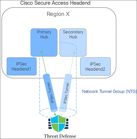
1. Cisco Secure Access Headend Redundancy
The Cisco Secure Access Headend is designed with redundancy to ensure continuous service.
● Mechanism: A branch Threat Defense device is configured to connect to both a Primary hub and a Secondary hub within the Cisco Secure Access region. This is facilitated by the Network Tunnel Group (NTG) concept, which allows a remote site to establish two tunnels to Cisco Secure Access. If Primary Hub fails, connectivity will be maintained through Secondary Hub.
● Components:
◦ Cisco Secure Access Headend (Region X): The cloud-based infrastructure for Cisco Secure Access, deployed across different regions.
◦ Network Tunnel Group (NTG): A logical grouping of IPsec headends that provides redundancy.
◦ IPSec Headend1 (Primary Hub): The primary datacenter or point of presence (PoP) that the Threat Defense device actively uses for the IPsec tunnel.
◦ IPSec Headend2 (Secondary Hub): The secondary or backup datacenter/PoP, ready to take over if the primary becomes unavailable.
● Switchover Conditions: The system automatically switches from the primary to the secondary hub in the following scenarios:
◦ Data Center (DC) offline: If the primary datacenter is taken offline for maintenance or other planned reasons.
◦ Data Center (DC) outage: In the event of an unplanned disruption or failure of the primary datacenter.
● Benefit: This redundancy ensures that branch users maintain connectivity to the internet and private resources, regardless of the primary datacenter's operational status.
2. Threat Defense (Firewall) Side Redundancy
Redundancy is also implemented on the Threat Defense (firewall) side, allowing for resilient tunnel connectivity.
● Tunnel Configurations: The Threat Defense can be configured with two types of tunnel redundancy:
◦ Active/Backup Tunnels: One tunnel is active and used for all outbound and inbound traffic, while the other serves as a standby.
◦ Active/Active Tunnels: Multiple tunnels are active simultaneously, leveraging Equal-Cost Multi-Path (ECMP) for both outbound and inbound traffic. This configuration supports up to 16 tunnels (8 active + 8 backup as maximum 8 interfaces are supported in an ECMP zone).
● Switchover Mechanisms: The FTD uses the following methods to switch traffic between tunnels:
● IKE Dead Peer Detection (DPD) for Static Routing: If static routing is used, IKE DPD monitors the liveness of the IPsec tunnel peer. If the primary peer becomes unresponsive (dead), the FTD automatically switches the tunnel to the secondary hub.
● BGP (Border Gateway Protocol) Timer: For dynamic routing, BGP is used to advertise reachability information. If the BGP peering on the primary path goes down, the Threat Defense pivots to the next BGP pair, routing traffic over the secondary tunnel to connect to the Cisco Secure Access.
Integrate Cisco Secure Access with Threat Defense Devices for Branch Network Security
For details on the workflow, prerequisites, configuration, and verification of the Secure Access integration with Threat Defense devices, see Secure Branch Using Cisco Secure Access and Threat Defense.
Conclusion
This comprehensive guide demonstrates how to build a highly available and secure SD-WAN network leveraging Cisco Secure Firewall Threat Defense and Management Center. From streamlined device onboarding and wizard-driven SD-WAN topology creation to advanced routing redistribution and intelligent Direct Internet Access (DIA) with Policy-Based Routing (PBR), the document encompasses end-to-end deployment. It emphasizes the strategic integration of Cisco Umbrella and Cisco Secure Access for SASE/SSE, delivering robust, cloud-native security, traffic steering based on application and identity, and high availability for a truly modern and protected branch environment.
Authors
Dinesh Moudgil, Technical Leader - TME
Rashmy Abraham, Content Designer
Sunilkumar Hegade, Content Designer