Onboard Cisco Secure Firewall Threat Defense Device to Cisco Secure Firewall Management Center
Available Languages
Bias-Free Language
The documentation set for this product strives to use bias-free language. For the purposes of this documentation set, bias-free is defined as language that does not imply discrimination based on age, disability, gender, racial identity, ethnic identity, sexual orientation, socioeconomic status, and intersectionality. Exceptions may be present in the documentation due to language that is hardcoded in the user interfaces of the product software, language used based on RFP documentation, or language that is used by a referenced third-party product. Learn more about how Cisco is using Inclusive Language.
- US/Canada 800-553-2447
- Worldwide Support Phone Numbers
- All Tools
 Feedback
 Feedback
Onboard Threat Defense Device to Management Center Using Zero-Touch Provisioning
You can register devices to the Management Center using Zero-Touch Provisioning (ZTP). This method is used to onboard a single Threat Defense device using a serial number without performing any initial setup on the device.
Network Topology
Here’s the network topology diagram.
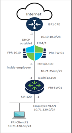
In this example, we onboard a Firepower 1010 Threat Defense device to the Management Center using ZTP. This device is a spoke in the Providence, RI (PRI) branch of the SD-WAN network.
● Threat Defense Model: Firepower 1010
● Device Name: PRI-FW-01
● Loopback IP address: 10.71.255.1/32
● Eth1/1: Outside interface connected to ISP1 and uses DHCP.
● Eth1/8.100: Inside sub-interface connected to the LAN network.
● Serial Number: FJC57213ZDZ
● PRI-SW01: Layer 3 device that connects the Threat Defense device to the LAN.
Prerequisites for Onboarding Threat Defense Devices Using ZTP
● Ensure that the device is unconfigured or a fresh install. Zero-Touch Provisioning is meant for new devices only. Pre-configuration can disable zero-touch provisioning, depending on how you configure the device.
● Cable the outside interface of the device so it can reach the internet.
● Ensure that the Threat Defense device can connect to Cisco Security Cloud and Management Center.
● Ensure that the Management Center is registered to the Smart Software Manager. A valid evaluation license is sufficient, but if it expires, you will not be able to add new devices until you successfully register.
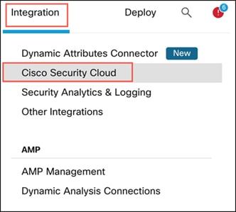
● Integrate Management Center with Cisco Security Cloud: Security Cloud Control onboards the on-prem Management Center after you integrate it with Cisco Security Cloud. We need this integration to onboard Threat Defense device using zero-touch provisioning.
i. In the Management Center, choose Integration > Cisco Security Cloud.
ii. Click Enable Cisco Security Cloud to open a separate browser tab to log you into your Cisco Security Cloud account and confirm the displayed code. If you have multiple tenants, choose the tenant to which the management center must be onboarded.
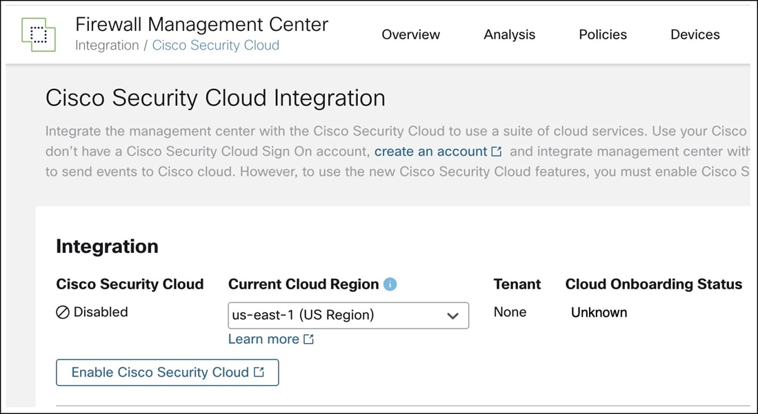
iii. Check the Enable Zero-Touch Provisioning check box. If required, review and enable other options such as Policy Analyzer and Optimizer, Cisco XDR Automation, Cisco Security Cloud Support, and Cisco AI Assistant for Security.
iv. Click Save.
Prerequisites for Using Device Templates
● Management Center must be Version 7.6 or later.
● Threat Defense devices must be Version 7.4.1 or later and must be one of these models:
◦ Firepower 1010
◦ Firepower 1100
◦ Secure Firewall 1200
◦ Firepower 2100
◦ Secure Firewall 3100
● Only Admin and Network Admin users can create, modify, or delete templates.
● License entitlements for the target device must be present in the Smart Licensing account.
Create a Device Template
Step 1. Choose Devices > Template Management.
Step 2. Click Add Device Template.
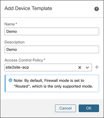
Step 3. In the Add Device Template dialog box, configure these parameters:
i. In the Name field, enter the name for the template. In this example, the template name is Demo.
ii. (Optional) In the Description field, enter a description for the template.
iii. From the Access Control Policy drop-down list, choose an access control policy.
Step 4. Click OK.
Configure a Template for Threat Defense Devices Managed Using the Data Interface
Note: You cannot apply a template configured for Threat Defense devices managed using the data interface on devices that are not managed by the data interface.
Step 1. Choose Devices > Template Management.
Step 2. Click the Edit icon of the required template (Demo).
Step 3. Click the Template Settings tab.
Step 4. In the General tile, toggle the Manage device by Data Interface button.
Step 5. A popup is displayed that asks you to pick a data interface for manager access. Click OK.
Step 6. Click the Interfaces tab.
Step 7. Click the Edit icon of the data interface that you want to use for manager access.
Step 8. In this example, Ethernet1/1 is the data interface.
Step 9. In the Edit Physical Interface dialog box, click the General tab.
Step 10. In the Name field, enter the name for the interface.
Step 11. In this example, the name is outside1.
Step 12. (Optional) In the Description field, enter a description for the interface.
Step 13. Check the Enabled check box.
Step 14. From the Security Zone drop-down list, choose a security zone.
In this example, the security zone is outside-zone.
Step 15. Click the IPv4 tab.
Step 16. From the IP Type drop-down list, choose Use DHCP.
Step 17. Click the Path Monitoring tab.
Step 18. Check the Enable IP based Monitoring check box.
Step 19. Click the Manager Access tab.
Step 20. Check the Enable management access check box.
Step 21. Click Save.
Add a Physical Interface in the Template
By default, a device template enables the device to come up with the following physical interfaces:
● Management interface 0/0
● Inside interface (Ethernet 1/1)
● Outside interface (Ethernet 1/2)
In this example, we are not using the default Ethernet1/2. We will create a physical interface, Ethernet1/8.
Step 1. Choose Devices > Template Management.
Step 2. Click the Edit icon of the template in which you want to add the physical interface (Demo).
Step 3. Click the Interfaces tab.
Step 4. Click Add Physical Interface.
Step 5. From the Slot drop-down list, choose 1.
Step 6. From the Port Index drop-down list, choose 8.
Step 7. Click Create Interface.
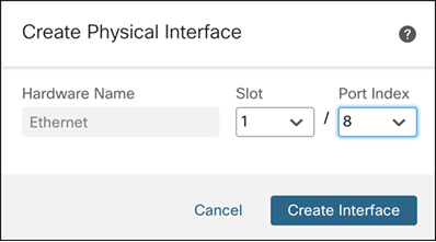
Edit this interface to configure its Name as inside-trunk, and Description as Inside trunk interface to LAN.
Create a Sub Interface for an Interface in the Template
In this example, Ethernet1/8.100 is the inside sub-interface connected to the LAN network.
Step 1. Choose Devices > Template Management.
Step 2. Click the Edit icon of the template in which you want to add the physical interface (Demo).
Step 3. Click the Interfaces tab.
Step 4. Click Add Interfaces > Sub Interface.
Step 5. In the Name and Description fields, enter the details.
Step 6. Check the Enabled check box.
Step 7. From the Security Zone drop-down list, choose a security zone.
In this example, the security zone is inside-zone.
Step 8. From the Interface drop-down list, choose an interface.
Step 9. In the Sub-Interface ID, enter 100.
Step 10. In the VLAN ID, enter 100.
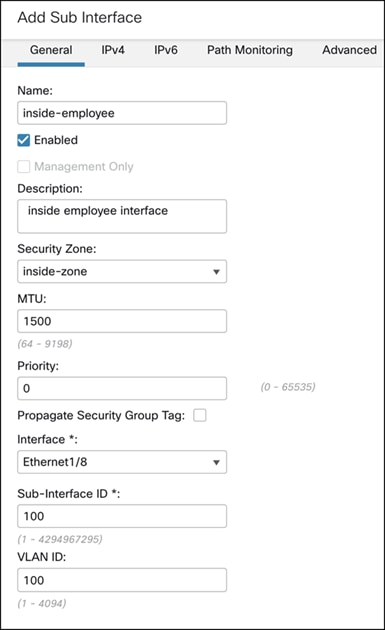
Step 11. Click the IPv4 tab.
Step 12. From the IP Type drop-down list, choose Use Static IP.
Step 13. From the IP Address drop-down list, choose a variable for IP address or click + to create an IP address variable. In this example, the variable is $inside-employee-if-ip.
Step 14. Click OK.
Step 15. Click Save.
Configure Dynamic DNS Hostname on Data Interface
Dynamic DNS (DDNS) provides a mechanism to update DNS resource records whenever the IP address or hostname changes. For devices to be registered using zero-touch provisioning from the outside interface, DDNS is automatically enabled using the "FMC Only" method, which is similar to the Web method. This method is only available for zero-touch provisioning devices.
Step 1. Choose Devices > Device Management.
Step 2. Click the Edit icon of the template in which you want to add the physical interface (Demo).
Step 3. Click the DHCP tab.
Step 4. In the left pane, click DDNS.
Step 5. Click the DDNS Update Methods tab.
Step 6. Click +Add to add a DDNS update method.
Step 7. In the Add DDNS Update Method window, configure these parameters:
i. In the Method Name field, enter a method name.
ii. Click the FMC Only radio button.
iii. Set the Update Interval as per your requirement. In this example, the interval is 5 mins.
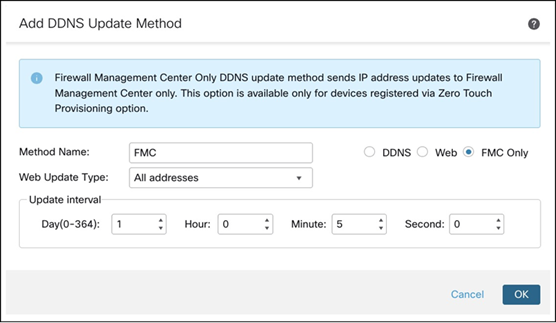
Step 8. Click OK. You will see the method that you created in the DDNS Update Methods table.
Step 9. Click the DDNS Interface Settings tab.
Step 10. Click +Add to add dynamic DNS configuration.
Step 11. In the Add Dynamic DNS Configuration dialog box, configure these parameters:
i. From the Interface drop-down list, choose the interface enabled for manager access. In this example, the interface is outside1.
ii. From the Method Name drop-down list, choose the method that you created.
iii. From the Host Name drop-down list, choose a variable for the host name or click + to create a host name variable. In this example, the variable is $hostname.
iv. Click OK.
Step 12. Click Save.
Configure Template Settings and Map Template to a Device Model
Step 1. Choose Devices > Template Management.
Step 2. Click the Edit icon of the template in which you want to add the physical interface.
Step 3. Click Template Settings.
Step 4. In the left pane, click General to add licenses.
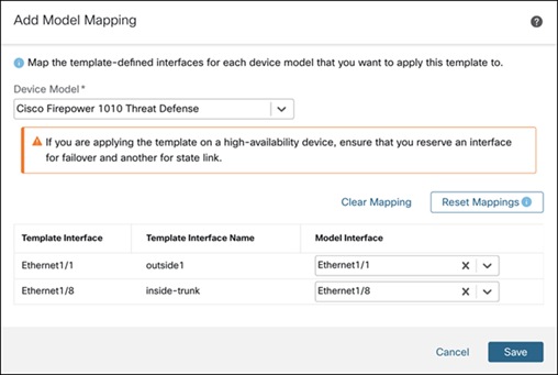
Step 5. In the left pane, click Model Mapping to map the template to a device model.
Step 6. Click Add Model Mapping.
Step 7. In the Add Model Mapping dialog box, configure these parameters:
i. From the Device Model drop-down list, choose the model. In this example, the model is Cisco Firepower 1010 Threat Defense device.
ii. From the Model Interface drop-down list, choose the data interface and the inside interface.
iii. Click Save.
Onboard Threat Defense Devices Using ZTP
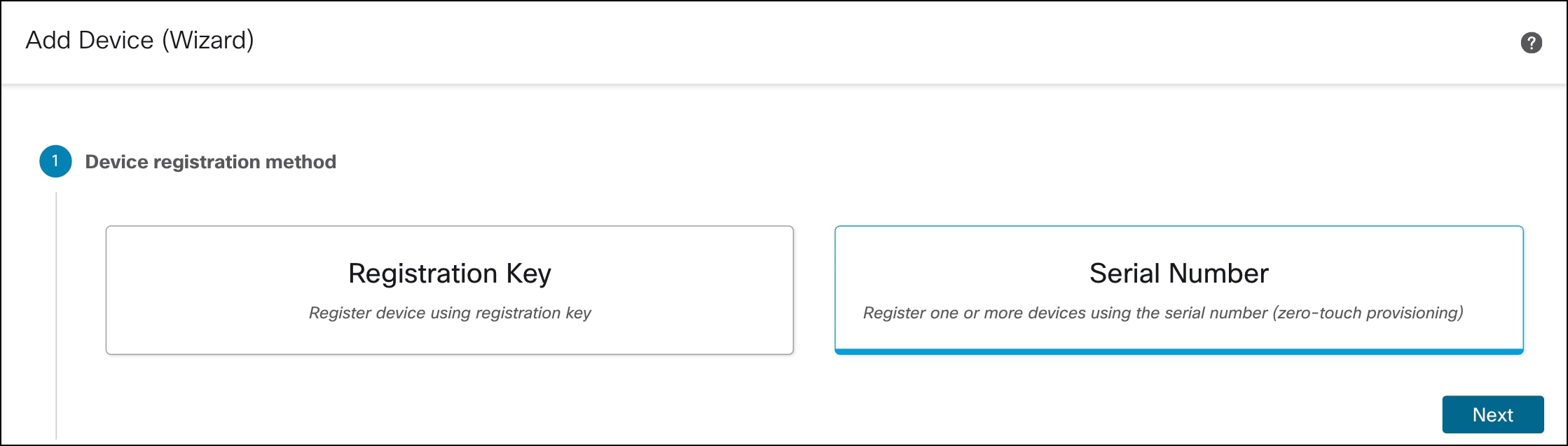
Step 1. Choose Devices > Device Management.
Step 2. Click Add > Device (Wizard).
Step 3. In the Device registration method, click Serial Number and click Next.
Step 4. In Initial device configuration, configure these parameters:
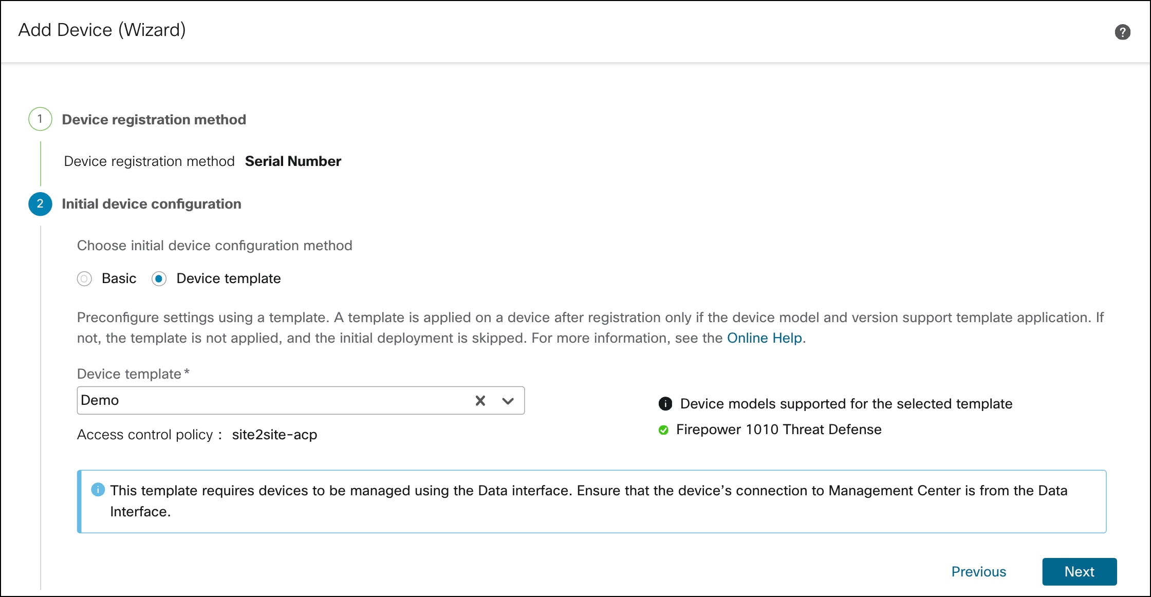
i. Click the Device template radio button.
ii. From the Device template drop-down list, choose a device template for the device, and click Next.
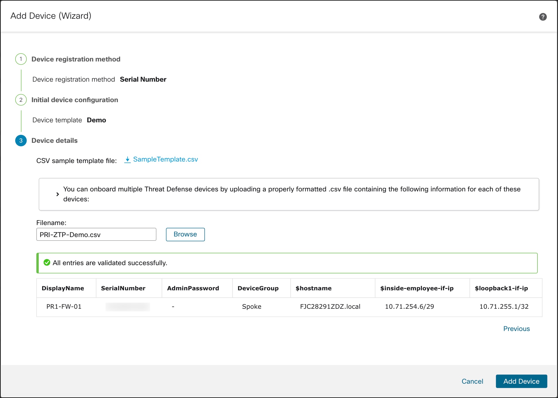
Step 5. In Device details:
i. Download the SampleTemplate.csv. Use this format when uploading your CSV file to Management Center.
ii. Define the required parameters for each device, such as Display Name, Serial Number, Admin Password, and any additional variables.
iii. Drag and drop your CSV template file or click Browse to select the CSV template file that you want to upload. A validation check is done on the file after you upload it.
iv. After the CSV template file has been uploaded successfully, the content of the CSV template file is displayed in a table format.
Step 6. Click Add Device to initiate device registration.
The template configurations are applied after the device is successfully registered with the Management Center.
In the Notifications > Tasks window, you can view the messages related to the device registration, device discovery, and device template application.
A Device Template Apply report is generated after the apply template task is completed. This report is generated on both successful and unsuccessful application of the template on the device. You will see a link to this report in the Notifications > Tasks window.
Step 7. Choose Devices > Device Management to see the onboarded device, PRI-FW-01.
Onboard Threat Defense Device to Management Center Using Registration Key
You can register an individual device by specifying the registration key and defining variables in the Management Center. This method is used to onboard a single Threat Defense device, with or without a device template.
Note: In this example, we onboard the device without a template.
Network Topology
In this example, we onboard a single virtual Secure Firewall device named MCT-FW-01 using the registration key method.
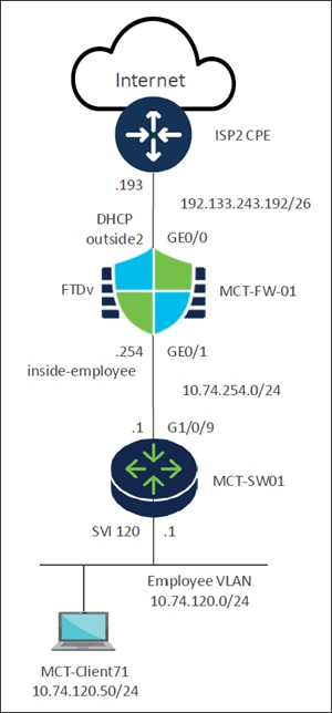
This network topology diagram illustrates a typical setup for a small to medium-sized enterprise, connecting internal users to the Internet through a firewall and a switch.
● Internet: Represents the external network or the public internet.
● ISP2 CPE:
◦ Upstream device connecting to an Internet Service Provider (ISP).
◦ It connects the internal network to the Internet.
● FTDv (MCT-FW-01) - Cisco Firewall Threat Defense Virtual device:
◦ This device acts as a firewall, providing security and network segmentation.
◦ GE0/0 Interface (Outside): Connects to the ISP2 CPE. It's configured to receive an IP address through DHCP (DHCP outside2) from the subnet 192.133.243.192/26. The .193 is on the ISP side.
◦ GE0/1 Interface (Inside - inside-employee): Connects to the internal network through the switch. This interface has an IP address ending in .254 within the 10.74.254.0/24 subnet. This subnet likely serves as the transit network between the firewall and the internal switch.
● MCT-SW01 - Switch:
◦ This is a network switch, likely a Layer 3 device given the presence of an SVI (Switched Virtual Interface).
◦ G1/0/9 Interface: Connects to the FTDv (MCT-FW-01). The IP address on this interface (or the connected SVI) is .1 within the 10.74.254.0/24 subnet, making it the default gateway for the 10.74.254.0/24 network segment.
◦ SVI 120: This is a Switched Virtual Interface for VLAN 120. It serves as the default gateway for the Employee VLAN. The IP address for SVI 120 is .1 within the 10.74.120.0/24 subnet.
● MCT-Client71 - Employee Client:
◦ This represents an end-user device (for example, a laptop).
◦ It is part of the Employee VLAN (VLAN 120), which uses the 10.74.120.0/24 network.
◦ Its specific IP address is 10.74.120.50/24.
Workflow
Onboarding using a registration key involves a two-step process:
1. In the Threat Defense CLI, complete the initial configuration:
a. Add the Management Center details to the device.
i. Configure the hostname or IP address of the Management Center.
ii. Specify a registration key (up to 36 alphanumeric characters).
iii. (Optional) Provide a unique NAT ID (up to 36 alphanumeric characters) if either the Management Center or the device is located behind a NAT device.
iv. (Optional) Specify a display name for the Management Center.
b. Ensure the management data interface on the device is configured to establish connectivity with the Management Center. This interface can be inbound or outbound.
2. In the Management Center application:
a. Add the device with or without templates and provide the device hostname or IP address which is optional.
b. Enter a display name for the device.
c. Input the registration key configured on the device in the previous step.
d. (Optional) Specify the unique NAT ID.
e. Select an Access Control policy.
f. (Optional) Assign licenses.
Connect Threat Defense Device to Management Center
Step 1. Connect to the Threat Defense CLI, using SSH to the Management interface.
Step 2. Log in using the username and password. The default username is admin and the password is Admin123.
firepower login: admin
Password:
Last login: Thu Feb 6 15:09
Step 3. The first time you log in to the Threat Defense, you are prompted to accept the End User License Agreement (EULA) and, if using an SSH connection, to change the admin password. You are then presented with the CLI setup script.
Step 4. Verify that the device has no Management Center configured to manage it.
> show managers
No managers configured.
Step 5. Add the Management Center that will manage this threat defense.
configure manager add {hostname | IPv4_address | DONTRESOLVE} reg_key [nat_id] [display_name]
In this example, we specify the following information:
- IPv4_address of the Management Center: 192.33.243.243
- reg_key: cisco. The registration key is a one-time-use shared secret. The key can be up to 37-characters in length and include alphanumerical characters (A–Z, a–z, 0–9) and the hyphen (-). The registration key does not need to be unique per device.
- nat_id: mct (In this example, the Management Center is behind a NAT device, and hence we need to enter a unique NAT ID.
- display_name: FMC
> configure manager add 192.33.243.243 cisco mct FMC
Manager FMC successfully configured.
Please make note of reg_key as this will be required while adding Device in FMC.
Step 6. Configure a data interface for manager access.
In this example, GigabitEthernet0/0 is the data interface designated for management traffic, while outside2 is the name of the data interface.
> configure network management-data-interface
Data interface to use for management: GigabitEthernet0/0
Specify a name for the interface [outside]: outside2
IP address (manual / dhcp) [dhcp]:
Comma-separated list of DNS servers [200.67.222.222,208.67.220.220]:
DDNS server update URL [none]:
The data interface has been configured to handle management traffic.
Step 7. To verify the details of the manager configured on the device, execute the following command:
> show managers
Type: Manager
Host: 192.133.243.243
Display name: FMC
Identifier: mct
Registration: Pending
You will see that the device is configured to be managed by a Management Center with the IP address 192.133.243.243.
Step 8. To verify the interface details, execute the following command:
> show interface ip brief
Interface IP-Address OK? Method Status Prot
GigabitEthernet0/0 192.133.243.221 YES DHCP up up
You will see that the data interface GigabitEthernet0/0 has obtained a DHCP IP address. In this example, the data interface IP address is 192.133.243.221.
Register your Device to Firewall Management Center
Step 1. Choose Devices > Device Management.
Step 2. From the Add drop-down menu, choose Device.
Step 3. Click Registration Key, and then click Next.
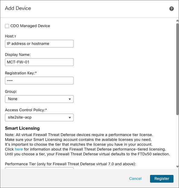
Step 4. In the Add Device dialog box, configure the following parameters:
i. In the Host field, enter the IP address or the hostname of the device you are adding. In this example, we leave this field blank because the device is behind NAT.
ii. In the Display Name field, enter a name for the device as you want it to display in the Firewall Management Center. You cannot change this name later. In this example, the display name is MCT-FW-01.
iii. In the Registration Key field, enter the same registration key from your initial configuration. In this example, the registration key is cisco. We specified this key to complete the Threat Defense initial configuration using the CLI in the previous section.
iv. From the Access Control Policy drop-down list, choose an access control policy. In this example, we choose the site2site-acp policy.
v. In the Unique NAT ID field, enter the same ID from your initial configuration. In this example, the NAT ID is mct. We specified this ID as identified to complete the Threat Defense initial configuration using the CLI in the previous section.
Step 5. Click Register.
The device registration will be initiated.
In the Notifications > Tasks window, you can view the messages related to the device registration and device discovery.
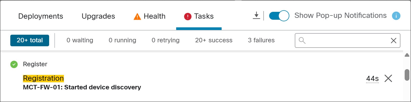
It takes a few minutes to complete the deployment.
Step 6. Click the Deployments tab to see the success message for the device deployment.
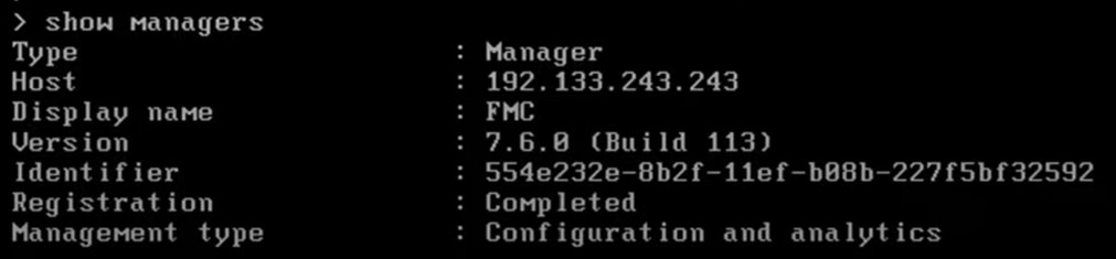
Step 7. To confirm that the device registration is complete, execute the following command on the device’s CLI.
> show managers
In this example, the output below indicates that the device is configured to the Management Center.
◦ Choose Device > Device Management to see the onboarded MCT-FW-01 device.
◦ Click the device to view the configured data management interface.
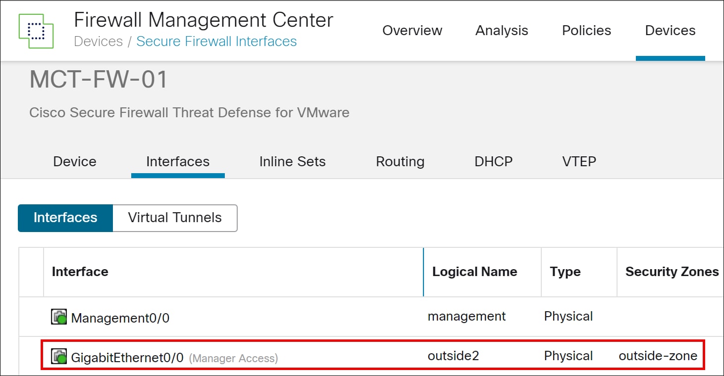
Add an Interface
In this example, we configure the GigabitEthernet0/1 interface designated for an internal protected network.
Step 1. Choose Devices > Device Management.
Step 2. Click the device you want to configure.
In this example, we will configure the interface of MCT-FW-01.
Step 3. Click the Edit icon to edit the device settings.
Step 4. In the Edit Physical Interface dialog box, configure the following parameters:
i. In the Name field, enter the interface name. In this example, the interface name is inside-employee.
ii. Check the Enable check box.
iii. From the Security Zone drop-down list, choose a zone. In this example, we choose inside-zone.
iv. Click the IPv4 tab. The IP Type must be Use Static IP.
v. In the IP Address field, enter a static IP address. In this example, the IP address is 10.74.254.254/24.
vi. Click OK.
vii. Click Save.
Configure a Loopback Interface
A loopback interface is a software-only interface that emulates a physical interface. This interface is reachable on IPv4 and IPv6 through multiple physical interfaces. The loopback interface helps to overcome path failures; it is accessible from any physical interface, so if one goes down, you can access the loopback interface from another. The use of the loopback interface is explained later in this guide.
Step 1. From the Add Interfaces drop-down list, choose Loopback Interface.
Step 2. In the General tab, configure the following parameters:
i. Name—Enter a name for the loopback interface. In this example, the interface name is loopback1.
ii. Enabled—Check the check box to enable the loopback interface.
iii. Loopback ID—Enter the loopback ID between 1 to 1024. In this example, the ID is 1.
Step 3. Click the IPv4 tab and specify the IP Address.
In this example, the IP address is 10.74.255.1.32.
Step 4. Click OK.
Step 5. Click Save.
Step 6. In the Management Center menu bar, click Deploy.
In this example, check MCT-FW-01 device and then click Deploy.
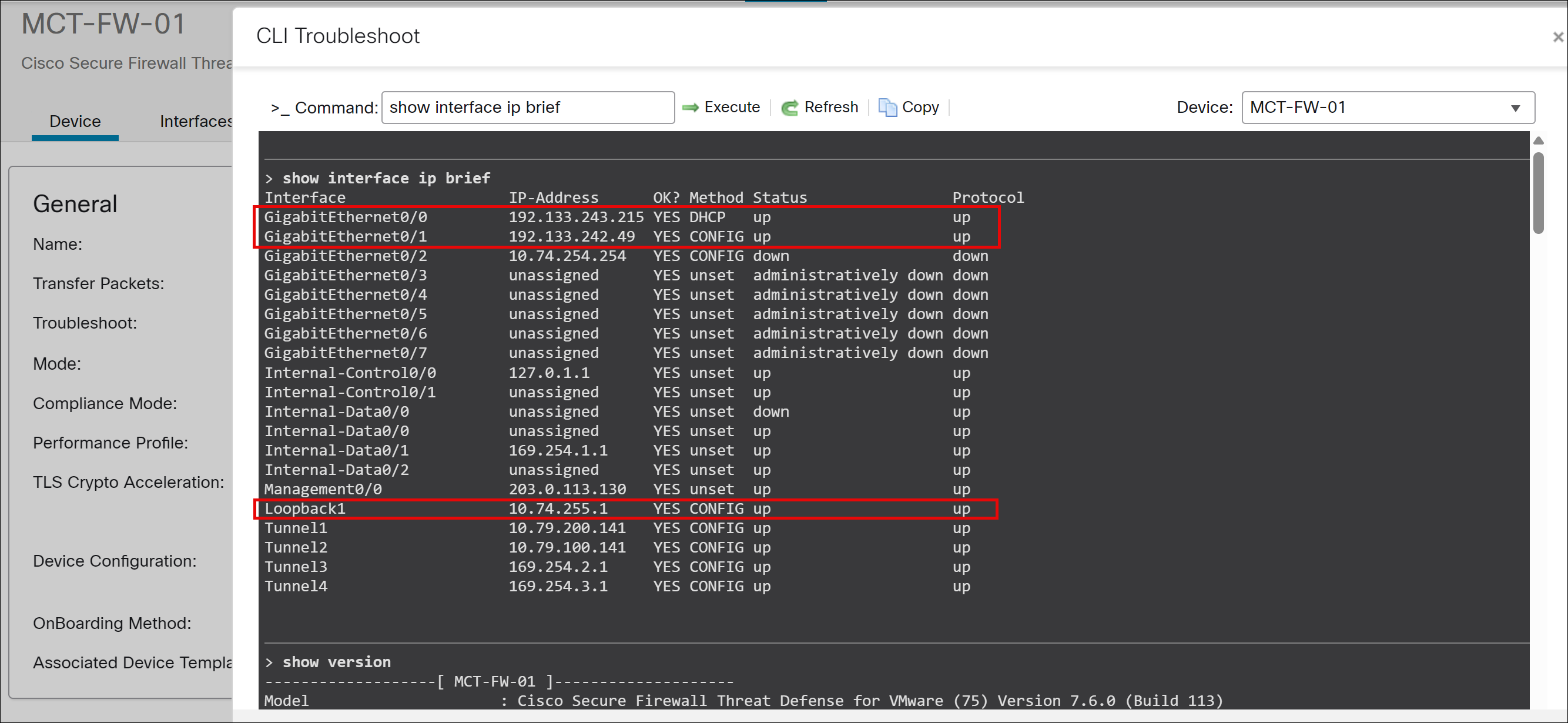
Verify Interface Connectivity Using CLI
After onboarding a network device with a registration key, it is essential to confirm that all relevant interfaces (such as outside, inside, and loopback) have successfully obtained their configured IP addresses and are reachable.
Step 1. Choose Devices > Device Management.
Step 2. Click the device you onboarded using the registration key.
In this example, the device is MCT-FW-01.
Step 3. Click the Device tab.
Step 4. In the General area, click CLI.
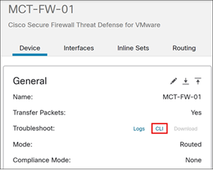
In this example, GigabitEthernet0/0 (outside), GigabitEthernet0/1 (inside), and Loopback1 interfaces are operational and have successfully obtained the configured IP addresses.
Step 5. Test reachability to the inside network:
> ping 10.74.254.1
Sending 5, 100-byte ICMP Echos to 10.74.254.1, timeout is 2 seconds:
!!!!!
Success rate is 100 percent (5/5), round-trip min/avg/max = 1/1/1 ms
Step 6. Test reachability to the outside network:
> ping 8.8.8.8
Sending 5, 100-byte ICMP Echos to 8.8.8.8, timeout is 2 seconds:
!!!!!
Success rate is 100 percent (5/5), round-trip min/avg/max = 10/10/10 ms
Step 7. Test reachability to the loopback interface:
> ping 10.74.255.1
Sending 5, 100-byte ICMP Echos to 10.74.255.1, timeout is 2 seconds:
!!!!!
Success rate is 100 percent (5/5), round-trip min/avg/max = 1/1/1 ms
For more details on SD-WAN design and additional use cases, see Cisco Secure Firewall Threat Defense SD-WAN Design and Deployment Guide.