Route Application Traffic to the Internet Using DIA in Cisco Secure Firewall Management Center
Available Languages
Bias-Free Language
The documentation set for this product strives to use bias-free language. For the purposes of this documentation set, bias-free is defined as language that does not imply discrimination based on age, disability, gender, racial identity, ethnic identity, sexual orientation, socioeconomic status, and intersectionality. Exceptions may be present in the documentation due to language that is hardcoded in the user interfaces of the product software, language used based on RFP documentation, or language that is used by a referenced third-party product. Learn more about how Cisco is using Inclusive Language.
- US/Canada 800-553-2447
- Worldwide Support Phone Numbers
- All Tools
 Feedback
 Feedback
Route Application Traffic from the Branch to the Internet Using Direct Internet Access
Traditional network deployments typically route all internet traffic through a central site using a perimeter firewall and encrypted VPN tunnels, which can cause increased latency, packet loss, higher costs, and complex management.
Direct Internet Access (DIA), a key SD-WAN feature in Cisco Secure Firewall, addresses these challenges by routing branch office application traffic directly to the internet, bypassing the central site. DIA uses Policy-Based Routing (PBR) to identify and forward traffic based on attributes such as network, port, user groups, applications, and security group tags (SGTs), reducing latency and improving user experience. This approach simplifies network management, lowers bandwidth consumption, and enhances performance by enabling local internet exit points at branch firewalls.
The different ways of steering traffic using PBR are:
● Source IP address-based routing (Version 7.1 and later)
● Application-aware routing (Version 7.1 and later)
● Application-aware routing with path monitoring
◦ IP-based (Version 7.2 and later)
◦ HTTP-based (Version 7.4 and later)
● Identity-based routing (AD user, user group and SGT) (Version 7.4 and later)
Benefits of Using Direct Internet Access
● Improve internet speeds and branch office user experience by reducing latency, packet loss, and jitter.
● Reduce bandwidth usage at the central site.
● Enable intelligent application routing with dynamic path selection based on real-time performance metrics, eliminating the need for manual intervention.
● Steer application traffic based on the link health and network state.
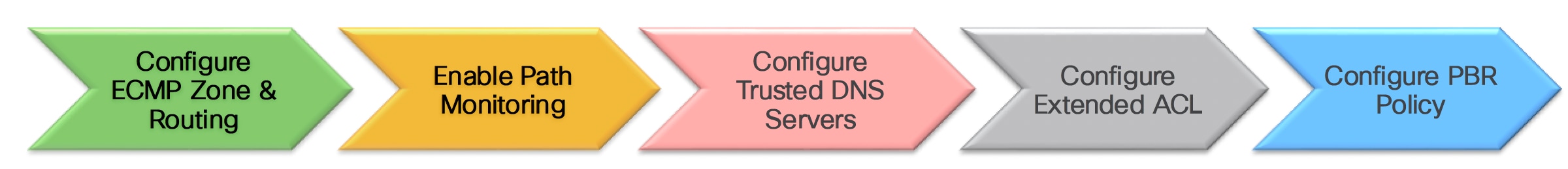
Workflow for Configuring Direct Internet Access
Configure Direct Internet Access
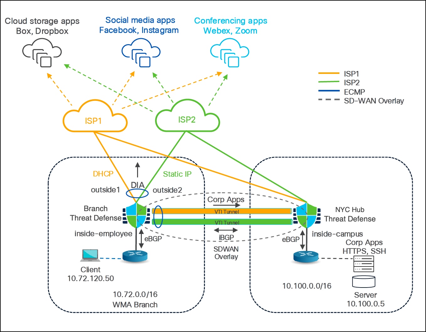
In this example, we use the Worchester, MA (WMA) SD-WAN branch with Firepower 1120 (WMA-FW-01) for PBR routing. It has two WAN interfaces:
● outside1 for ISP1
● outside2 for ISP2
The interface connected to the LAN is inside-employee.
For ease of understanding, we use only the New York City, NY (NYC) hub device in this example.
Create an ECMP Zone
We create an ECMP zone to load balance traffic amongst egress interfaces.
Step 1. Choose Devices > Device Management.
Step 2. Click the Edit icon adjacent to the device (WMA-FW-01).
Step 3. Click the Routing tab.
Step 4. Click ECMP.
Step 5. Click Add.
Step 6. In the Add ECMP dialog box, enter a name for the ECMP zone.
In this example, the ECMP zone is ECMP-WAN.
Step 7. Select interfaces under the Available Interfaces list for the ECMP zone and click Add.
In this example, the selected egress interfaces are outside1 and outside2.
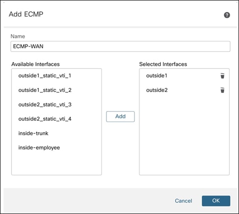
Step 8. Click OK.
The ECMP page displays the newly created ECMP zone.
Step 9. Click Save.
Repeat Step 1 to 9 to create another ECMP zone (ECMP-VTI) with the four static VTIs of the device. This ECMP zone will load share the traffic between these VTIs. The four static VTIs of the device that you must choose are:
● outside1_static_vti_1 (SVTI to NYC hub using outside1 interface)
● outside1_static_vti_2 (SVTI to NNJ hub using outside1 interface)
● outside2_static_vti_3 (SVTI to NNJ hub using outside2 interface)
● outside2_static_vti_4 (SVTI to NYC hub using outside2 interface)
Configure Path Monitoring on an Interface
Step 1. Choose Devices > Device Management.
Step 2. Click the Edit icon adjacent to the device (WMA-FW-01).
Step 3. Click the Interfaces tab.
Step 4. Click the Edit icon adjacent to the interface (outside1).
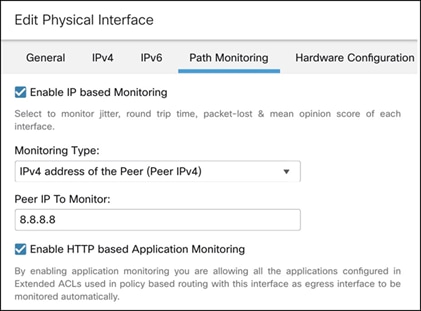
Step 5. Click the Path Monitoring tab.
Step 6. Check the Enable IP based Path Monitoring check box.
Step 7. From the Monitoring Type drop-down list, choose the relevant option.
In this example, we choose the IPv4 address of the Peer (Peer IPv4) option.
Note: Ensure that you can reach the peer so that the device can collect the metrics for PBR.
Step 8. In the Peer IP To Monitor field, enter the IP address of the peer device.
In this example, the IP address is 8.8.8.8.
Step 9. Click OK.
Repeat Step 1 to 9 to configure path monitoring on outside2 interface of the device.
Create a DNS Server Group Object
You must create one or more DNS server groups before you configure trusted DNS servers. DNS server groups are defined within trusted DNS servers to allow Threat Defense devices to trust the DNS response from these authorized servers.
Prerequisites
● Ensure you have interfaces that connect to the DNS servers.
● Ensure that the managed device has appropriate static or dynamic routes to access the DNS servers.
Step 1. Choose Objects > Object Management.
Step 2. In the left pane, click Network.
Step 3. Click Add Network and choose Add Object from the drop-down list.
Step 4. In the Name field, enter a name for the DNS server object.
In this example, we create two DNS server objects: Ciscovalidated-dns-primary and Ciscovalidated-dns-secondary.
Step 5. Select the Host radio button and enter the IP address of the DNS server.
In this example, the IP addresses of the DNS servers are:
- Ciscovalidated-dns-primary: 10.100.0.5
- Ciscovalidated-dns-secondary: 10.200.0.5
-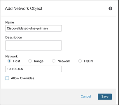
Step 6. Click Save.
Configure a Trusted DNS Server
You must define the configured DNS server groups as trusted DNS servers to allow the Threat Defense device to snoop DNS responses from authorized DNS servers.
Step 1. Choose Devices > Platform Settings.
Step 2. Create or edit a Threat Defense policy.
Step 3. In this example, the Threat Defense policy is Threat-defense-setting-policy assigned to the WMA-FW-01 device.
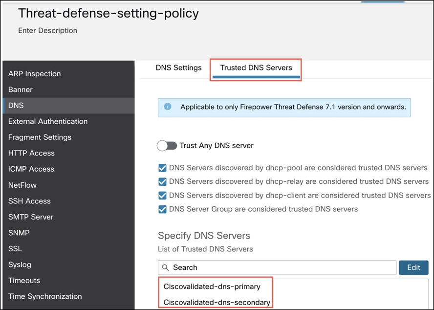
Step 4. In the left pane, click DNS.
Step 5. Click the Trusted DNS Servers tab.
Step 6. Click Edit under Specify DNS Servers.
Step 7. In the Select DNS Servers dialog box, select the required host object and click Add to include it to Selected DNS Servers list.
In this example, we select the two DNS server objects: Ciscovalidated-dns-primary and Ciscovalidated-dns-secondary.
Step 8. Click Save. The DNS servers are displayed in the Trusted DNS Servers page.
Configure an Extended ACL Object
You must configure extended ACLs for Threat Defense device to direct the application traffic to the Internet through different egress interfaces using PBR.
Step 1. Choose Objects > Object Management.
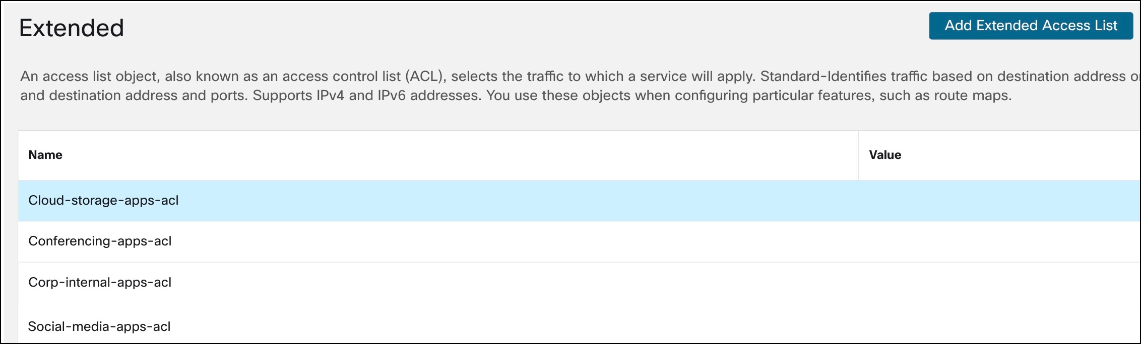
Step 2. In the left pane, click Access Lists > Extended.
Step 3. Click Add Extended Access List.
Step 4. In the New Extended ACL Object dialog box, configure these parameters:
i. In the Name field, enter a name for the object.
ii. Click Add to create a new extended access list.
iii. Configure the parameters in the Add Extended Access List Entry dialog box.
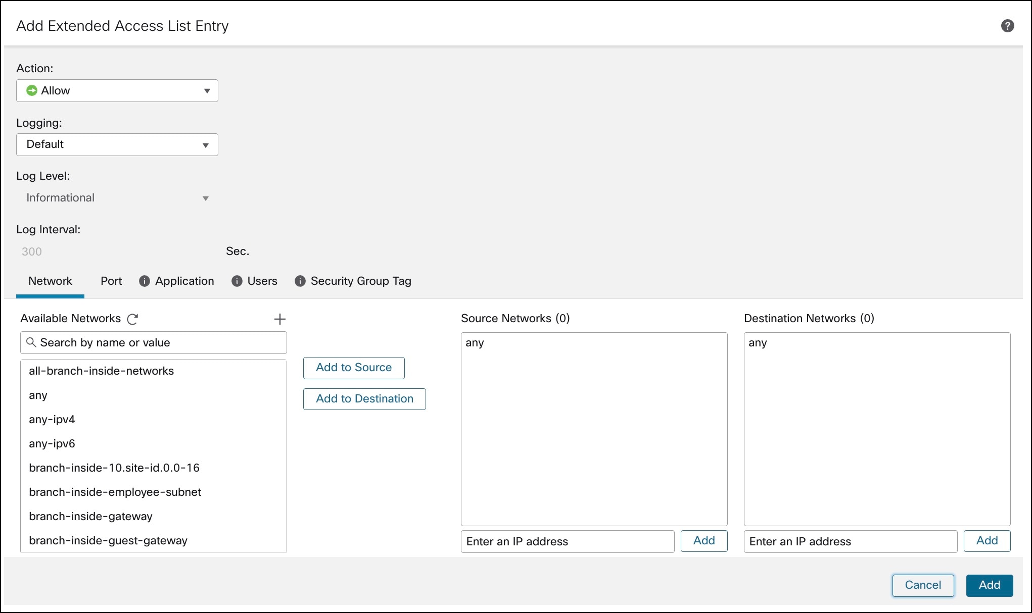
iv. From the Action drop-down list, choose Allow.
v. Click the Network, Port, Application, Users, or Security Group Tag tab and choose the required access control properties.
vi. Click Add.
Step 5. Click Save. The extended ACLs are displayed in the Extended ACL page.
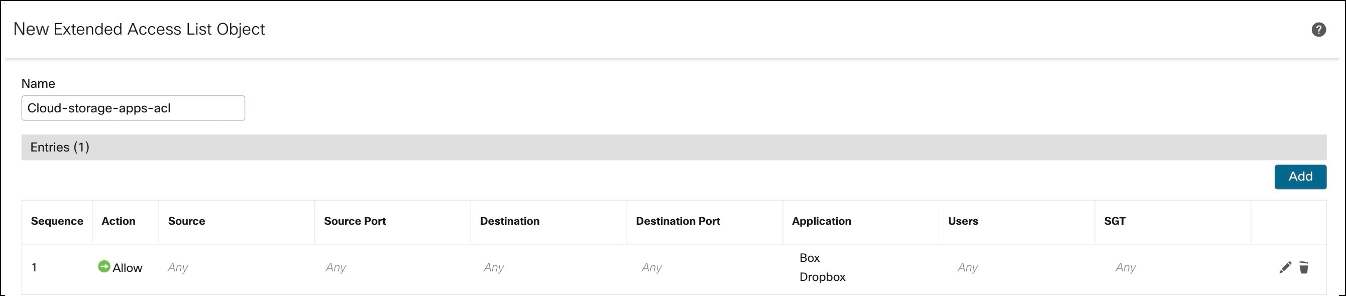
Example 1:
Create an extended ACL for cloud storage applications such as Box and Dropbox:
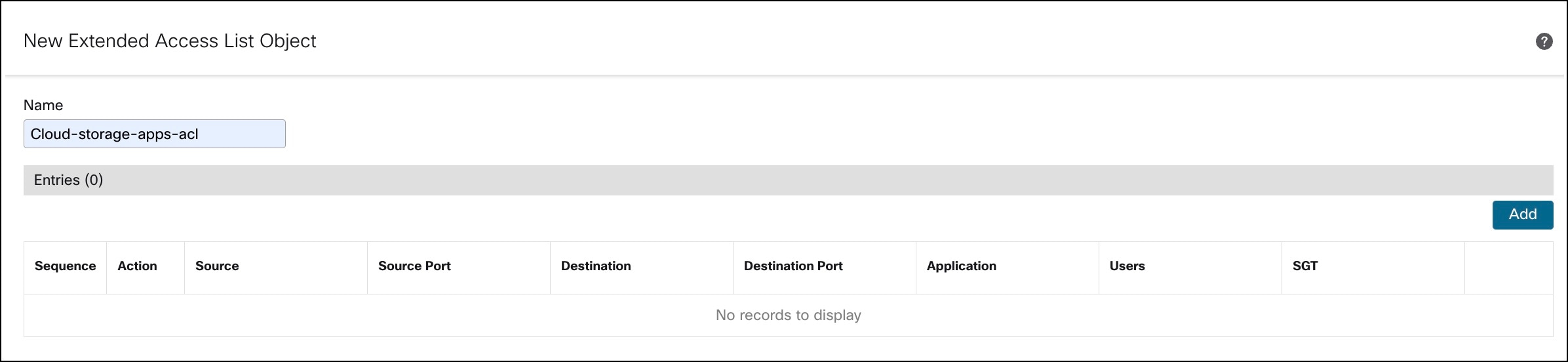
In the New Extended ACL Object dialog box, configure these parameters:
a. In the Name field, enter a name (Cloud-storage-apps-acl) for the object.
b. Click Add to create a new extended access list.
c. Configure the parameters in the Add Extended Access List Entry dialog box.
d. From the Action drop-down list, choose Allow.
e. Click the Network tab.
f. By default, the Source Network and Destination Network is any.
g. Click the Application tab. Search for Box and Dropbox in the Available Applications list.
h. Select Box and Dropbox and click Add to Rule.
i. Click Save.
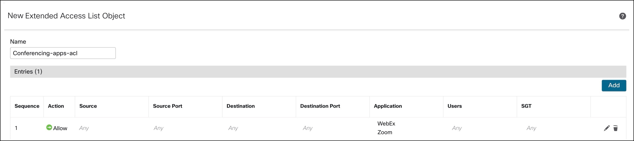
Example 2:
Repeat the steps in example 1 and create an extended ACL (Conferencing-apps-acl) for conferencing applications such as Webex and Zoom.
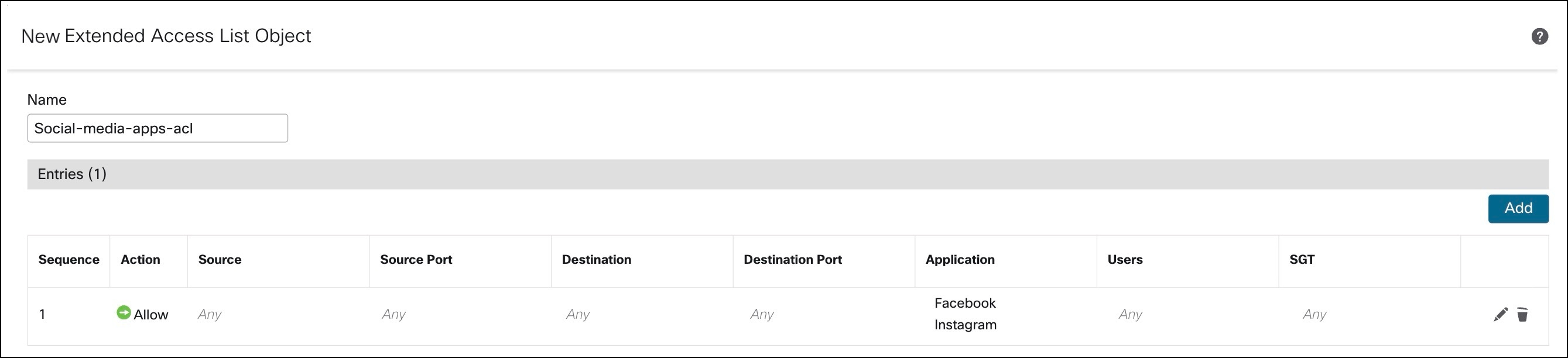
Example 3:
Repeat the steps in example 1 and create an extended ACL (Social-media-apps-acl) for social media applications such as Facebook and Instagram.
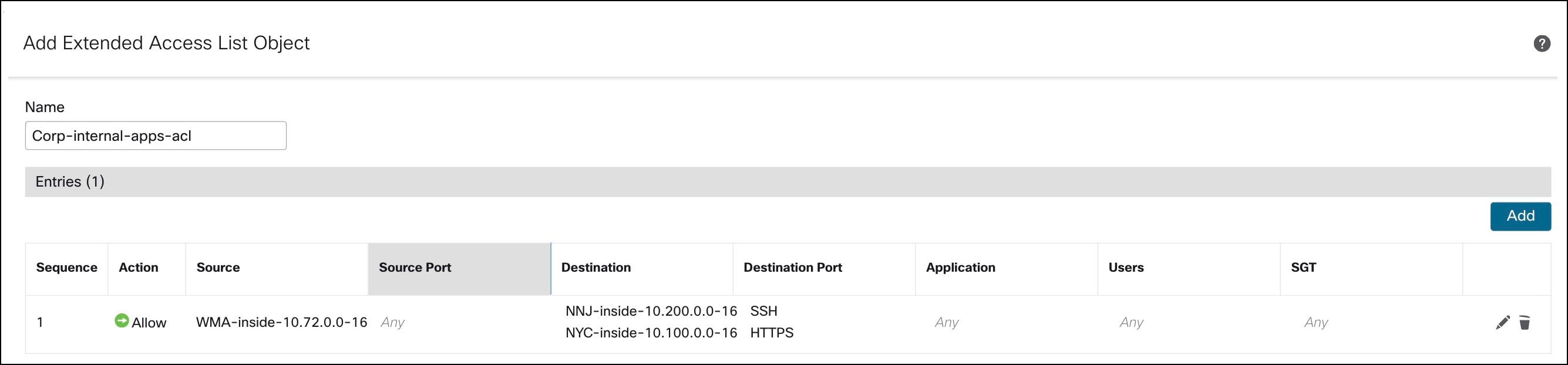
Example 4:
Create an extended ACL (Corp-internal-apps-acl) for accessing applications within the branch LAN.
In the New Extended ACL Object dialog box, configure these parameters:
a. In the Name field, enter a name (Corp-internal-apps-acl) for the object.
b. Click Add to create a new extended access list.
c. Configure the parameters in the Add Extended Access List Entry dialog box.
d. From the Action drop-down list, choose Allow.
e. Click the Network tab.
f. For the Source Network, you must add the inside network object of the WMA branch.
g. Click + adjacent to Available Networks to create this network object, if required. In this example, it is WMA-inside-10.72.0.0-16 with IP address as 10.72.0.0/16.
h. In Available Networks, search for WMA-inside-10.72.0.0-16.
i. Click Add to Source.
j. For the Destination networks, add the inside network objects for the NYC and NNJ hubs.
k. Click + adjacent to Available Networks to create this network object, if required. In this example, it is NNJ-inside-10.200.0.0-16 with IP address as 10.200.0.0/16, and NYC-inside-10.100.0.0-16 with IP address as 10.100.0.0/16.
l. In Available Networks, search for NNJ-inside-10.200.0.0-16 and NYC-inside-10.100.0.0-16.
m. Click Add to Destination.
n. Click the Port tab.
o. Search for SSH and HTTPS in the Available Ports list.
p. Click Add to Destination.
q. Search for SSH and HTTPS in the Available Applications list, and click Add to Rule.
r. Click Save.
Configure Interface Priority
Step 1. Choose Devices > Device Management.
Step 2. Click the Edit icon adjacent to the device (WMA-FW-01).
Step 3. Click the Routing tab.
Step 4. In the left pane, click Policy Based Routing.
Step 5. Click Configure Interface Priority.
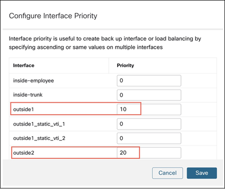
Step 6. In the Configure Interface Priority dialog box, provide the priority number against the interfaces.
Traffic is routed to the interface with the least priority value first. When an interface is not available, traffic is forwarded to the interface with the next lowest priority value. When the priority value is the same for all the interfaces, the traffic is balanced among the interfaces.
In this example, the priority for outside1 interface is 10 and priority for outside2 interface is 20.
Step 7. Click Save.
Configure a Policy Based Routing Policy
Step 1. Choose Devices > Device Management.
Step 2. Click the Edit icon adjacent to the device (WMA-FW-01).
Step 3. Click the Routing tab.
Step 4. In the left pane, click Policy Based Routing.
Step 5. Click Add.
Step 6. In the Add Policy Based Route dialog box, from the Ingress Interface drop-down list, choose an interface.
Note: Only interfaces that have logical names and that belong to a global virtual router are listed in the drop-down.
In this example, the ingress interface is inside-employee.
Step 7. Click Add to specify a match criteria and a forward action in the policy.
Step 8. In the Add Forwarding Actions dialog box, configure these parameters:
i. From the Match ACL drop-down, choose an extended ACL.
ii. From the Send To drop-down list, choose Egress Interfaces.
iii. From the Interface Ordering drop-down list, choose one of these options: Interface Priority, Order, Minimal Jitter, Maximum Mean Opinion Score, Minimal Round Trip Time, or Minimal Packet Loss. See the examples below.
iv. In the Available Interfaces box, click + adjacent to an interface to add the selected egress interface.
v. Click Save.
Step 9. Deploy the PBR policy on the device.
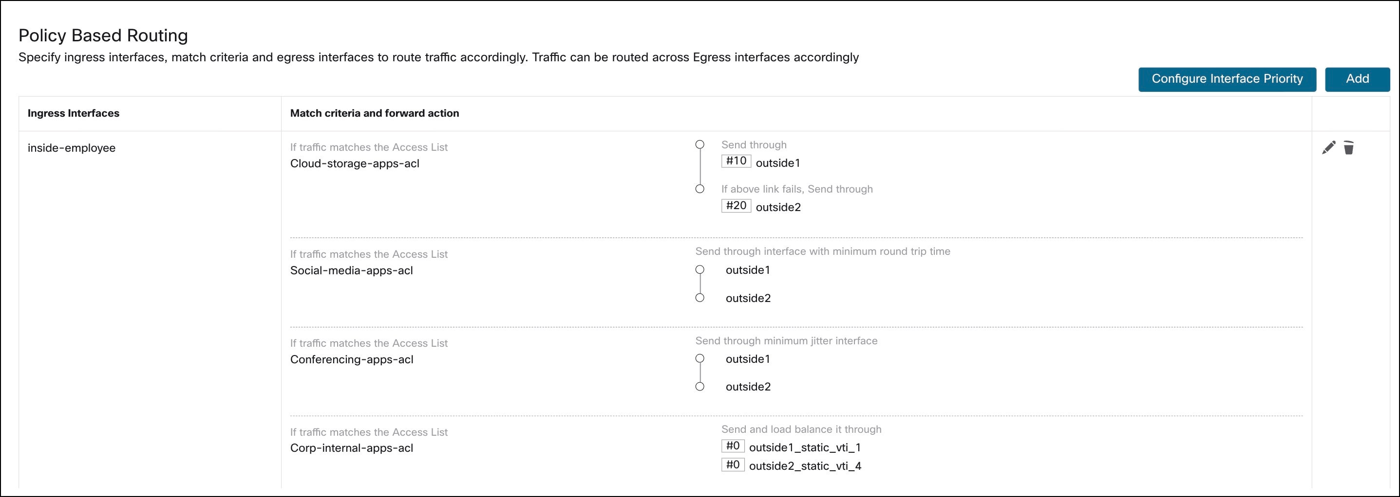
Example 1:
Configure the PBR policy to forward cloud storage application traffic through a lower-priority egress interface.
Step 1. In the Add Policy Based Route dialog box, from the Ingress Interface drop-down list, choose inside-employee.
Step 2. Click Add.
Step 3. In the Add Forwarding Actions dialog box, configure these parameters:
i. From the Match ACL drop-down list, choose Cloud-storage-apps-acl.
ii. From the Send To drop-down list, choose Egress Interfaces.
iii. From the Interface Ordering drop-down list, choose Interface Priority.
iv. In the Available Interfaces box, click + adjacent to outside1 and outside2.
v. Click Save.
Example 2:
Configure the PBR policy to forward social media application traffic through an egress interface with minimal RTT.
Step 1. In the Add Policy Based Route dialog box, from the Ingress Interface drop-down list, choose inside-employee.
Step 2. Click Add.
Step 3. In the Add Forwarding Actions dialog box, configure these parameters:
i. From the Match ACL drop-down list, choose Social-media-apps-acl.
ii. From the Send To drop-down list, choose Egress Interfaces.
iii. From the Interface Ordering drop-down list, choose Minimal Round Trip Time.
iv. In the Available Interfaces box, click + adjacent to outside1 and outside2.
v. Click Save.
Example 3:
Configure the PBR policy to forward conferencing application traffic through an egress interface with minimal jitter.
Step 1. In the Add Policy Based Route dialog box, from the Ingress Interface drop-down list, choose inside-employee.
Step 2. Click Add.
Step 3. In the Add Forwarding Actions dialog box, configure these parameters:
i. From the Match ACL drop-down list, choose Conferencing-apps-acl.
ii. From the Send To drop-down list, choose Egress Interfaces.
iii. From the Interface Ordering drop-down list, choose Minimal Jitter.
iv. In the Available Interfaces box, click + adjacent to outside1 and outside2.
v. Click Save.
Example 4:
Configure the PBR policy to forward corporate application traffic using ECMP across multiple egress VTI tunnel interfaces.
Step 1. In the Add Policy Based Route dialog box, from the Ingress Interface drop-down list, choose inside-employee.
Step 2. Click Add.
Step 3. In the Add Forwarding Actions dialog box, configure these parameters:
i. From the Match ACL drop-down list, choose Corp-internal-apps-acl.
ii. From the Send To drop-down list, choose Egress Interfaces.
iii. From the Interface Ordering drop-down list, choose Interface Priority.
iv. In the Available Interfaces box, click + adjacent to outside1_static_vti_1 and outside2_static_vti_4. These are the VTIs terminating at the New York City, NY (NYC) hub device.
v. Click Save.
Verify Configurations
You can verify the configurations using the Management Center or the device CLI.
To view the device configurations using the Management Center:
Step 1. Choose Devices > Device Management.
Step 2. Click the Device tab.
Step 3. Click CLI in the General card.
Step 4. In the CLI Troubleshoot dialog box, enter the commands shown below in the Command field and click Execute.
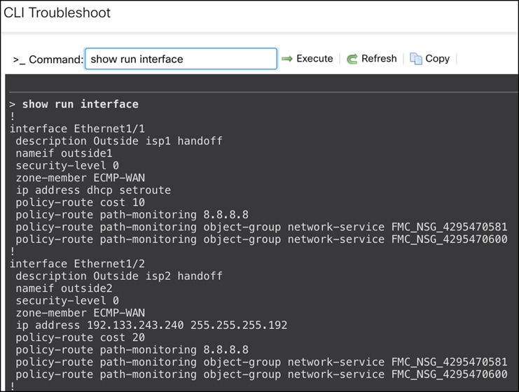
Verify Interface Configurations
Run the show run interface command to see the interface configurations of the device.
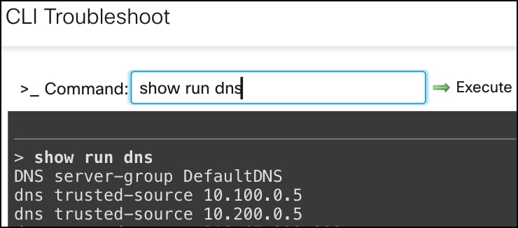
Verify DNS Configurations
Run the show run interface command to see the interface configurations of the device.
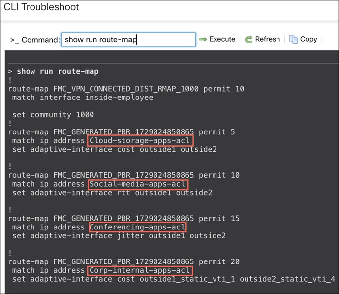
Verify Route Map Configurations
Run the show run route-map command to see the route maps of the device.
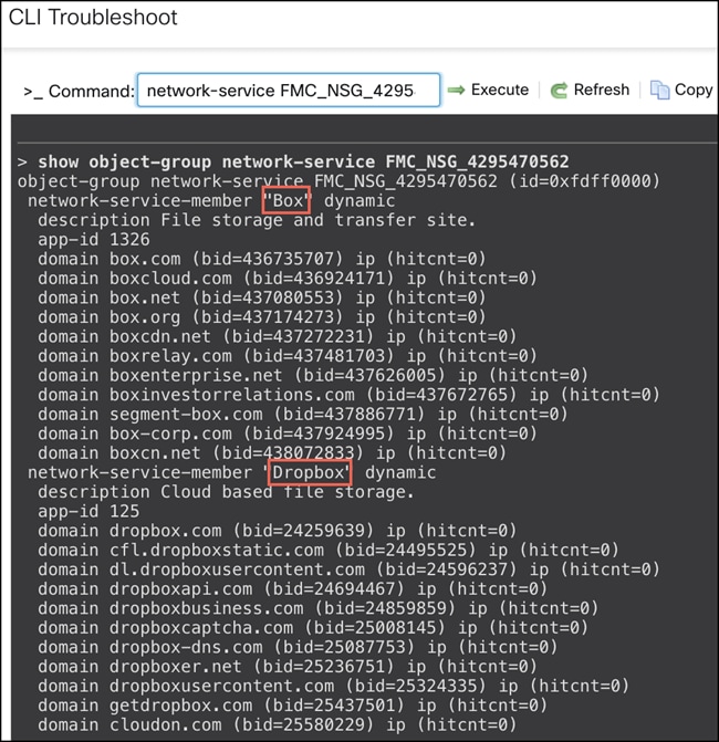
Verify Access Lists and Network Service Groups Configurations
Run the show run access list <access list_name> command to see the details of an access list.
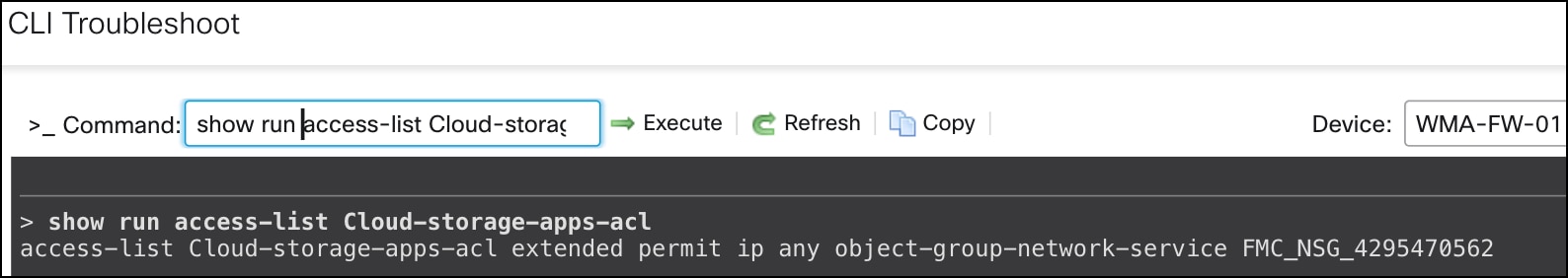
Run the show object-group network-service <network-service-groups-name> command to see the NSG configurations. <network-service-groups-name> is derived from the above show command for an access list.
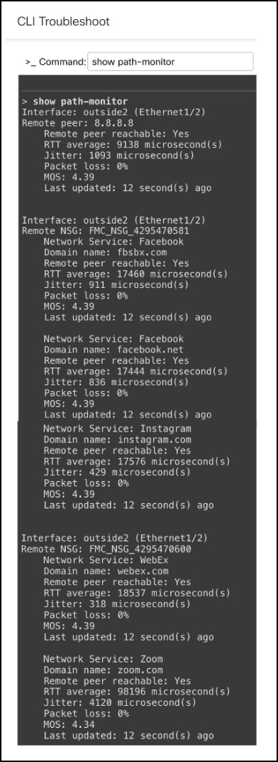
Verify Path Monitoring Configurations
Run the show path-monitor command to see the path monitoring configurations.
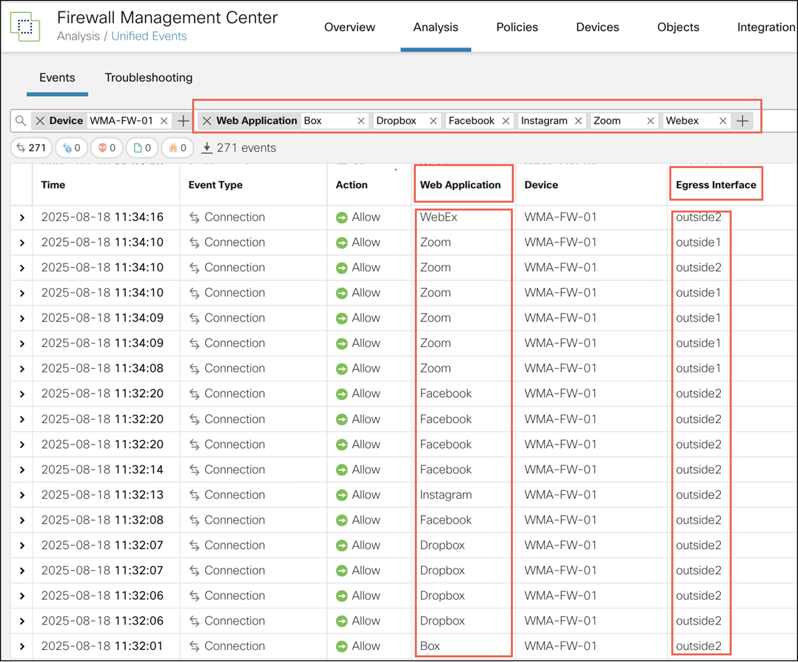
Verify Application Traffic Flow
Step 1. Choose Analysis > Unified Events.
Step 2. Customize the columns using the Column Picker icon. Select Web Application and Egress Interface and click Apply.
Step 3. Reorder the columns for ease of verification.
Step 4. Within the Web Application filter, enter Box, Dropbox, Facebook, Instagram, WebEx, Zoom, and click Apply. This page shows the egress interfaces selected by Threat Defense device for the various applications defined in the PBR policy.
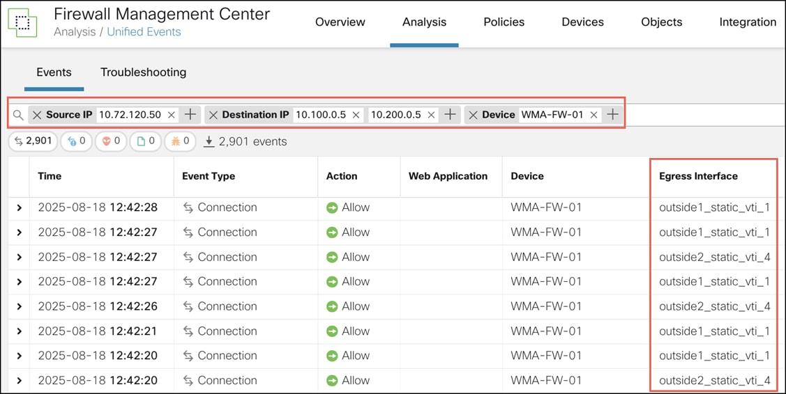
Step 5. Remove the Web Application filter.
Step 6. Within the filter, add Source IP as 10.72.120.50 (WMA-inside-nw) and Destination IP as 10.100.0.5 (NYC-internal-nw) and 10.200.0.5 (NNJ-internal-nw) to see the events for the traffic from the WMA LAN to the NYC and NNJ hubs.
Monitor SD-WAN Topologies and Application Traffic
You can monitor SD-WAN topologies and their application traffic using the SD-WAN Summary Dashboard (Overview > Dashboards > SD-WAN Summary). This dashboard helps you to:
● Identify issues with the underlay and overlay topologies.
● Troubleshoot VPN issues using the existing Health Monitoring, Device Management, and Site-to-Site Monitoring pages.
● Monitor application performance metrics of WAN interfaces. The Threat Defense steers application traffic based on these metrics.
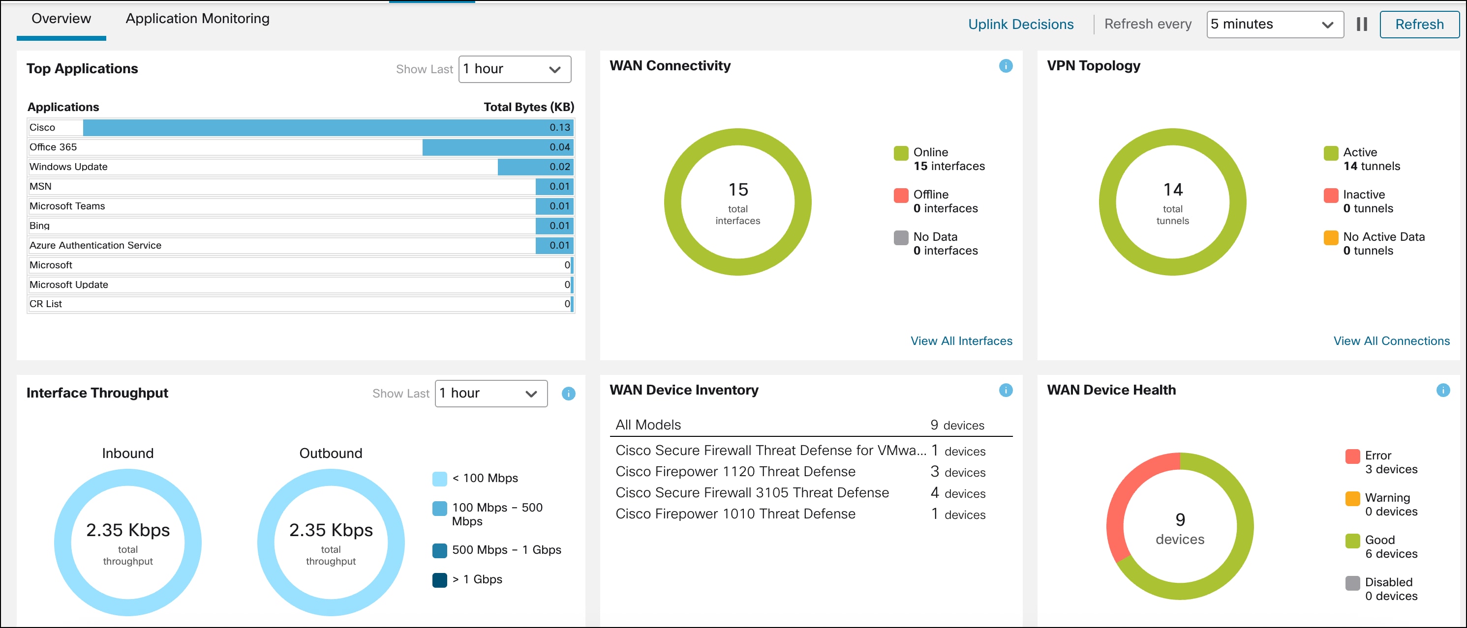
The Overview section has the following widgets:
● Top Applications: Displays the top 10 applications ranked according to throughput.
● WAN Connectivity: Provides consolidated information on the statuses of WAN interfaces.
● VPN Topology: Provides a summary of the site-to-site VPN tunnel statuses.
● Interface Throughput: Provides information about network-wide throughput utilization of WAN interfaces.
● Device Inventory: Lists all the managed WAN devices and groups them according to the model.
● WAN Device Health: Displays the device count according to the health of the WAN devices
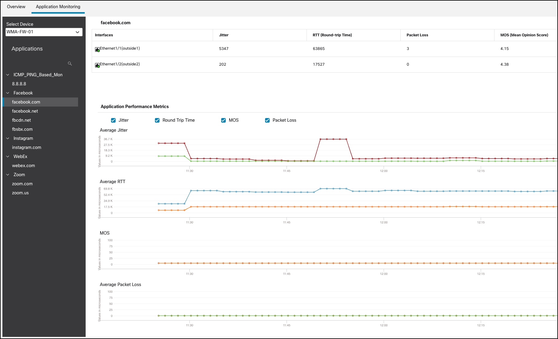
In the Application Monitoring section of the dashboard, you can select a WAN device and view the application performance metrics for the corresponding WAN interfaces. These metrics include Jitter, Round Trip Time (RTT), Mean Opinion Score (MOS), and Packet Loss.
For more information about the dashboard, see https://secure.cisco.com/secure-firewall/docs/sd-wan-summary-dashboard.
For more details on SD-WAN design and additional use cases, see Cisco Secure Firewall Threat Defense SD-WAN Design and Deployment Guide.