Integrate SASE and SSE Solutions with Cisco Secure Firewall Threat Defense
Available Languages
Bias-Free Language
The documentation set for this product strives to use bias-free language. For the purposes of this documentation set, bias-free is defined as language that does not imply discrimination based on age, disability, gender, racial identity, ethnic identity, sexual orientation, socioeconomic status, and intersectionality. Exceptions may be present in the documentation due to language that is hardcoded in the user interfaces of the product software, language used based on RFP documentation, or language that is used by a referenced third-party product. Learn more about how Cisco is using Inclusive Language.
- US/Canada 800-553-2447
- Worldwide Support Phone Numbers
- All Tools
 Feedback
 Feedback
Integrate SASE and SSE Solutions with Threat Defense
Secure Access Service Edge (SASE) brings network and security services closer to users and devices, using the cloud.
To improve security without changing the whole network, use Security Service Edge (SSE). It delivers important security functions from the cloud, making security simpler and improving the user experience.
Cisco SASE Solution: Secure Internet Traffic Using Cisco Umbrella and Threat Defense
Cisco Umbrella is a cloud-based secure internet gateway platform that provides multi-layered protection against internet threats. It integrates DNS layer security, SWG, cloud-delivered firewall, DLP, CASB, and threat intelligence to deliver highly scalable security for all branches. Internet-bound traffic from remote or on-prem users is automatically routed from the branches to the nearest Umbrella point of presence for inspection before access is granted or denied.
Cisco Firewall can integrate with Umbrella in two ways:
· Secure internet traffic for all branches with a consistent DNS policy.
· Secure internet traffic for all branches using Umbrella auto tunnel.
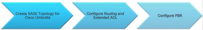
Workflow for Configuring Umbrella SASE Auto Tunnel
Prerequisites for Configuring Umbrella SASE Tunnels
● Management Center must be Version 7.3 or later.
● Threat Defense device must be Version 7.1 or later.
● Base license must be enabled with export-controlled features in the Management Center.
● Cisco Umbrella Secure Internet Gateway (SIG) Essentials subscription or a free SIG trial version must be available.
Configuration Steps:
● Log into Umbrella at http://login.umbrella.com, and obtain the required information (organization ID, Key and secret, API keys) to establish a connection to Cisco Umbrella. This configuration is explained later in this guide.
● Umbrella data center must be reachable from the Threat Defense device. See IPs associated with Umbrella data centers.
Network Topology for Umbrella SASE Auto Tunnel
In this example, we use Providence, RI (PRI-FW-01) branch with Firepower 1010 for the SASE integration.
For ease of understanding, we use only the New York City, NY (NYC) hub device in this example.
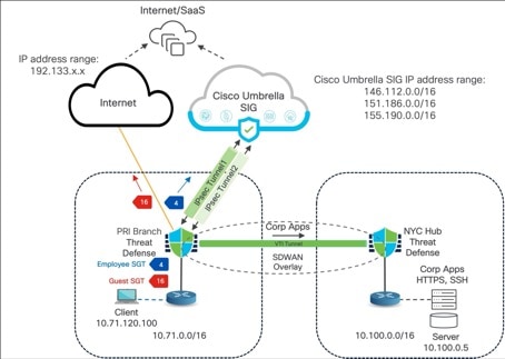
● PRI-FW-01 has an SD-WAN connection with the NYC hub device.
● PRI-FW-01 has an interface connected to the Internet.
● Using the Umbrella SASE Auto Tunnel wizard in the Management Center, we will configure two tunnels to Umbrella from PRI-FW-01.
● IPsec Tunnel1 is the primary tunnel to Umbrella.
● IPsec Tunnel2 is the secondary tunnel to Umbrella.
● Employees are assigned an SGT of 4 and guests are assigned an SGT of 16
Note: This SD-WAN architecture is not integrated with Cisco ISE. SGTs are assigned locally in Management Center; if you use Cisco ISE, define SGTs there.
● PBR policy for this example:
◦ Block traffic from 10.74.0.0/16 to 10.0.0.0/8 with SGT 4, so all Employee overlay traffic defaults to normal routing.
◦ Permit Employee DNS/HTTP/HTTPS traffic with SGT 4 to be routed to Umbrella SIG services for inspection and filtering.
◦ Permit all Guest traffic with SGT 16 to be routed directly out to the internet.
◦ All non-SGT traffic will automatically use normal routing.
● PRI-FW-01 interface details:
◦ Ethernet1/1 (outside1) is the underlay interface.
◦ Tunnel 1 (outside1_static_vti_1) and Tunnel 2 (outside1_static_vti_2) are static VTI interfaces under Ethernet1/1.
Map Management Center Umbrella Parameters and Cisco Umbrella API Keys
You must register Cisco Umbrella with the Management Center and configure the Umbrella parameters in the Management Center.
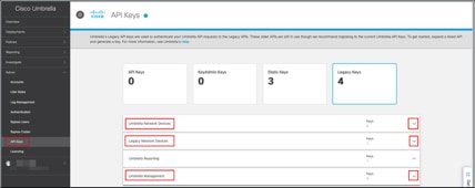
Step 1. Log in to Cisco Umbrella.
Step 2. Note the Organization ID from the URL.
In this example, the URL is https://dashboard.umbrella.com/o/abcde/#/overview. Here, abcde is the Organization ID.
Step 3. Choose Admin > API Keys > Legacy Keys.
Step 4. Expand the arrow corresponding to each API, then generate and copy the required API keys.
Step 5. Log in to Management Center.
Step 6. Choose Integration > Other Integrations > Cloud Services > Cisco Umbrella Connection to configure Cisco Umbrella connection parameters using the API keys.
Table 1. Mapping of Management Center Umbrella Parameters and Umbrella API Keys
| Management Center Parameter |
Cisco Umbrella API Keys |
| Network Device Key Network Device Secret |
Umbrella Network Devices |
| Legacy Network Device Token |
Legacy Network Devices |
| Management Key Management Secret |
Umbrella Management |
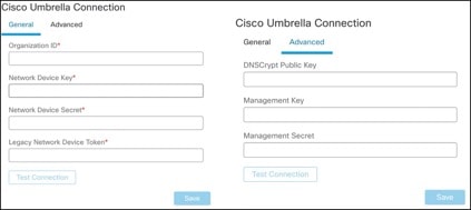
Note: DNScrypt Public Key is an optional parameter.
Step 7. After adding the organization ID, token, and keys, click Test Connection to check the API integration with Umbrella.
If the connection is fine, a Connection Successful message is displayed.
Configure a SASE Topology for Umbrella
High availability is achieved using different Umbrella data centers.
Step 1. Log in to the Management Center.
Step 2. Choose Devices > VPN > Site To Site.
Step 3. Click Add.
Step 4. Click the SASE Topology radio button to open the SASE topology wizard.
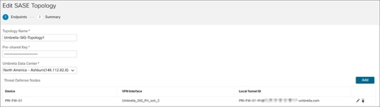
Step 5. In the Topology Name field, enter a unique topology name.
In this example, the name is Umbrella-SIG-Topology1.
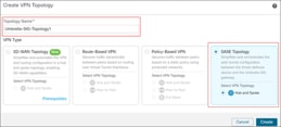
Step 6. Click Create.
Step 7. In the Pre-shared Key field, the wizard adds an auto-generated key according to the Umbrella PSK requirements.
The device and Umbrella share this secret key, and IKEv2 uses it for authentication. You can override the auto-generated key. If you want to configure this key, it must be between 16 and 64 characters in length, include at least one uppercase letter, one lowercase letter, one numeral, and have no special characters. Each topology must have a unique pre-shared key. If a topology has multiple tunnels, all the tunnels have the same pre-shared key.
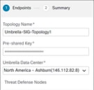
Step 8. From the Umbrella Data center drop-down list, choose a data center.
Step 9. Click Add to add a Threat Defense device as an endpoint in the SASE topology.
Step 10. In the Add Endpoint dialog box, configure these parameters:
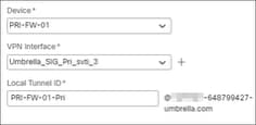
i. From the Device drop-down list, choose a Threat Defense device (PRI-FW-01).
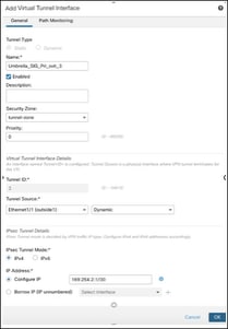
ii. From the VPN Interface drop-down list, click + to create a new static VTI interface.
iii. In the Add Virtual Tunnel Interface dialog box, you can view pre-populated default configurations. A few parameters must be configured as explained in the next steps.
iv. In the Name field, enter the name for the static VTI. In this example, it is Umbrella_SIG_Pri_svti_3.
v. From the Security Zone drop-down list, choose a security zone. In this example, it is tunnel-zone.
vi. From the Tunnel Source drop-down list, choose an interface. In this example, it is the underlay interface Ethernet1/1 (outside1) and set the value as Dynamic.
vii. In the IP Address area, select the Configure IP radio button and enter an IP for the static VTI interface. In this example, it is 169.254.2.5/30.
viii. Click OK.
Step 11. In the Local Tunnel ID field, enter a prefix for the local tunnel ID. In this example, it is PRI-FW-01-Pri.
The prefix can have a minimum of eight characters and a maximum of 100 characters. Umbrella generates the complete tunnel ID (<prefix>@<umbrella-generated-ID>-umbrella.com) after the Management Center deploys the tunnel on Umbrella. The Management Center then retrieves and updates the complete tunnel ID and deploys it on the Threat Defense device. Each tunnel has a unique local tunnel ID.
Step 12. Click Save.
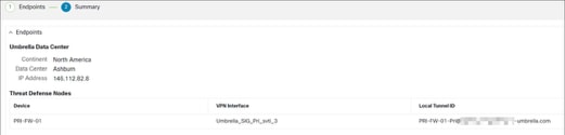
Step 13. Review the information.
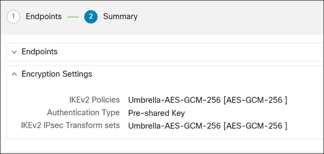
Step 14. Click Next to view the summary of the Umbrella SASE tunnel configuration.
- Endpoints pane: Displays the summary of the configured threat defense endpoints.
- Encryption Settings pane: Displays the encryption settings for the SASE tunnel.
Step 15. Check the Deploy configuration on threat defense nodes check box to trigger deployment of network tunnels to the Threat Defense device.
This deployment only occurs after the tunnels are deployed on Umbrella. Local tunnel ID is required for the threat defense deployment.
Step 16. Click Save to perform these actions:
- Saves the SASE topology in the Management Center.
- Triggers deployment of the network tunnels for the threat defense device to Umbrella.
- Triggers deployment of the network tunnels to the threat defense device, if the option is enabled. This action deploys all the updated configurations and policies, including non-VPN policies, since the last deployment on the device.
- Opens the Cisco Umbrella Configuration dialog box and displays the status of the tunnel deployment on Umbrella.
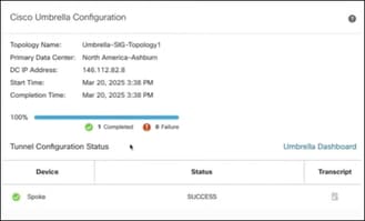
Step 17. Click Umbrella Dashboard to view the network tunnels in Umbrella.
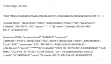
Step 18. Click the Transcript icon to view transcript details such as the APIs, request payload, and the response received from Umbrella.
Step 19. Repeat Step 3 to Step 18 to configure the secondary tunnel to Umbrella (Umbrella-SIG-Topology2).
Step 20. Follow these guidelines when you configure the secondary tunnel:
- Choose a different Umbrella data center for this tunnel.
- Create a new static VTI interface (Umbrella_SIG_Sec_svti_4).
- Choose the Tunnel Source as Ethernet1/1 (outside1).
- Configure a new Local Tunnel ID (PRI-FW-01-Sec).
Configure Security Group Tags
A Security Group Tag (SGT) object specifies a single SGT value. You can use SGT objects in rules to control traffic with SGT attributes that are not assigned by Cisco ISE.
Note: You cannot create custom SGT objects if you use Cisco ISE as an identity source.
Step 1. Choose Objects > Object Management.
Step 2. In the left pane, click External Attributes > Security Group Tag.
Step 3. Click Add Security Group Tag.
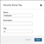
Step 4. In the Name field, enter a name. In this example, we use Employee.
Step 5. (Optional) In the Description field, enter the description.
Step 6. In the Tag field, enter a single SGT.
Step 7. Click Save. An SGT named Employee with a tag value of 4 is created.
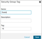
Step 8. Repeat Step 3 to Step 7 to create a Guest SGT of value 16.
Configure Extended ACL Objects
You must configure extended ACLs for applications to direct their traffic to the Internet through different egress interfaces using PBR.
In this example, we create ACLs with these rules:
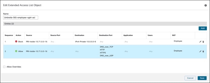
● Block traffic from 10.71.0.0/16 to 10.0.0.0/8 with SGT 4, so that all employee overlay traffic uses normal routing.
● Permit employee DNS/HTTP/HTTPS traffic with SGT 4 to be routed to Umbrella SIG services for inspection and filtering.
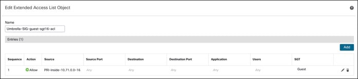
● Permit all guest traffic with SGT 16 to be routed directly out to the internet.
Step 1. Choose Objects > Object Management.
Step 2. In the left pane, click Access Lists > Extended.
Step 3. Click Add Extended Access List.
Step 4. In the New Extended ACL Object dialog box, configure these parameters:
i. In the Name field, enter a name for the object (Umbrella-SIG-employee-sgt4-acl).
ii. Click Add to create a new extended access list.
iii. From the Action drop-down list, choose Block.
iv. Click the Network tab.
v. Search for PRI-inside-10.71.0.0-16, and click Add to Source.
vi. Search for IPv4-Private- 10.0.0.0-8, and click Add to Destination.
vii. Click the Security Group Tag tab.
viii. Search for Employee, and click Add.
ix. Click Save.
x. Click Add to add the next extended access list.
xi. From the Action drop-down list, choose Allow.
xii. Click the Network tab.
xiii. Search for PRI-inside-10.71.0.0-16, and click Add to Source.
xiv. Search for any, and click Add to Destination.
xv. Click the Security Group Tag tab.
xvi. Search for Employee, and click Add.
xvii. Click Save.
Step 5. Click Save. The extended ACL is displayed in the Extended ACL page.
Step 6. Create an extended access list (Umbrella-SIG-guest-sgt16-acl) with Source network as PRI-inside-10.71.0.0-16 and SGT as Guest.
Configure a Static Route
You must configure a static default route for Cisco Umbrella with the next hop IP address as the other end of the static VTI tunnel 169.254.2.x.
Step 1. Choose Devices > Device Management, and edit the Threat Defense device. In this example, we use PRI-FW-01.
Step 2. Click the Routing tab.
Step 3. In the left pane, click Static Route.
Step 4. Click Add Route.
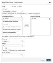
Step 5. In the Add Static Route Configuration dialog box, configure these parameters:
i. Click the IPv4 radio button.
ii. From the Interface drop-down list, choose Umbrella_SIG_Pri_svti_3.
iii. Select the Network as any-ipv4.
iv. In the Gateway field, enter 169.254.2.2. This IP address is derived from the tunnel IP address subnet defined in the Configure a SASE Topology for Umbrella section.
v. In the Metric field, enter a value greater than 1, because 1 has been used for the underlay network. In this example, it is 10.
vi. Click OK.
Step 6. Configure another static route for the secondary tunnel to Umbrella.
i. From the Interface drop-down list, choose Umbrella_SIG_Sec_svti_4.
ii. Select the Network as any-ipv4.
iii. In the Gateway field, enter 169.254.2.6.
iv. In the Metric field, enter a value of 11.
v. Click OK.
Step 7. Click Save.
Configure a Policy Based Routing Policy
Step 1. Choose Devices > Device Management.
Step 2. Click the Edit icon adjacent to the device (PRI-FW-01).
Step 3. Click the Routing tab.
Step 4. In the left pane, click Policy Based Routing.
Step 5. Click Add.
Step 6. In the Add Policy Based Route dialog box, from the Ingress Interface drop-down list, choose an interface.
Note: Only interfaces that have logical names and that belong to a global virtual router are listed in the drop-down.
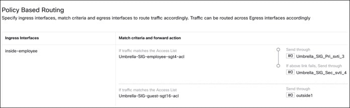
In this example, the ingress interface is inside-employee.
Step 7. Click Add to specify a match criteria and a forward action in the policy.
Step 8. In the Add Forwarding Actions dialog box, configure these parameters:
i. From the Match ACL drop-down list, choose an extended ACL (Umbrella-SIG-employee-sgt4-acl).
ii. From the Send To drop-down list, choose Egress Interfaces.
iii. From the Interface Ordering drop-down list, choose Order.
iv. In the Available Interfaces box, click + adjacent to an interface to add the selected egress interface. In this example, select Umbrella_SIG_Pri_svti_3 and Umbrella_SIG_Sec_svti_4.
v. Click Save.
Step 9. Click Add to configure a forwarding action for the guest traffic.
Step 10. In the Add Forwarding Actions dialog box, configure these parameters:
i. From the Match ACL drop-down list, choose an extended ACL (Umbrella-SIG-guest-sgt16-acl).
ii. From the Send To drop-down list, choose Egress Interfaces.
iii. From the Interface Ordering drop-down list, choose Interface Priority.
iv. In the Available Interfaces box, click + adjacent to an interface to add the selected egress interface. In this example, select outside1.
Note: Ensure that you have an access policy and a NAT policy for your Internet traffic.
Step 11. Click Save.
Here's an example of the configuration.
Step 12. Deploy the PBR policy on the device.
Verify SASE Umbrella Tunnel Deployment
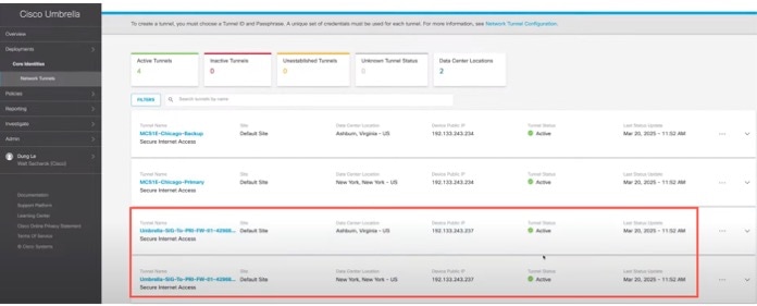
View SASE Tunnels in Umbrella
To view the SASE tunnel in Umbrella, log in to Cisco Umbrella and choose Deployments > Core Identities > Network Tunnels. The network tunnels from the Threat Defense device to Umbrella is displayed.
View SASE Tunnels in Management Center
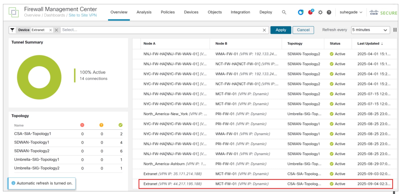
To view the SASE tunnels in the Site To Site VPN dashboard in the Management Center, choose Overview > Dashboard > Site to Site VPN.
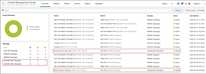
To see more details about each tunnel:
Step 1. For each tunnel, hover your cursor over a topology and click the View (![]() ) icon.
) icon.
Step 2. Click the CLI Details tab.
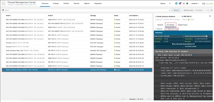
Step 3. Click Maximize View. You can view the output of the following commands:
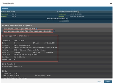
● show crypto ipsec sa peer: Shows the number of packets that are transmitted through the tunnel. In this example, the specified peer IP is 146.112.82.8, which allows us to view the exact tunnel statistics for SASE, as there are multiple tunnels involved.
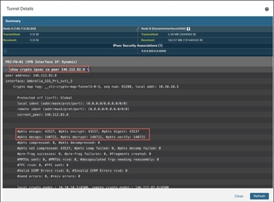
● show vpn-sessiondb detail l2l filter ipaddress: Shows more detailed data for the VPN connection.
Verify Traffic to Umbrella
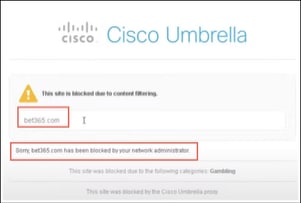
From a client with IP address 10.71.120.100 (See Figure 1. for details), when you log in as an employee with SGT 4, you can browse the Internet. If you try to access any sites that are blocked such as betting sites, you will notice that Umbrella blocks these sites.
If you verify the IP address of the client, you can see that the assigned IP address is 155.190.18.5, which is within the Umbrella SIG IP address range: 155.190.0.0/16. Here, the employee will be able to access the internet using the Umbrella SIG IP range.
From the client with the IP address 10.71.120.100, when you log in as a guest with SGT 16, you can verify that you cannot access the internal network. However, you can access the internet and blocked sites. The guest will be able to access the internet directly without going through Umbrella.
Verify Traffic Flow in Management Center
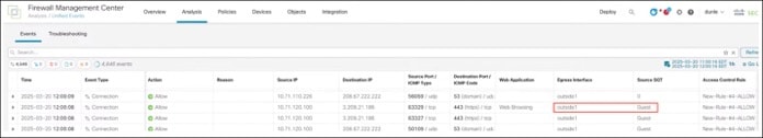
Step 1. Choose Analysis > Unified Events.
Step 2. Within the Source SGT filter, enter Employee.
Traffic with source SGT 4 goes through the Umbrella_SIG_Pri_svti_3 interface.
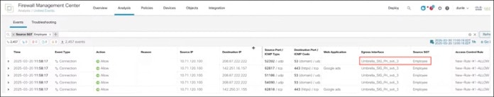
Traffic with source SGT 16 goes through the outside1 interface.
Verify Traffic Flow in Umbrella
The Activity Search report includes details about traffic from Firewall that has been allowed or blocked by Umbrella.
Choose Reporting > Core Reports > Activity Search.
Cisco SSE Solution: Secure Branch Using Cisco Secure Access and Threat Defense
Cisco Secure Access is Cisco's cloud-based platform that provides you with multiple levels of defense against internet-based threats. Connect securely to the internet, integrate with SaaS apps, and your private digital resources, whether you connect from your organization's network or roaming off a network.
Secure Firewall seamlessly integrates with Secure Access for various use cases primarily for:
● Enhanced visibility and control for remote users: Secure Access extends security policies beyond the physical branch perimeter to protect users regardless of location, providing the same level of threat protection and access controls equivalent to on-premises, creating consistent security enforcement.
● Simplified security architecture: Secure Access integrates with a Threat Defense device to consolidate multiple security functions such as Secure Web Gateway, CASB, DLP, and cloud firewall. This consolidation provides a single-pane-of-glass experience for policy management across branch deployments and cloud-delivered security services.
Workflow for Integrating Secure Access with Threat Defense
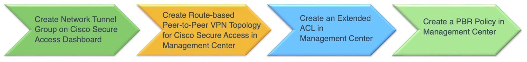
This section outlines the configuration process for Cisco Secure Access integration, which primarily involves setting up manual tunnels from the Threat Defense platform to Cisco Secure Access.
1. Create a Network Tunnel Group on the Cisco Secure Access dashboard.
This initial step involves creating the tunnel group and gathering the necessary configuration details from the Cisco Secure Access Dashboard.
2. Configure the tunnel using the Route-Based VPN wizard in the Management Center.
After creating the network tunnel group on Cisco Secure Access, proceed to the Management Center to establish the route-based VPN topology connecting to Cisco Secure Access.
3. Create an extended Access Control List (ACL).
This ACL defines the specific DNS and web traffic intended for routing through the tunnel to Cisco Secure Access. This approach aligns with the Cisco Umbrella integrations.
4. Create a policy-based routing (PBR) policy
Use the previously created ACL within policy-based routing to direct the defined DNS and web traffic through the tunnel to Cisco Secure Access for security inspection.
5. Verification and Troubleshooting
Similar to Cisco Umbrella integrations, verification and troubleshooting commands are available. A key difference is the ability to log into the Cisco Secure Access Dashboard to check tunnel status and view additional statistics.
The integration of Cisco Secure Access is supported with Management Center Version 7.1 and later. It also allows for the manual creation of tunnels for Cisco Secure Access.
Prerequisites for Integrating Secure Access with Threat Defense
● Management Center must be Version 7.1 and later.
● Threat Defense device must be Version 7.1 and later.
● Base license must be enabled with export-controlled features in the Management Center.
● Cisco Secure Access Essentials subscription license must be available.
Integrate Cisco Secure Access with Threat Defense for Branch Network Security
In this example, we use the this topology for Secure Access integration for network security of the branch:
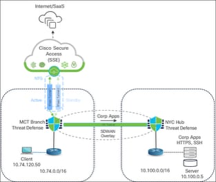
● MCT Branch Setup: The MCT branch uses a single Threat Defense device, which already has an established SD-WAN overlay tunnel. This tunnel provides connectivity to the internal resources at the New York City (NYC) hub site, where corporate applications reside (10.100.0.0/16).
● Tunnels to Cisco Secure Access: For secure internet access and cloud security enforcement, two IPsec tunnels are configured from the MCT branch Threat Defense to Cisco Secure Access. One tunnel is designated as active, while the other serves as a standby for redundancy, ensuring high availability in case of a primary connection failure.
● Policy-Based Routing (PBR): The core of this integration lies in the Policy-Based Routing (PBR) configuration on the device, which explicitly dictates how different types of traffic are handled:
◦ Internal Traffic (Overlay Traffic): A PBR rule is set up to block traffic originating from the MCT branch's 10.74.0.0/16 IP block and directed to internal networks (represented as 10.0.0.0/8, which includes the 10.100.0.0/16 corporate application subnet at the NYC Hub). This explicit block ensures that all internal or "overlay traffic" bypasses the PBR policy and reverts to normal routing. This traffic then utilizes the existing SD-WAN overlay tunnels to access internal corporate applications and services.
◦ Internet Traffic (SSE Services): Conversely, a second PBR rule is configured to permit all other traffic. This ensures that any traffic not destined for internal corporate networks (internet-bound traffic) is explicitly routed through the established IPsec tunnels to Cisco Secure Access. Cisco Secure Access, acting as a Security Service Edge (SSE) solution, provides comprehensive cloud-based security capabilities such as inspection, filtering, DNS security, Layer 3/Layer 4 firewalling, and Secure Web Gateway services. The primary intent is to ensure all internet-bound traffic originating from the branch is secured and thoroughly inspected by the cloud security platform.
Configure a Network Tunnel Group
Step 1. Sign in to Secure Access through the Cisco Security Cloud Sign On portal.
Step 2. In Security Cloud Sign On, enter the email address where you received the invitation to join a Secure Access organization and click SIGN IN.
Your Secure Access account and the Security Cloud sign on account must use the same email address.
Step 3. Choose to Connect > Network Connections > Network Tunnel Groups.
Step 4. Click Add.
Step 5. Enter the General Settings for your tunnel group:
- Tunnel Group Name: Enter a name. In this example, we use MCT-FW-01.
- Region: In this example, we choose US (Virginia).
- Device Type: In this example, we choose FTD.
Step 6. Click Next.
Step 7. In the Tunnel ID and Passphrase area, configure the tunnel ID and passphrase for the MCT-FW-01 device that will be used to connect to this tunnel group:
- Tunnel ID Format: In this example, we use the name you gave the tunnel group in Step 2, MCT-FW-01. The format is <tunnel name>@<org><hub>.sse.cisco.com.
- Passphrase: Enter a passphrase for the tunnel between 16 and 64 characters in length. The passphrase must contain at least one upper case letter, one lower case letter, and one number. The passphrase cannot include any special characters.
- Reenter your passphrase to confirm.
Step 8. Click Next to continue.
Step 9. In the Routing area, configure the following:
When configuring Cisco Secure Access (SSE) for branch secure internet access, there are three primary routing options: Enable NAT/Outbound Only, Static routing, and Dynamic routing.
In this example, we will check the Enable NAT/Outbound Only checkbox. Use this option to provide secure internet access to users behind the MCT-FW-01 Threat defense device.
The dynamic routing method is specifically used when dealing with secure private application access.
Step 10. Click Save.
Step 11. In the Data for Tunnel Setup area, review and save the information for use when setting up your network tunnel devices.
Note: This is the only time that your passphrase is displayed.
Step 12. Click Download CSV to save your tunnel setup information. You can use the information to configure and deploy a tunnel in the Threat Defense device from the Management Center.
Step 13. Click Done.
The tunnel group is created without tunnels in the Network Tunnels area.
Create a VPN Tunnel on Threat Defense
Step 1. In the Management Center, choose Devices > Device Management.
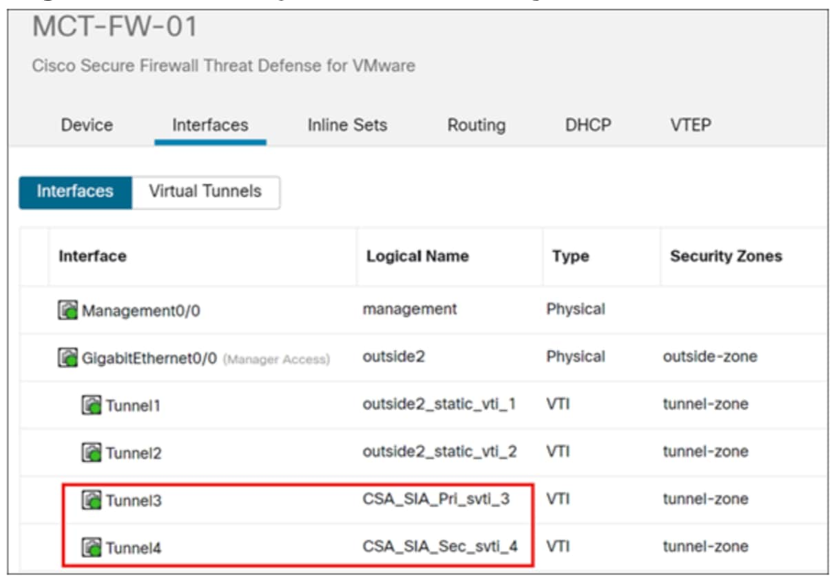
Step 2. Click MCT-FW-01.
In this example, we have already created two overlay tunnels for the SDWAN overlay towards NYC-FW-HA and NNJ-FW-HA.
We will create two additional tunnels directed towards Cisco Secure Access.
Step 3. Choose Devices > Site To Site.
Step 4. Click Add.
Step 5. In the Topology Name field, specify a name. In this example, the name is CSA-SIA-Topology1.
Step 6. Click Route-Based VPN and select Peer to Peer. Although the default selection for this topology is typically Hub and Spoke, a different approach is utilized in this example. We choose a Peer to Peer connection with two devices.
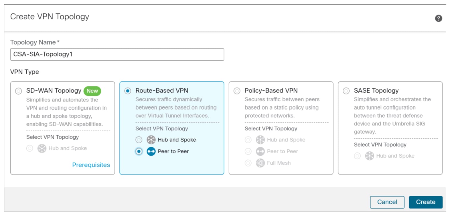
Step 7. Click Create.
For this VPN setup, only IKEv2 is supported, and it is selected by default.
Configure Endpoints
Step 1. In the Point to Point tab, choose MCT-FW-01 device.
Step 2. Click + to add a new static VTI.
The Add Virtual Tunnel Interface dialog box is displayed.
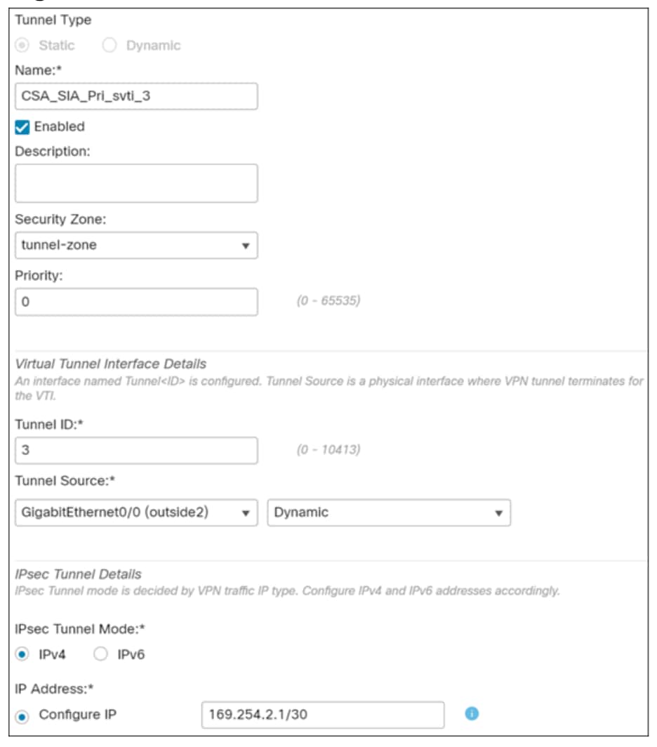
i. In the Name field, enter a name. In this example, the name of the interface is CSA_SIA_Pri_svti_3.
ii. When configuring a static virtual tunnel interface (VTI) for Cisco Secure Access integration, the process involves selecting the Security Zone as tunnel zone and use default settings for priority and tunnel ID. From the Security Zone drop-down list, choose tunnel-zone.
iii. From the Tunnel Source drop-down list, choose the tunnel source interface. In this example, we choose GigabitEhternet0/0 (outside2), and it is configured as Dynamic because it uses DHCP for IP address assignment.
iv. In the IPsec Tunnel Mode, we choose IPv4 and in the Configure IP field, we use the provided IP address.
v. Click OK. The VTI tunnel is created. The Tunnel Source IP Address field obtains the outside interface IP address.
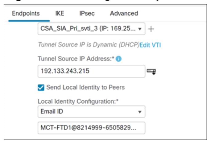
Step 3. Check the Send Local Identity to Peers check box.
Step 4. In the Local Identity Configuration field, we choose Email.
Step 5. Enter the Primary Tunnel ID address found in CSV file downloaded from Secure Access.
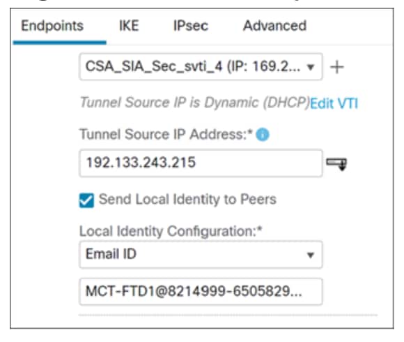
Step 6. Click + to add a Backup VTI.
Step 7. In the Name field, enter a name. In this example, the name of the interface is CSA_SIA_Sec_svti_4.
i. When configuring a static virtual tunnel interface (VTI) for Cisco Secure Access integration, the process involves selecting the tunnel zone and leaving both the priority and the tunnel ID at their default settings. From the Security Zone drop-down list, choose tunnel-zone.
ii. From the Tunnel Source drop-down list, choose the tunnel source interface. In this example, we choose GigabitEhternet0/0 (outside2), and it is configured as Dynamic because it uses DHCP for IP address assignment.
iii. In the IPsec Tunnel Mode, we choose IPv4 and in the Configure IP field, we use the provided IP address.
iv. Click OK. The VTI tunnel is created. The Tunnel Source IP Address field obtains the outside interface IP address. In this example, we have 169.254.3.1/30.
v. Click OK. This IP address is important for subsequent routing configurations, specifically for directing traffic to the other end of the tunnel.
Step 8. Check the Send Local Identity to Peers check box.
Step 9. In the Local Identity Configuration field, we choose Email.
Step 10. Enter the Secondary Tunnel ID address found in CSV file downloaded from Secure Access.
Step 11. In the Node B area, choose Extranet from the Device drop-down list.
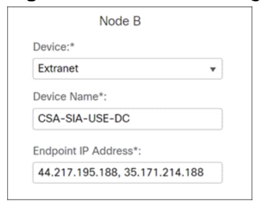
Step 12. In the Device Name field, enter a name. In this example, we will specify CSA-USE-DC.
Step 13. In the Endpoint IP Address field, enter the Primary Data Center IP Address, followed by the Secondary Data Center IP Address separated by a comma. This information can be found in the CSV file downloaded from Secure Access in step 12 of the “Add a Network Tunnel Group” topic.
Configure IKE Settings
Step 1. Click the IKE tab to configure the preshared key for IKEv2.
Step 2. From the Authentication Type drop-down list, choose Pre-shared Manual Key.
Step 3. Manually assign the pre-shared key for this VPN. Specify the Key and then reenter the same to Confirm Key.
The keys we enter are not displayed, so make sure to remember them.
Note: In the Advanced tab, under ISAKMP Settings, choose Do not check from the Peer Identity Validation drop-down list and do not alter the other settings. The remaining settings must have their default values.
Step 4. Click Save. The topology has been created, but there is no tunnel because we haven't pushed the configuration.
Create an Extended Access List
Step 1. In the Management Center, choose Objects > Object Management.
Step 2. Expand Access List and click Extended.
Step 3. Click Add Extended Access List.
The New Extended Access List Object dialog box appears.
Step 4. In the Name field, enter a name for the object. In this example, we enter CSA-SIA-acl.
Step 5. Click Add to add a rule.
The first rule handles the internal traffic. Any traffic originating from the 10.74.0.0/16 IP block, which is allocated to the MCT branch, and directed to 10.0.0.0/8 internal network (representing corporate applications), will "drop out of the policy". This implies that such internal or overlay traffic is explicitly excluded from these PBR rules and will instead be routed through "normal routing" or "topology-driven routing," leveraging the existing SD-WAN overlay for its routing requirements.
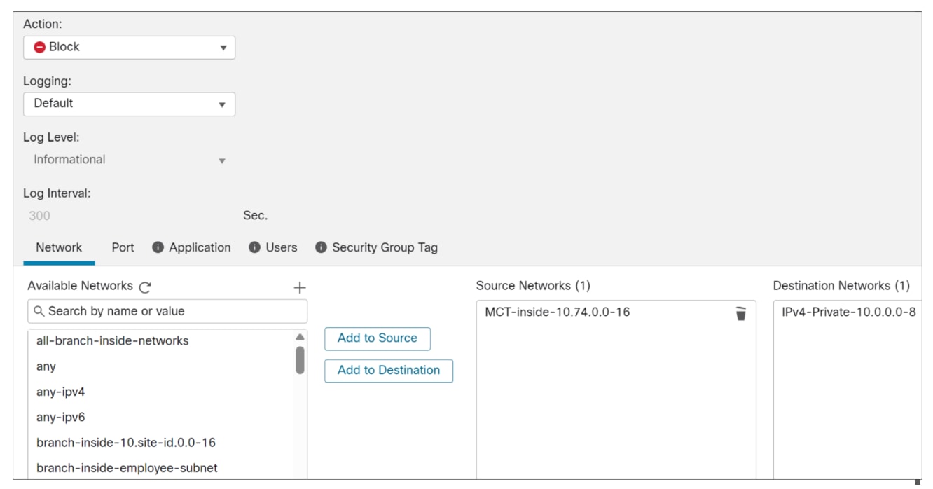
i. Action: Block
ii. Logging: Default
iii. Source Networks: MCT-inside-10.74.0-16
iv. Destination Networks: IPv4-Private-10.0.0.0-8
v. Click Add.
Step 6. Click Add to add another rule.
Any traffic originating from the 10.74.0.0/16 block that is not directed toward the internal 10.0.0.0/8 network is categorized as internet traffic. This internet-bound traffic is then routed directly to Cisco Secure Access. This ensures that all external traffic from the MCT branch undergoes essential SSE services, including inspection and filtering, provided by Cisco Secure Access before proceeding to its external destination.
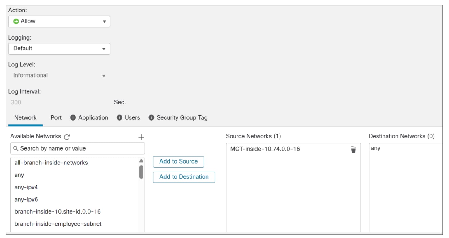
i. Action: Allow
ii. Logging: Default
iii. Source Networks: MCT-inside-10.74.0-16
iv. Destination Networks: any
v. Click Add.
Step 7. Click Save.
The extended ACL is created.
In this example, we will not create a static route, as we intend to demonstrate an alternative method for policy-based routing. While static routing is an option, we will use a different approach.
Create Policy-Based Routing
Step 1. In the Management Center, choose Devices > Device Management.
Step 2. Click the MCT-FW-01 device.
The two tunnels have been created, but they are not yet operational.
Step 3. Click the Routing tab.
Step 4. Click Policy Based Routing and click Add.
The Add Policy Based Route dialog box is displayed.
Step 5. From the Ingress Interface drop-down list, choose the ingress interface. In this example, we choose inside-employee.
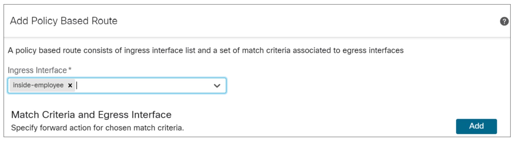
Note: The Policy-Based Routing rules on the Threat Defense devices are applied to the traffic as it enters an interface on a device.
Step 6. Click Add.
Step 7. From the Match ACL drop-down list, choose the extended access control list object that identifies the traffic you want to use for policy-based routing. The ACL object is predefined in the Configure Extended List Object section. In this example, we choose CSA-SIA-acl.
Step 8. From the Send To drop-down list, choose IP Address to specify the IPv4 next hop address.
Step 9. In the IPv4 Addresses field, specify the addresses. The next hop is the IP address of tunnels on the Cisco Secure Access. In this example, we enter 169.254.2.2, 169.254.3.2.
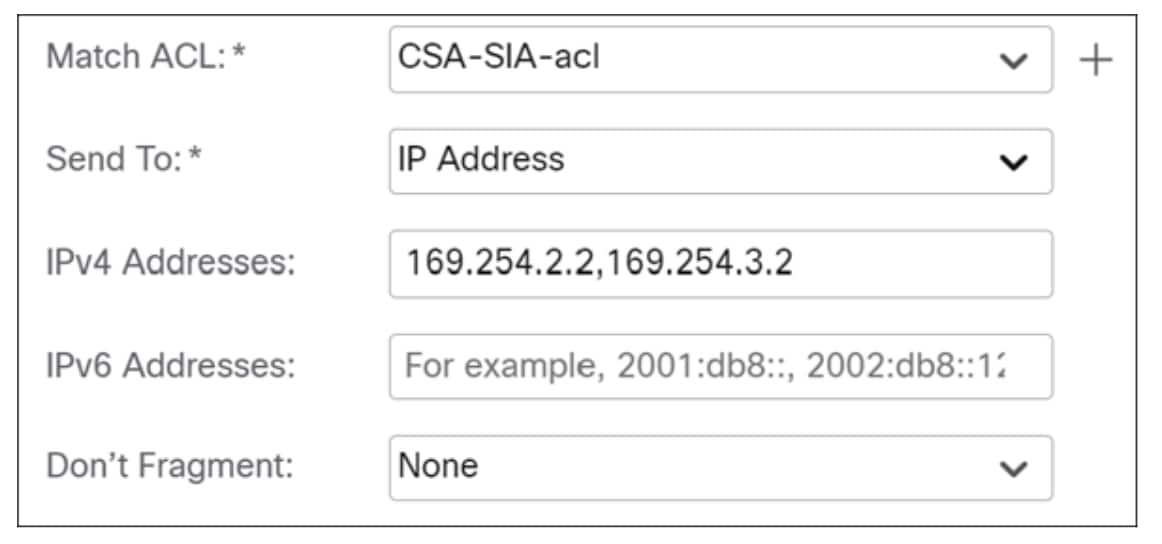
The next hop for the primary tunnel is configured as 169.254.2.2, which resides on the Cisco Secure Access side, while 169.254.2.1 is on the firewall's side of the primary tunnel. If the primary tunnel goes down, traffic is automatically redirected to the secondary tunnel, with its next hop at 169.254.3.2, also located on the Cisco Secure Access side.
Step 10. Click Save.
Deploy Changes to Device
Step 1. Click Deploy.
Step 2. Check the MCT-FW-01 check box and click Deploy All.
Verify Tunnels on Secure Access
Step 1. Sign in to Secure Access through the Cisco Security Cloud Sign On portal.
Step 2. In Security Cloud Sign On, enter the email address where you received the invitation to join a Secure Access organization and click SIGN IN.
Your Secure Access account and the Security Cloud sign on account must use the same email address.
Step 3. Choose Connect > Network Connections > Network Tunnel Groups.
Step 4. Click the MCT-FW-01 tunnel group.
Step 5. In the Network Tunnels area, the primary and secondary tunnels will be displayed. The Primary1 tunnel originates from the branch's outside2 interface and is destined for the primary Cisco Secure Access data center, while the Secondary1 tunnel also originates from the branch’s outside2 interface and connects to a secondary data center, serving as a standby for continuous connectivity.
View Access Policy on Secure Access
Note: This document serves as a design guide. The access policies referenced herein are assumed to be already configured within Cisco Secure Access. Detailed steps for policy creation are not covered in this guide.
Step 1. Choose Connect > Policy > Access Policy.
The first rule mct74-to-internet-block-web-categories ensures that any traffic originating from MCT site 74 destined for the internet will be subjected to security controls, specifically blocking gambling sites. This is a function of URL filtering or Secure Web Gateway (SWG) services provided by Cisco Secure Access. The intent is to apply security policies such as inspection and filtering to internet-bound traffic from the branch.
The second rule mct74-to-internet-block-ping-8.8.8.8 drops any traffic from MCT site 74 that is destined to the IP address 8.8.8.8.
The third rule mct74-to-internet-permit-all allows all other internet traffic, not explicitly blocked or dropped by the preceding rules, to pass through Cisco Secure Access for further SSE services.
Note: User traffic is first subjected to access control policies and inspection on MCT-FW-01. Only traffic that is allowed by these policies is then forwarded to Secure Access for further inspection.
Verify Connectivity Using CLI
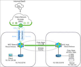
For testing purposes, a client with an IP address 10.74.120.50 (according to the above figure) is used. The initial test involved verifying traffic flow by attempting to access a server located at 10.100.0.5 in the New York data center.
C:\Users\user\>ipconfig
Ethernet adapter Main NIC:
Connection-specific DNS Suffix
IPv4 Address : 10.74.120.50
Subnet Mask : 255.255.255.0
Default Gateway : 10.74.120.1
C:\Users\user> ping 10.100.0.5
Pinging 10.100.0.5 with 32 bytes of data:
Reply from 10.100.0.5: bytes=32 time=2ms TTL=252
Reply from 10.100.0.5: bytes=32 time=2ms TTL=252
Reply from 10.100.0.5: bytes=32 time=2ms TTL=252
Reply from 10.100.0.5: bytes=32 time=2ms TTL=252
Ping statistics for 10.100.0.5:
Packets: Sent 4, Received = 4, Lost = 0 (0% loss),
Approximate round trip times in milli-seconds:
Minimum = 2ms, Maximum = 3ms, Average = 2ms
According to the defined policy:
● ping request to 8.8.8.8 should be blocked.
● ping request to 8.8.4.4 should be successful
● ping request to cisco.com should be successful
Run the test for the above IPs and urls to validate policy evaluation.
C:\Users\user>ping 8.8.8.
Pinging 8.8.8.8 with 32 bytes of data:
Request timed out.
C:\Users\user>ping 8.8.4.4
Pinging 8.8.4.4 with 32 bytes of data:
Reply from 8.8.4.4: bytes=32 time=2ms TTL=45
Reply from 8.8.4.4: bytes=32 time=2ms TTL=45
Reply from 8.8.4.4: bytes=32 time=2ms TTL=45
Reply from 8.8.4.4: bytes=32 time=2ms TTL=45
Ping statistics for 8.8.4.4:
Packets: Sent 4, Received = 4, Lost = 0 (0% loss),
Approximate round trip times in milli-seconds:
Minimum = 13ms, Maximum = 14ms, Average = 13ms
C:\Users\user>ping cisco.com
Pinging cisco.com [72.163.4.185] with 32 bytes of data:
Reply from 72.163.4.185: bytes=32 time=2ms TTL=38
Reply from 72.163.4.185: bytes=32 time=2ms TTL=38
Reply from 72.163.4.185: bytes=32 time=2ms TTL=38
Reply from 72.163.4.185: bytes=32 time=2ms TTL=38
Ping statistics for 72.163.4.185:
Packets: Sent 4, Received = 4, Lost = 0 (0% loss),
Approximate round trip times in milli-seconds:
Minimum = 48ms, Maximum = 49ms, Average = 48ms
Test Secure Access SWG Policies
To verify the Secure Web Gateway (SWG) filtering capabilities, conduct the following tests:
● Permit Web Access: Access to e-commerce (shopping) website (www.amazon.com) and site for purchasing vehicles (www.ford.com) was successful. This indicates that the traffic flows are permissible through SWG.
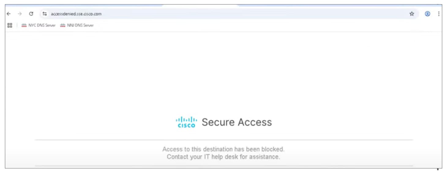
● Block Web Access: Access to a gambling website (www.bet365.com) is blocked. This confirms the effective enforcement of URL filtering policies.
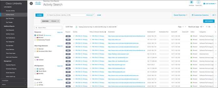
View the Activity Search Report in Secure Access
The Activity Search report includes full details about the Firewall requests that have been allowed or blocked by an access policy rule.
Step 1. In the Secure Access application, choose Monitor > Activity Search.
You can see the traffic originating from MCT-FW-01. This activity includes both allowed and blocked traffic.
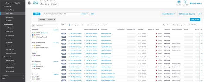
Step 2. In the Response filter, check the Blocked check box to see the blocked activities.
You can see that the gambling site (www.bet365.com) and ping to 8.8.8.8 is blocked.
View Tunnel Status on Management Center
Step 1. In the Management Center, choose Overview > Dashboards > Site to Site VPN.
Step 2. Click the View full information (![]() ) icon beside Extranet tunnel to Cisco Secure Access.
) icon beside Extranet tunnel to Cisco Secure Access.
Step 3. Click the CLI Details tab and expand “show crypto ipsec sa peer” command.
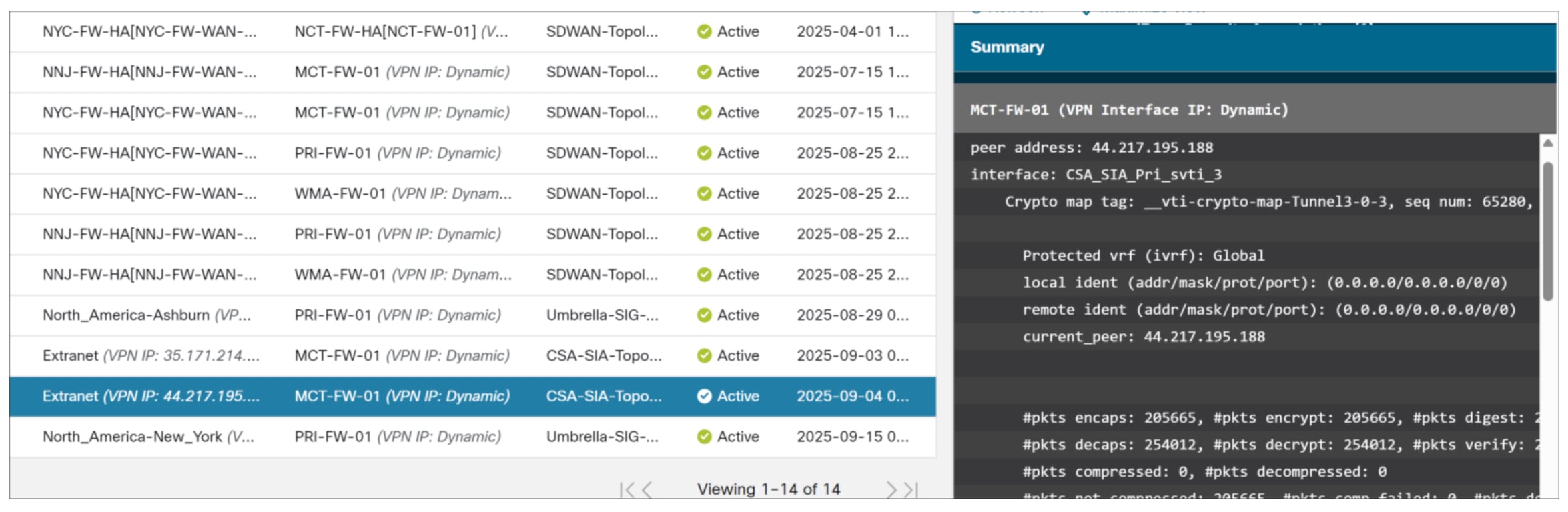
Step 4. You can observe packet encryption and decryption as a verification that the tunnel is up and allowing traffic.
For more details on SD-WAN design and additional use cases, see Cisco Secure Firewall Threat Defense SD-WAN Design and Deployment Guide.