Deploy an SD-WAN Overlay Using Cisco Secure Firewall Management Center
Available Languages
Bias-Free Language
The documentation set for this product strives to use bias-free language. For the purposes of this documentation set, bias-free is defined as language that does not imply discrimination based on age, disability, gender, racial identity, ethnic identity, sexual orientation, socioeconomic status, and intersectionality. Exceptions may be present in the documentation due to language that is hardcoded in the user interfaces of the product software, language used based on RFP documentation, or language that is used by a referenced third-party product. Learn more about how Cisco is using Inclusive Language.
- US/Canada 800-553-2447
- Worldwide Support Phone Numbers
- All Tools
 Feedback
 Feedback
Deploy SD-WAN Overlay Using SD-WAN Wizard
Management Center allows you to easily configure VPN tunnels and routing configuration between your centralized headquarters (hubs) and remote branch sites (spokes) using the new SD-WAN wizard. When it comes to implementing route-based VPN in a hub and spoke topology, Dynamic Virtual Tunnel Interface (DVTI) is configured on the hub and SVTI (Static Virtual Tunnel Interface) is configured on the spoke.
Benefits of Using SD-WAN Wizard
● Simplifies and automates the VPN and routing configuration of your SD-WAN network.
● Creates route-based VPN tunnels and simplifies the configuration process by automating tasks such as:
◦ Generating static tunnel interfaces of the branches.
◦ Assigning IP addresses to the tunnel interfaces.
◦ Configuring BGP for the SD-WAN overlay network. These configurations ensure seamless connection between hubs and spokes, and spoke to spoke through the hub.
● Provides seamless routing because hubs act as route reflectors and enable the following:
◦ Provide connectivity between the spokes.
◦ Determine the best routing path based on the spokes’ active and backup tunnels.
● Requires minimal user input.
● Easily add multiple branches at a time.
● Provides easy dual ISP configurations.
● Enables network scaling.
While the SD-WAN wizard simplifies and automates Threat Defense hub-and-spoke tunnel and routing configurations, for VPN deployments with extranet devices or user-defined virtual routers use the route-based or policy-based VPN wizards.
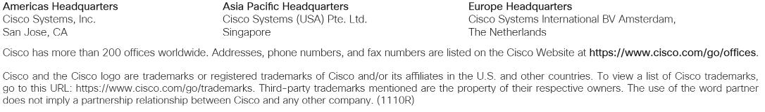
SD-WAN Wizard Deployment Models
Single Hub and Single ISP
● One SD-WAN hub-and-spoke topology
● Total number of SD-WAN VPN tunnels: 4
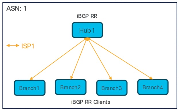
Single Hub and Dual ISPs
● Two SD-WAN hub-and-spoke topologies
● Total number of SD-WAN VPN tunnels: 8
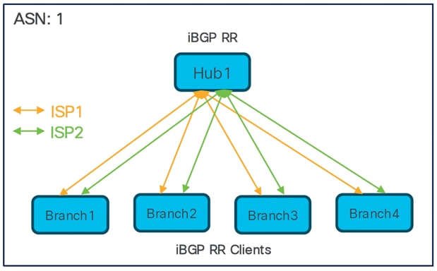
Dual Hubs and Single ISP
● Single SD-WAN hub-and-spoke topology
● Total number of SD-WAN VPN tunnels: 8
Dual Hubs and Dual ISPs
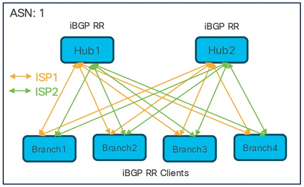
● Two SD-WAN hub-and-spoke topologies
● Total number of SD-WAN VPN tunnels: 16
Dual Hubs in Different Regions and Single ISP
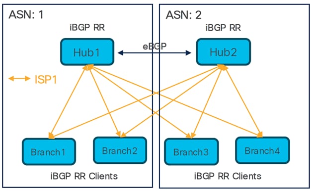
● Two SD-WAN hub-and-spoke topologies
● eBGP peering between hubs
● Total number of SD-WAN VPN tunnels: 8
Dual Hubs in Different regions and Dual ISPs
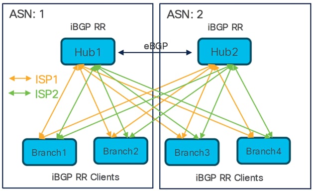
● Four SD-WAN hub-and-spoke topologies
● eBGP peering between hubs
Total number of SD-WAN VPN tunnels: 16
Deploy Dual Hubs and Dual ISPs SD-WAN Overlay Network Using SD-WAN Wizard
Prerequisites for Using SD-WAN Wizard
● Management Center must be Version 7.6.0 and later.
● Hub devices must be Version 7.6.0 and later.
● Spoke devices must be Version 7.3.0 and later.
● Management Center Essentials (formerly Base) license must allow export-controlled functionality.
● You must be an Admin user.
Guidelines for Using SD-WAN Wizard
Guidelines
● When you configure the DVTIs of two hubs, ensure that they have the same IPsec tunnel mode (IPv4 or IPv6).
● If hubs are geographically separated with distinct protected networks, configure a point-to-point route-based VPN topology between them to enable direct communication between these networks (Devices > Site-to-site > Add > Route-Based VPN).
● Choose Routed as the Interface Type when you create security zones or interface groups.
● Use the spoke security zone to configure an access control policy that allows tunnel traffic to and from the spokes.
● If a device has only IPv6 address configurations, you must configure the BGP router ID with a loopback or physical interface that has an IPv4 address (Device > Device Management > Routing > General Settings > BGP).
● Configure unique local IKE identity for all tunnels across all your SD-WAN VPN topologies.
Key Considerations
● You can configure a maximum of two hubs in an SD-WAN topology using the SD-WAN wizard.
● For each spoke, you can use only one WAN interface per topology.
A spoke with a second WAN interface cannot be added to an existing SD-WAN topology if it already exists with the first WAN interface. However, for dual-ISP setups, you can configure a second SD-WAN topology with the second WAN interface.
● Secure Firewall supports a maximum of 1024 virtual tunnel interfaces.
● Secure Firewall supports a maximum of 500 BGP peers per device.
● SD-WAN wizard does not support these features:
◦ IKEv1
◦ Cluster devices are not supported on the hub and spoke because VTI is not supported on cluster devices.
◦ Extranet hubs and spokes such as ASA, Cisco IOS, Cisco Viptela, Umbrella, Meraki, or vendor devices.
Network Topology
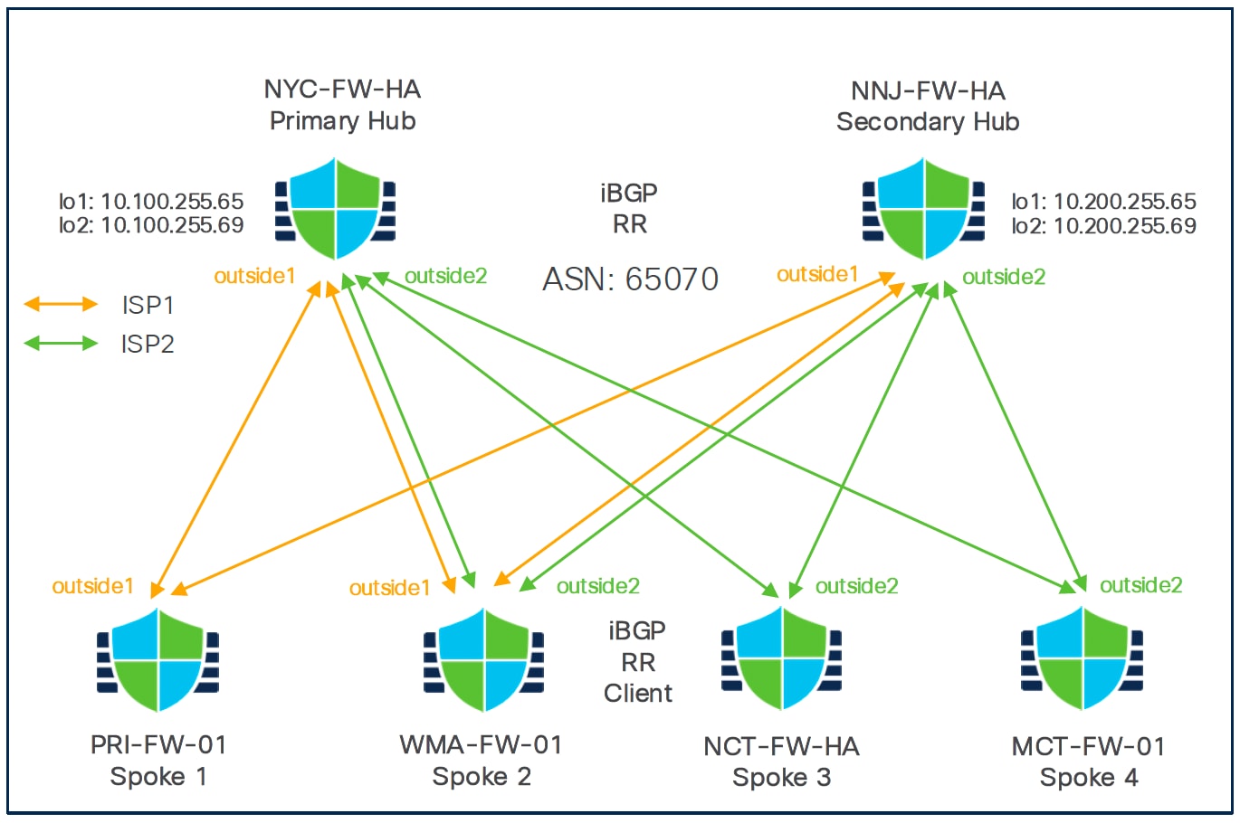
In this dual ISP topology, the hubs and the spokes are in a single region, with AS number (ASN) as 65070. The hubs and spokes use Internal Border Gateway Protocol (iBGP) as the routing protocol to exchange routing information.
To configure VPN tunnels between the hubs and spokes of this topology, you must create two SD-WAN topologies using the SD-WAN wizard:
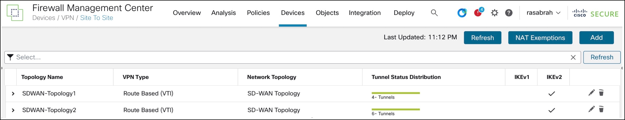
Table 1. SD-WAN Topology 1
| Parameter |
Value |
| Primary Hub |
NYC |
| Secondary Hub |
NNJ |
| Spokes |
Branch1 (PRI) , Branch2 (WMA) |
| ASN |
65070 |
| BGP Community |
1000 |
| VPN Interface |
outside1 (ISP1) |
| Number of Tunnels |
4 |
Table 2. SD-WAN Topology 2
| Parameter |
Value |
| Primary Hub |
NNJ |
| Secondary Hub |
NYC |
| Spokes |
Branch2 (WMA), Branch3 (NCT), Branch4 (MCT) |
| ASN |
65070 |
| BGP Community |
1000 |
| VPN Interface |
outside2 (ISP2) |
| Number of Tunnels |
6 |
Note: Two SD-WAN VPN tunnels are established to each hub from the outside2 interface of each branch. Hence, the number of SD-WAN VPN tunnels in SD-WAN Topology 2 is 6.
The total number of VPN tunnels for this dual ISP deployment is 10.
Configure SD-WAN Overlay Using SD-WAN Wizard
You must configure two SD-WAN topologies:
● SDWAN-Topology1 with outside1 as the spoke's VPN interface for ISP1
● SDWAN-Topology 2 with outside2 as the spoke's VPN interface for ISP2
Step 1. Choose Devices > VPN > Site to Site, and click Add.
Step 2. Click the SD-WAN Topology radio button.
Step 3. In the Topology Name field, enter SDWAN-Topology1 as the name for the topology.
Step 4. Click Create.
Step 5. Configure hubs:
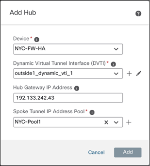
i. Click Add Hub.
ii. From the Device drop-down list, choose a hub. In this example, choose NYC-FW-HA.
iii. Click + next to the Dynamic Virtual Tunnel Interface (DVTI) drop-down list to add a dynamic VTI for the hub.
iv. The Add Virtual Tunnel Interface dialog box is prepopulated with default configurations. However, you must configure the following parameters:
- From the Security Zone drop-down list, choose a security zone. In this example, it is tunnel-zone.
- From the Tunnel Source drop-down list, choose the physical interface that is the source of the dynamic VTI. Choose the IP address of this interface from the adjacent drop-down list. In this example, it is Ethernet1/1.
- From the Borrow IP drop-down list, choose a loopback interface from the drop-down list. The dynamic VTI inherits this IP address. If you do not have a loopback interface, click + to create one. In this example, it is Loopback1.
- Click OK.
v. In the Hub Gateway IP Address field, enter the public IP address of the hub's VPN interface or the tunnel source of the dynamic VTI to which the spokes connect.
Note: This IP address is auto populated if the interface has a static IP address. If hub is behind a NAT device, you must manually configure the post-NAT IP address.
vi. From the Spoke Tunnel IP Address Pool drop-down list, choose an IP address pool or click + to create an address pool.
Note: Ensure that you do not check the Allow Overrides check box when you create an address pool in the Add IP Pool dialog box as each IP address pool must be unique.
When you add spokes, the wizard auto generates spoke tunnel interfaces, and assigns IP addresses to these spoke interfaces from this IP address pool. In this example, it is NYC-Pool1.
vii. Click Add to save the hub configuration.
viii. To add the secondary hub, repeat Step 5a to Step 5g. In this example, it is NNJ-FW-HA.
Step 6. Configure spokes:
a. Click Add Spokes (Bulk Addition).
a. In the Add Bulk Spokes dialog box, configure the following parameters:
i. Choose the spoke devices from the Available Devices list and click Add to move the devices to Selected Devices. In this example, they are PRI-FW-01 and WMA-FW-01.
ii. Use one of the following methods to select the VPN interfaces of the spokes:
iii. Click the Interface Name Pattern radio button and specify a string to match the logical name of the internet or WAN interface of the spokes, for example, outside*, wan*. In our example, the string for the ISP1 interface is outside1.
If the spoke has multiple interfaces with the same pattern, the first interface that matches the pattern is selected for the topology.
Or
Click the Security Zone radio button and choose a security zone with the VPN interfaces of the spokes from the drop-down list, or click + to create a security zone.
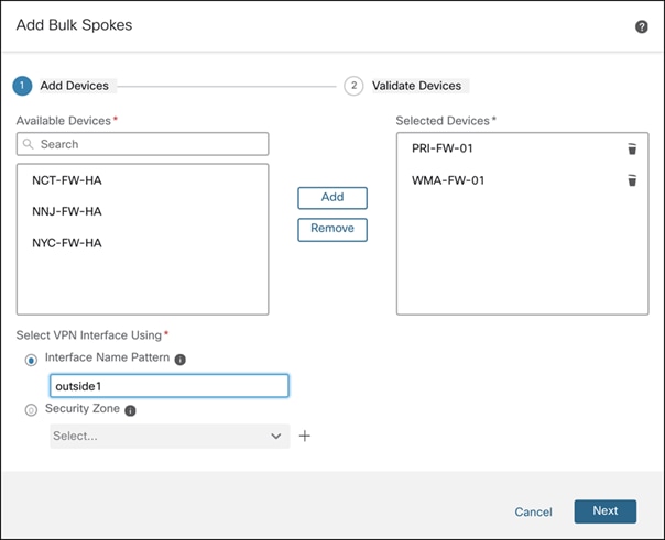
b. Click Next. The wizard validates if the spokes have interfaces with the specified pattern. Only the validated devices are added to the topology.
c. Click Add, and click Next. For each spoke, the wizard automatically selects the hub's public IP address (as defined in Hub Gateway IP Address) as the tunnel destination IP address.
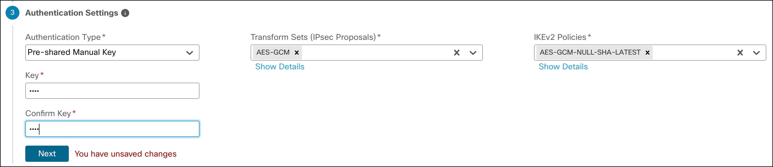
Step 7. Configure Authentication Settings for the devices in the SD-WAN topology:
a. From the Authentication Type drop-down list, choose a manual pre-shared key, an auto-generated pre-shared key, or a certificate for device authentication.
You can use the default settings in this step and proceed to the next step. If required, you can edit the settings later. In this example, we use Pre-shared Manual Key for device authentication.
◦ Pre-shared Manual Key—Specify the pre-shared key for the VPN connection.
◦ Pre-shared Automatic Key—(Default value) The wizard automatically defines the pre-shared key for the VPN connection. Specify the key length in the Pre-shared Key Length field. The range is 1 to 127.
◦ Certificate—When you use certificates as the authentication method, the peers obtain digital certificates from a CA server in your PKI infrastructure, and use them to authenticate each other.
b. From the Transform Sets drop-down list, choose one or more algorithms or use the default value.
c. From the IKEv2 Policies drop-down list, choose one or more algorithms or use the default value.
d. Click Next.
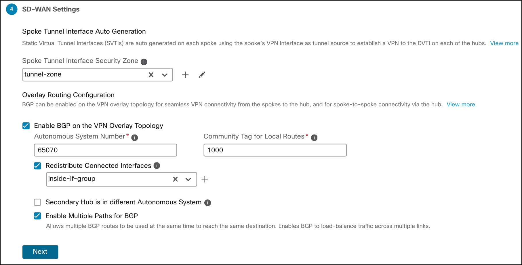
Step 8. Configure SD-WAN Settings:
This step involves the auto generation of spoke tunnel interfaces, and BGP configuration of the overlay network.
a. From the Spoke Tunnel Interface Security Zone drop-down list, choose a security zone or click + to create a security zone to which the wizard automatically adds the spokes' auto-generated Static Virtual Tunnel Interfaces (SVTIs). In this example, the security zone is tunnel-zone.
b. Check the Enable BGP on the VPN Overlay Topology check box to automate BGP configurations such as neighbor configurations between the overlay tunnel interfaces and basic route redistribution from the directly connected LAN interfaces of the hubs and spokes.
c. In the Autonomous System Number field, enter an Autonomous System (AS) number. In this example, the AS number is 65070.
d. In the Community Tag for Local Routes field, enter the BGP community attribute to tag connected and redistributed local routes.
This attribute enables easy route filtering. Note this community string, you must use the same community string for the second SD-WAN VPN topology. In this example, the community string is 1000.
e. Check the Redistribute Connected Interfaces check box and choose an interface group from the drop-down list or click + to create an interface group with connected inside or LAN interfaces for BGP route redistribution in the overlay topology. In this example, the interface group is inside-if-group.
f. Check the Enable Multiple Paths for BGP check box to allow multiple BGP routes to be used at the same time to reach the same destination. This option enables BGP to load-balance traffic across multiple links.
g. Click Next.
h. Click Finish to save and validate the SD-WAN topology.
Step 9. Repeat Step 1 to Step 8 to configure the SDWAN-Topology2 with the VPN interface for ISP2: outside2.
You can view the topology in the Site-to-Site VPN Summary page (Devices > Site to Site VPN). After you deploy the configurations to all the devices, you can see the status of all the tunnels in this page.
Configure Overlay Routing for the SD-WAN Network
While the SD-WAN Wizard automatically redistributes directly connected interfaces, full end-to-end site-to-site communication often requires additional route redistribution, especially if there are other routers or internal networks behind the Threat Defense device.
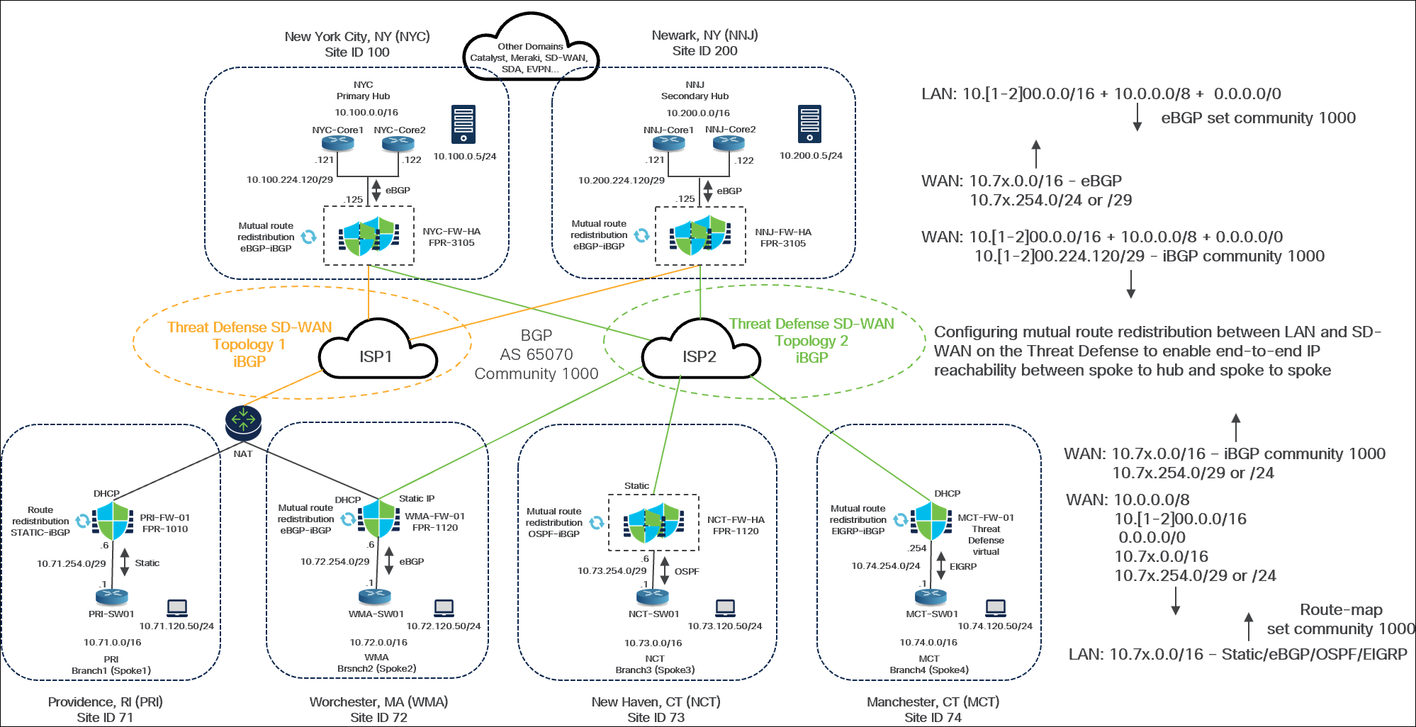
In this example, the topology has these parameters:
Hub Sites
● New York City, NYC: Designated as the Primary Hub. It uses a NYC-FW-HA FPR-3105 firewall in a HA pair.
◦ Use eBGP peering between the Core switches and the Theat Defense device (NYC-FW-HA)
● Newark, NY (NNJ)
◦ Designated as the Secondary Hub. It uses an NNJ-FW-HA FPR-3105 firewall, also in an HA pair.
● Both hubs utilize a pair of Layer 2/Layer 3 core switches ("NYC Core 1 and Core 2") for interconnecting various internal domains.
● DNS servers 10.100.0.5/24 and 10.200.0.5/24 are available at these sites for testing purposes.
Spoke Sites: There are four branch offices, each with a different routing configuration for its LAN:
● Providence, RI (PRI):
◦ Static routing on Threat Defense (PRI-FW-01) for LAN connectivity towards PRI-SW01.
◦ Route redistribution configured between Static routes and iBGP.
● Worchester, MA (WMA):
◦ eBGP peering between Threat Defense (WMA-FW-01) and (WMA-SW01) LAN switch
◦ Mutual route redistribution configured between eBGP and iBGP.
● New Haven, CT (NCT):
◦ OSPF peering between Theat Defense (NCT-FW-HA) and Layer 2/Layer 3 (NCT-SW01) LAN switch
◦ Mutual route redistribution configured between OSPF and iBGP.
● Manchester, CT (MCT):
◦ EIGRP between from Theat Defense (MCT-FW-01) and Layer 2/Layer 3 (MCT-SW01) LAN switch
◦ Mutual route redistribution configured between EIGRP and iBGP.
Note: We strongly recommend using route maps to control your route redistribution. This helps to avoid potential routing loops.
Hub-Side (New York City) Route Advertisement (eBGP)
In this example, for the New Your City Hub, three primary routes are advertised through eBGP:
● 10.100.0.0/16
● A summarized or aggregated route of 10.0.0.0/8
The Core is set to advertise these routes with a BGP community of 1000. If the BGP community is not set correctly, these routes will not be redistributed into the overlay. A BGP community of 1000 is set for these routes.
Route Redistribution from WAN to LAN (at Hubs)
On the Threat Defense devices at the Hub sites, a route map is configured to control the advertisement of routes from the SD-WAN overlay (WAN) back to the LAN side:
● This route map specifically controls the advertisement of 10.7x.x.x/16 networks, where ‘x’ corresponds to the branch locations (for example, 71 for PRI, 72 for WMA, 73 for NCT, 74 for MCT).
● Only specific WAN interface routes, 10.7x.254.0/24 or /29, are advertised. This is because these represent directly connected interfaces, which are necessary for the hub to correctly install routes.
● If these specific routes are not advertised, the summary routes that we advertised from the branches will not be installed. This is necessary to facilitate recursive routing lookup, ensuring the correct next-hop information is correctly installed in the routing table.
Threat Defense Advertisement into the SD-WAN Overlay
● Threat Defense devices in Hub advertise directly connected segments (10.100.224.120/29, 10.200.224.120/29) with an iBGP community of 1000.
● Routes received from the LAN side (using eBGP redistribution) that already have the BGP community set (for example, 1000) are also advertised into the overlay.
Receiving Side (Hubs) Route Acceptance
● On the receiving side (hubs), a route map is configured on the Threat Defense devices to only accept routes that have the BGP community set to 1000.
Need for Route Redistribution
The LAN-side networks (for example, at the branch/spoke sites such as PRI, WMA, NCT, MCT, and behind the hub sites NYC, NNJ) are not directly connected to the Threat Defense devices. Therefore, they cannot communicate directly with one another.
Instead, these LAN networks are connected through other routing protocols or static routes configured on separate Layer 2/Layer 3 switches or routers behind the Threat Defense devices.
● PRI uses static routing
● WMA uses eBGP
● NCT uses OSPF
● MCT uses EIGRP
The hub sites (NYC, NNJ) also have core switches or routers behind them that use eBGP to advertise their internal networks.
For devices at one branch to communicate with devices at another branch or at the hub, all relevant LAN-side routes must be advertised into the SD-WAN BGP overlay running BGP, and the overlay BGP routes must be advertised back into the LAN routing domains.
Although the SD-WAN wizard simplifies deployment by automatically configuring BGP on the overlay and redistributing directly connected (inside or LAN-facing) interfaces, this is often insufficient in environments where LAN-side networks are not directly connected to the Threat Defense devices and rely on other routing protocols or static routes. In these cases, you must manually configure mutual route redistribution between the LAN-side routing protocols (such as Static, eBGP, OSPF, or EIGRP) and the SD-WAN BGP overlay to ensure full end-to-end IP reachability between spoke and hub sites.
View BGP Peering in Hub
Step 1. Choose Devices > Device Management.
Step 2. Click NNJ-FW-HA from the device listing page.
Step 3. Click the Summary tab.
Step 4. In the General area, click CLI and execute the following command to view the route advertised to the LAN neighbor:
> show bgp summary
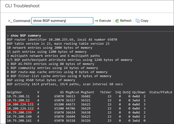
The highlighted IP addresses are the two eBGP peering established between the Threat Defense devices at the hub and their respective LAN-side core switches.
View Advertised Routes to Neighbors
To view BGP routes that the Threat Defense is advertising to its specific eBGP neighbor:
Step 1. Choose Devices > Device Management.
Step 2. Click NNJ-FW-HA from the device listing page.
Step 3. Click the Summary tab.
Step 4. In the General area, click CLI and execute the following command:
> show bgp neighbors 10.200.224.121 advertised-routes
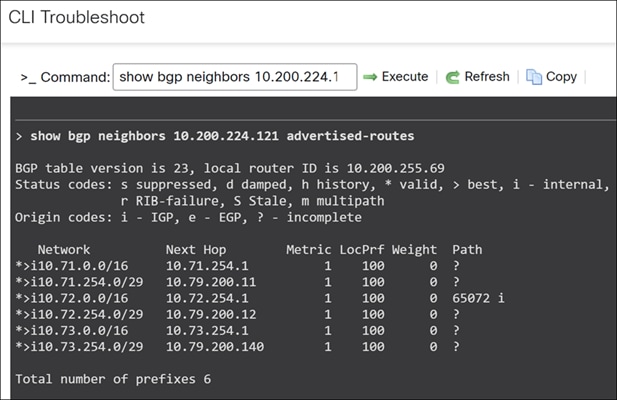
Step 5. To view the routes received by the Threat Defense device from the LAN side:
> show bgp neighbors 10.200.224.121 routes
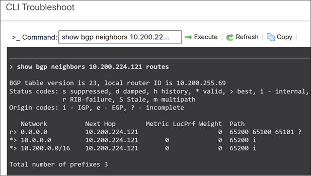
The LAN side (core switches) will advertise routes including a default route (0.0.0.0/0), a summary route of 10.0.0.0, and specific routes such as 10.200.0.0/16 for the New Jersey location.
NNJ-FW-HA (Hub): Configure BGP for SD-WAN Overlay
Step 1. Choose Devices > Device Management.
Step 2. Click NNJ-FW-HA from the device listing page.
Step 3. Click the Routing tab.
Step 4. Under General Settings, click BGP.
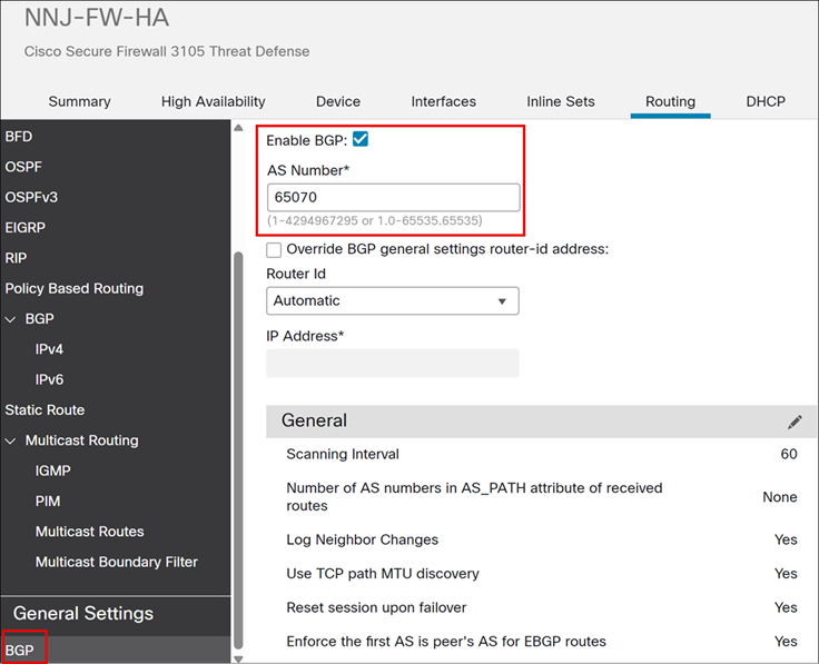
Step 5. Check the Enable BGP check box to enable the BGP routing process.
Step 6. In the AS Number field, enter the autonomous system (AS) number for the BGP process.
In this example, a private AS number of 65070 is used for the SD-WAN overlay.
Step 7. Choose BGP > IPv4.
Step 8. Check the Enable BGP check box to enable the BGP routing process.
Step 9. Click Neighbor.
Step 10. Click Add to define BGP neighbors and neighbor settings.
In this example, two neighbors are configured, 10.200.224.121(NNJ-Core1) and 10.200.224.122 (NNJ-Core2), which represents the core switches.
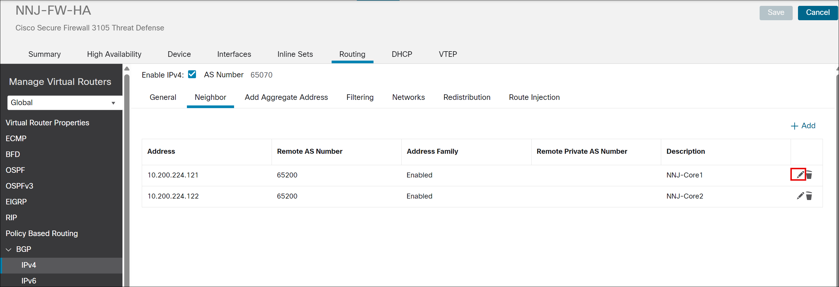
Step 11. Click Edit icon next to one of the existing neighbors to see the configuration details.
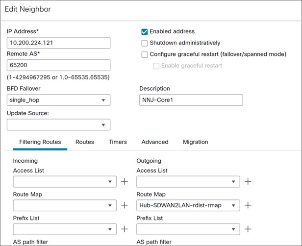
The Route Map can be used to manage route redistribution in both directions, inbound and outbound. In our example, specifically for BGP, we are using an outbound route map (from SD-WAN to LAN) and not employing any inbound route map (from LAN to SD-WAN).
Configure IPv4 Prefix List for Hub
Step 1. Choose Objects > Object Management.
Step 2. Choose Prefix List > IPv4 Prefix List.
Step 3. Click Add IPv4 Prefix List.
Step 4. In the Name field, enter All-branch-inside-networks.
Step 5. Click Add.
The Add Prefix List Entry dialog box is displayed. You can configure the following:
- Action: Allow
- Sequence No: 10
- IP Address: 10.64.0.0/12. The IP address represents a summarized range of spoke-side networks, specifically PRI (71), WMA(72), NCT(73), and MCT(74). It allows route matching based on defined subnet mask criteria, such as a minimum mask length of /16 and a maximum mask length of /29.
- Minimum prefix length: 16
- Maximum Prefix Length: 29
Step 6. Click Add.
Step 7. Click Save.
Create Community List for Hub
Step 1. Choose Objects > Object Management.
Step 2. Expand Community List and click Community.
Step 3. Click Add Community List.
Step 4. In the Name field, enter a name. In this example, we use SDWAN-BGP-community.
Step 5. Click Add.
The Add Community List Entry dialog box.
Step 6. Select the Standard radio button to indicate the community rule type.
Step 7. From the Action drop-down list, select the Allow option to indicate redistribution access.
Step 8. In the Communities field, specify a community number. In this example, we enter 1000.
Step 9. Click Add.
Step 10. Click Save.
Add a Route Map Object for Hub
Step 1. Choose Objects > Object Management.
Step 2. Click Route Map.
Step 3. Click Add Route Map.
Step 4. In the Name field, enter Hub-SDWAN2LAN-rdist-rmap.
Step 5. Click Add.
Step 6. In the Sequence No. field, enter a number. In this example, we enter 10.
Step 7. Select the Allow action from the Redistribution drop-down list, to indicate the redistribution access.
Step 8. Click IPv4.
i. Click the Address tab.
ii. Choose Prefix list for matching from the drop-downlist and then enter or select the Prefix list objects you want to use for matching. In this example, we choose All-branch-inside-networks.
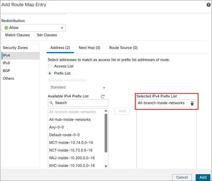
iii. Click Add.
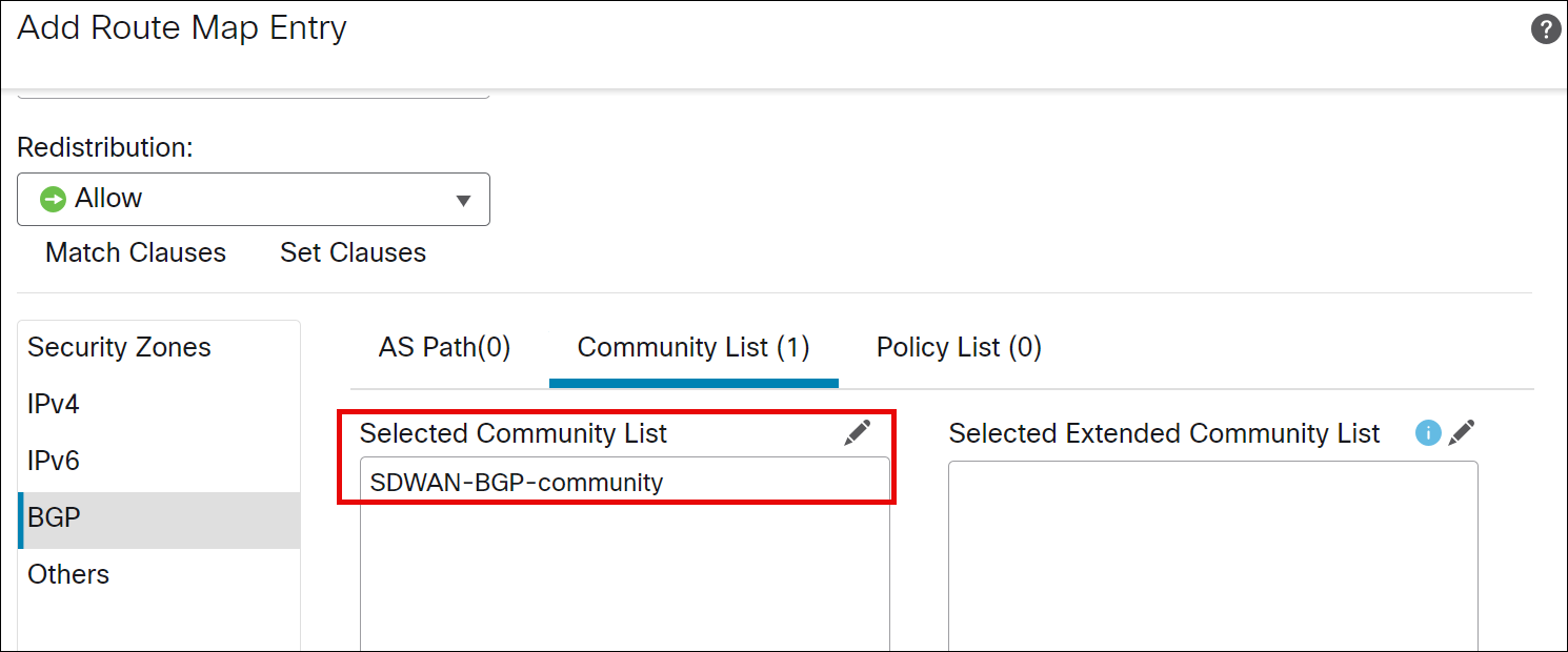
Step 9. Click BGP.
Step 10. Click the Community List tab.
Step 11. Click edit and select SDWAN-BGP-community community list.
Step 12. Click OK.
Step 13. Click Add.
Step 14. Click Save.
PRI Branch (Spoke 1): Configure Static and iBGP Mutual Route Redistribution
PRI Branch (Spoke 1) is configured to use static routing on its LAN side.
Configure IPv4 Prefix List for PRI (Spoke)
Step 1. Choose Objects > Object Management.
Step 2. Choose Prefix List > IPv4 Prefix List.
Step 3. Click Add IPv4 Prefix List.
Step 4. In the Name field, enter PRI-inside-10.71.0.0-16.
Step 5. Click Add.
The Add Prefix List Entry dialog box is displayed. You can configure the following:
- Action: Allow
- Sequence No: 10
- IP Address: 10.64.0.0/16
Step 6. Click Add.
Step 7. Click Save.
Add a Route Map Object for PRI (Spoke)
Step 1. Choose Objects > Object Management.
Step 2. Click Route Map.
Step 3. Click Add Route Map.
Step 4. In the Name field, enter Static2iBGP-rdist-rmap.
Step 5. Click Add.
Step 6. In the Sequence No. field, enter a number. In this example, we enter 10.
Step 7. Select the Allow action from the Redistribution drop-down list, to indicate the redistribution access.
Step 8. Click IPv4.
Step 9. Click the Address tab.
Step 10. Choose Prefix list for matching from the drop-downlist and then enter or select the Prefix list objects you want to use for matching. In this example, we choose PRI-inside-10.71.0.0-16.
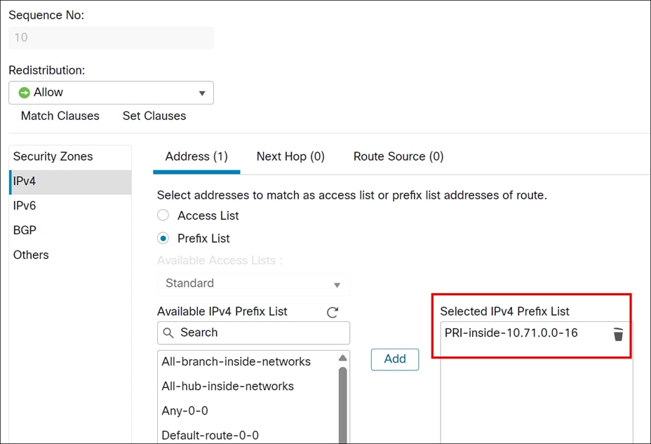
Step 11. Click Add.
Step 12. Click Save.
Configure Static Route Redistribution for Spoke (PRI-FW-01)
Step 1. Choose Devices > Device Management.
Step 2. Click PRI-FW-01 from the device listing page.
Step 3. Click the Routing tab.
Step 4. Click Static Route.
A static route from the firewall points back to the LAN side.
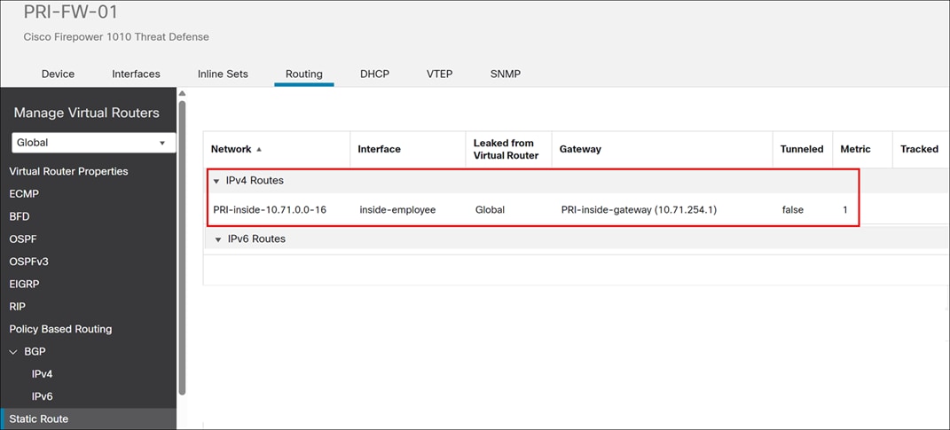
The static route must be redistributed into BGP.
Step 5. Under General Settings, click BGP.
Step 6. Check the Enable BGP check box to enable the BGP routing process.
Step 7. In the AS Number field, enter the autonomous system number and click Save.
In this example, the AS number is 65070.
Step 8. Choose BGP > IPv4.
Step 9. Check the Enable IPv4 check box.
Step 10. Click the Redistribution tab. Redistribution settings allow you to define the conditions for redistributing routes from another routing domain into BGP.
Step 11. Click Add.
Step 12. In the Add Redistribution dialog box, configure these parameters:
i. From the Source Protocol drop-down list, choose the protocol from which you want to redistribute routes into the BGP domain. In this example, choose Static.
ii. In the Metric field, enter a metric for the redistributed route. In this example, the value is 1.
iii. In the Route Map drop-down list, enter or choose a route map that should be examined to filter the networks to be redistributed. If not specified, all networks are redistributed. The Static2iBGP-rdist-map is selected. This ensures that only desired routes are advertised and that they are tagged with the correct community for proper routing within the SD-WAN overlay.
iv. Click OK.
Step 13. Click Save.
WMA Branch (Spoke 2): Configure eBGP and iBGP Mutual Route Redistribution
You do not have to manually configure route redistribution between the LAN side (eBGP) and the SD-WAN overlay (iBGP) because WMA uses eBGP. The Threat Defense devices automatically redistribute routes between eBGP and iBGP. This simplifies the configuration process for branches using eBGP.
NCT Branch (Spoke 3): Configure OSPF and iBGP Mutual Route Redistribution
Configure IPv4 Prefix List for NCT (Spoke)
Step 1. Choose Objects > Object Management.
Step 2. Choose Prefix List > IPv4 Prefix List.
Step 3. Click Add IPv4 Prefix List.
Step 4. In the Name field, enter NCT-inside-10.73.0.0-16.
Step 5. Click Add.
The Add Prefix List Entry dialog box is displayed. You can configure the following:
- Action: Allow
- Sequence No: 10
- IP Address: 10.73.0.0/16
Step 6. Click Add.
Step 7. Click Save.
Add a Route Map Object for NCT (Spoke)
Configure a route map from OSPF to iBGP.
Step 1. Choose Objects > Object Management.
Step 2. Click Route Map.
Step 3. Click Add Route Map.
Step 4. In the Name field, enter OSPF2iBGP-rdist-rmap.
Step 5. Click Add.
Step 6. In the Sequence No. field, enter a number. In this example, we enter 10.
Step 7. Choose the Allow action from the Redistribution drop-down list, to indicate the redistribution access.
Step 8. Click IPv4.
i. Click the Address tab.
ii. Choose Prefix list for matching from the drop-downlist and then enter or select the Prefix list objects you want to use for matching. In this example, we choose NCT-inside-10.73.0.0-16.
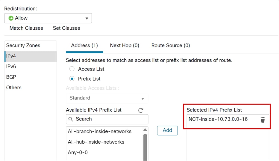
iii. Click Add.
Step 9. Click Save.
Add a Route Map Object for NCT (Spoke)
Configure a route map from SD-WAN to LAN side of the branch.
Step 1. Choose Objects > Object Management.
Step 2. Click Route Map.
Step 3. Click Add Route Map.
Step 4. In the Name field, enter Branch-SDWAN2LAN-rdist-map.
Step 5. Click Add.
Step 6. In the Sequence No. field, enter a number. In this example, we enter 10.
Step 7. Select the Allow action from the Redistribution drop-down list, to indicate the redistribution access.
Step 8. Click Add.
Step 9. Click Save.
Configure OSPF and iBGP Mutual Route Redistribution for Spoke (NCT-FW-HA)
The configuration for NCT, a spoke site in the topology, integrates its LAN-side OSPF routing with the SD-WAN overlay's BGP routing to ensure end-to-end IP reachability across the network.
Step 1. Choose Devices > Device Management.
Step 2. Click NCT-FW-HA from the device listing page.
Step 3. Click the Routing tab.
Step 4. Under General Settings, click BGP.
Step 5. Check the Enable BGP check box to enable the BGP routing process.
Step 6. In the AS Number field, enter the autonomous system number and click Save. In this example, the AS number is 65070.
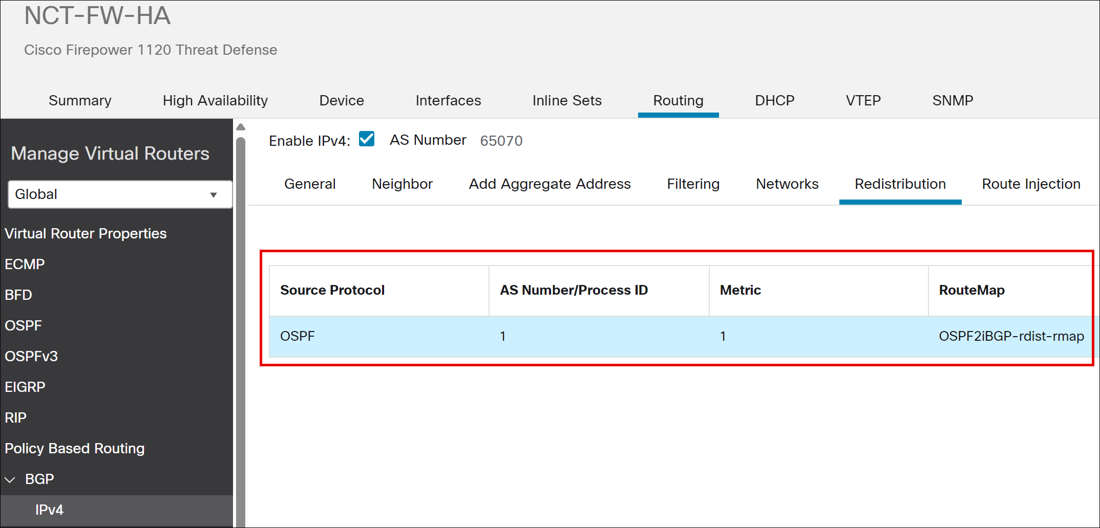
Step 7. Choose BGP > IPv4.
i. Check the Enable IPv4 check box.
ii. Click the Redistribution tab. Redistribution settings allow you to define the conditions for redistributing routes from another routing domain into BGP.
iii. Click Add.
iv. In the Add Redistribution dialog box, configure these parameters:
v. From the Source Protocol drop-down list, choose the protocol from which you want to redistribute routes into the BGP domain. In this example, choose OSPF.
vi. In the Metric field, enter a metric for the redistributed route. In this example, the value is 1.
vii. In the Route Map drop-down list, enter or choose a route map that should be examined to filter the networks to be redistributed. If not specified, all networks are redistributed. The OSPF2iBGP-rdist-map is selected. This ensures that only desired routes are advertised and that they are tagged with the correct community for proper routing within the SD-WAN overlay.
i. Click OK.
Step 8. Click Save.
Step 9. Click OSPF.
Step 10. We are redistributing routes learned through BGP (from the SD-WAN overlay) back into the OSPF domain on the LAN side of the NCT device.
Step 11. Click Redistribution.
Step 12. Click Add.
Step 13. In the Add Redistribution dialog box, configure these parameters:
i. From the OSPF Process drop-down list, choose the process ID as 1. For a device using virtual routing, this drop-down list displays the unique process IDs generated for the selected virtual router.
ii. From the Route Type drop-down list, choose BGP. This redistributes routes from the BGP routing process.
iii. In the AS Number field, enter the AS number.
iv. (Optional) Check the Use Subnets check box.
v. Check the Use Subnets check box.
vi. In the Metric Value field: Metric value for the routes being distributed. In this example, the value 1.
vii. For the Metric Type field, in OSPF, metric types 1 and 2 determine how external routes (those redistributed from other routing protocols) are advertised within the OSPF domain. Type 1 metrics add the internal OSPF cost to reach the Autonomous System Boundary Router (ASBR) to the external cost, providing a more accurate end-to-end path cost. Type 2 metrics only use the external cost, ignoring the internal cost to the ASBR. In this example, we chose metric type 1.
viii. From the RouteMap drop-down list, enter or choose a route map. It checks for filtering the importing of routes from the source routing protocol to the current routing protocol. If this parameter is not specified, all routes are redistributed. Choose Branch-SDWAN2LAN-rdist-map.
ix. Click OK.
Step 14. Click Save.
MCT Branch (Spoke 4): Configure EIGRP and iBGP Mutual Redistribution
Add a Route Map Object for MCT (Spoke)
Configure a route map from SD-WAN to LAN side of the branch.
Step 1. Choose Objects > Object Management.
Step 2. Click Route Map.
Step 3. Click Add Route Map.
Step 4. In the Name field, enter EIGRP2iBGP-rdist-rmap.
Step 5. Click Add.
Step 6. In the Sequence No. field, enter a number. In this example, we enter 10.
Step 7. Select the Allow action from the Redistribution drop-down list, to indicate the redistribution access.
Step 8. Click IPv4.
i. Click the Address tab.
ii. Choose Prefix list for matching from the drop-downlist and then enter or select the Prefix list objects you want to use for matching. In this example, we choose MCT-inside-10.74.0.0-16.
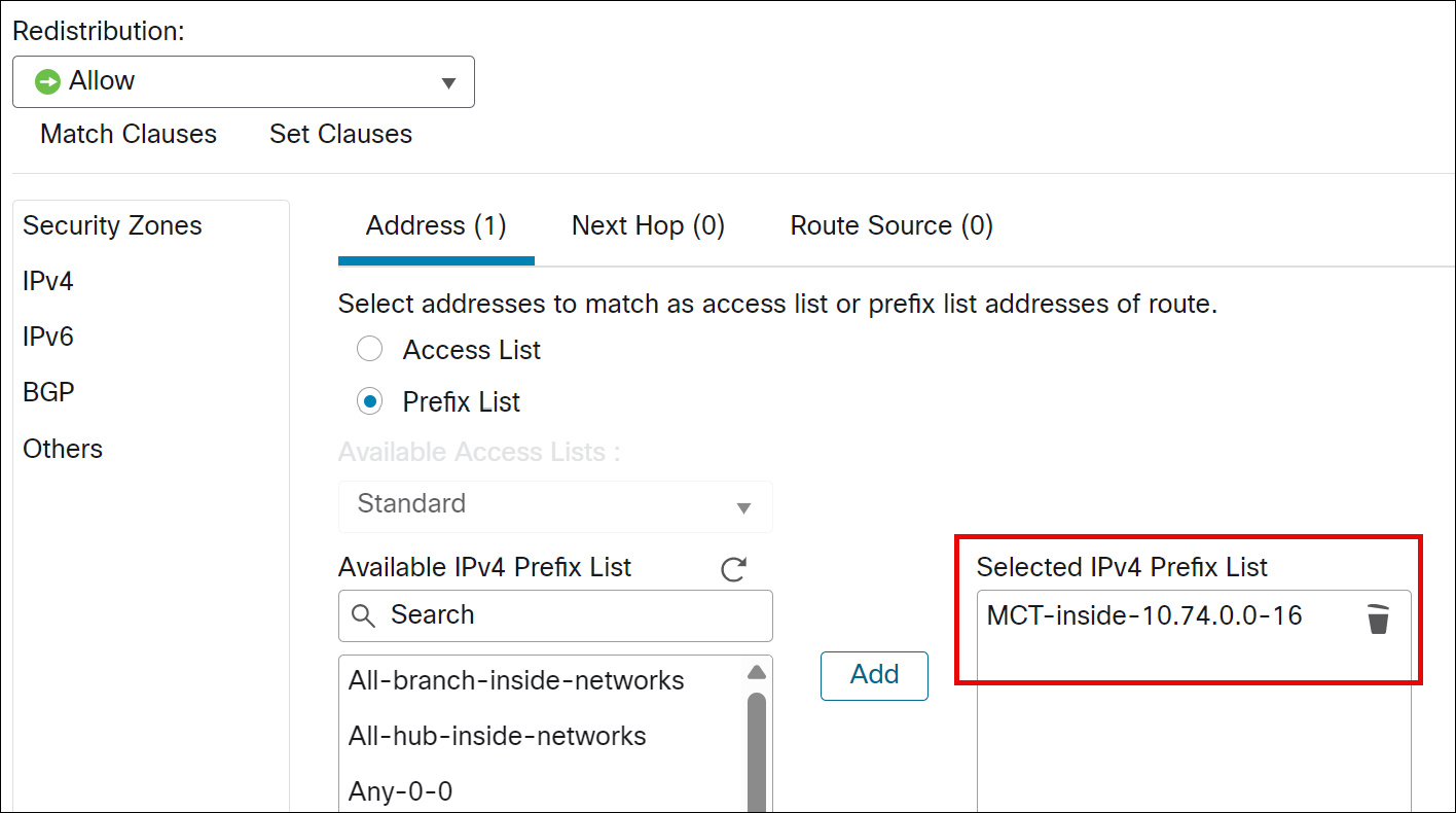
iii. Click Add.
Step 9. Click Save.
Configure EIGRP and iBGP Mutual Route Redistribution for Spoke (MCT-FW-01)
The configuration for MCT Branch (Spoke 4), a spoke site in the topology, integrates its LAN-side EIGRP routing with the SD-WAN overlay's iBGP routing to ensure end-to-end IP reachability across the network.
Step 1. Choose Devices > Device Management.
Step 2. Click MCT-FW-01 from the device listing page.
Step 3. Click the Routing tab.
Step 4. Under General Settings, click BGP.
Step 5. Check the Enable BGP check box to enable the BGP routing process.
Step 6. In the AS Number field, enter the autonomous system number and click Save.
In this example, 65070.
Step 7. Click Save.
Step 8. Choose BGP > IPv4.
Step 9. Check the Enable IPv4 check box.
Step 10. Click the Redistribution tab. Redistribution settings allow you to define the conditions for redistributing routes from another routing domain into BGP.
Step 11. Click Add and update the Add Redistribution dialog:
i. From the Source Protocol drop-down list, choose the protocol from which you want to redistribute routes into the BGP domain. In this example, choose EIGRP.
ii. In the AS Number field, enter the AS number. The AS Number here refers to the EIGRP AS Number (not BGP) and must match the configured EIGRP AS number. In this example, the EIGRP AS number is 74.
iii. For the Metric Type field, enter a metric for the redistributed route. In this example, the value is 1.
iv. From the RouteMap drop-down list, enter or choose a route map that should be examined to filter the networks to be redistributed. If not specified, all networks are redistributed. The EIGRP2iBGP-rdist-map is selected. This ensures that only desired routes are advertised and that they are tagged with the correct community for proper routing within the SD-WAN overlay.
v. Click OK.
Step 12. Click Save.
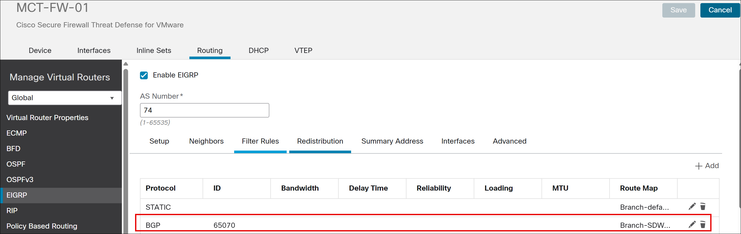
Step 13. Click EIGRP. We are redistributing routes learned through BGP (from the SD-WAN overlay) back into the EIGRP domain on the LAN side of the MCT device.
i. Check the Enable EIGRP check box.
ii. In the AS Number field, specify 74.
iii. From the Available Networks list, choose the MCT-inside-if-subnet network. (Create a network object and assign the value 10.74.254.0/24).
iv. Click Redistribution.
v. In the Add Redistribution dialog box, from the Protocol drop-down, choose the source protocol as BGP from which the routes are being redistributed:
vi. In the Process ID field, enter the process ID 65070.
vii. From the RouteMap drop-down list, enter or choose a route map. In this example, choose route map as Branch-SDWAN2LAN-rdist-rmap.
viii. Click OK.
Step 14. Click Save.
Deploy Configuration to Devices
Step 1. In the Management Center menu bar, click Deploy.
Step 2. Check Deploy All to deploy configuration changes to all devices.
Verify Routing Table on NNJ-FW-HA (Hub)
Step 1. Choose Devices > Device Management.
Step 2. Click NNJ-FW-HA from the device listing page.
Step 3. Click the Device tab.
Step 4. In the General area, click CLI and execute the following:
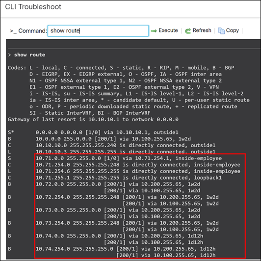
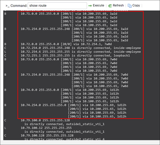
> show route
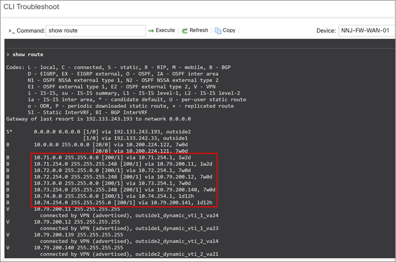
The individual subnets 10.71.0.0, 10.72.0.0, 10.73.0.0, and 10.74.0.0 correspond to the remote branches: PRI, WMA, NCT, and MCT respectively.
Verify Routing Table on MCT-FW-01 Device
To view the complete end-to-end reachability, we will examine the routing table on the MCT spoke device:
Step 1. Choose Devices > Device Management.
Step 2. Click MCT-FW-01 from the device listing page.
Step 3. Click the Device tab.
Step 4. In the General area, click CLI and execute the following:
> show route
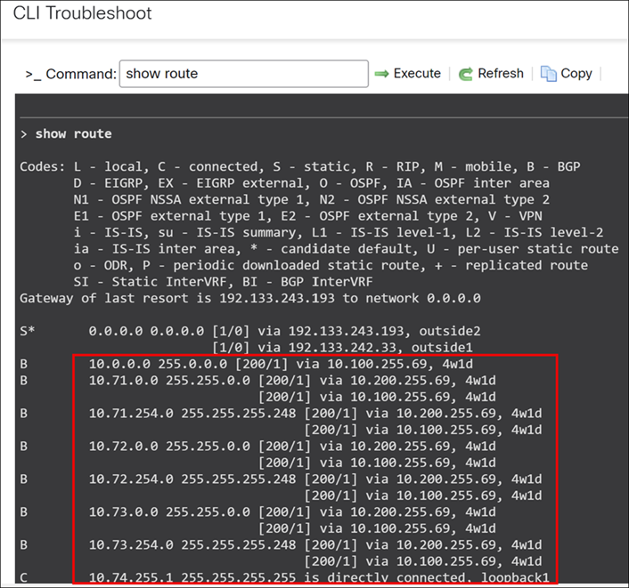
Here, 10.0.0.0 255.0.0.0 represents the aggregate route advertised from the LAN side of the hub sites (New York City and New Jersey).
The individual subnets 10.71.0.0, 10.72.0.0, and 10.73.0.0 correspond to the remote branches: PRI, WMA, and NCT respectively.
Scroll down to see the details of LAN subnets from the hub sites.
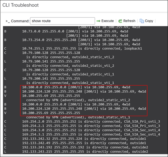
The specific LAN subnets from the hub sites are 10.100.0.0/16 for New York (NYC) and 10.200.0.0/16 for New Jersey (NNJ).
A complete routing table is essential for achieving end-to-end reachability across the entire network. This extensive routing information enables seamless communication not only between spokes and hubs but also directly between spoke sites.
Verify Routing Table on NCT-FW-HA Device
Step 1. To view the complete end-to-end reachability, we will examine the routing table on the MCT spoke device:
Step 2. Choose Devices > Device Management.
Step 3. Click NCT-FW-HA from the device listing page.
Step 4. Click the Device tab.
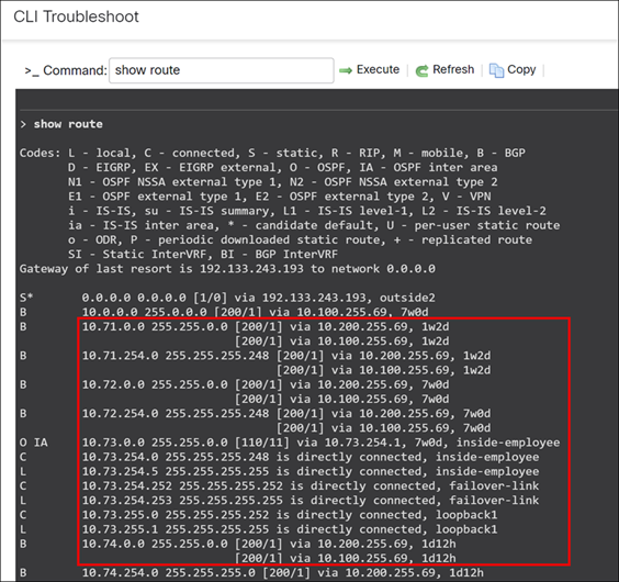
Step 5. In the General area, click CLI and execute the following:
> show route
Verify Routing Table on PRI-FW-01 Device
To view the complete end-to-end reachability, we will examine the routing table on the MCT spoke device:
Step 1. Choose Devices > Device Management.
Step 2. Click PRI-FW-01 from the device listing page.
Step 3. Click the Device tab.
Step 4. In the General area, click CLI and execute the following:
> show route
Verify Routing Table on WMA-FW-01 Device
To view the complete end-to-end reachability, we will examine the routing table on the MCT spoke device:
Step 1. Choose Devices > Device Management.
Step 2. Click WMA-FW-01 from the device listing page.
Step 3. Click the Device tab.
Step 4. In the General area, click CLI and execute the following:
> show route
For more details on SD-WAN design and additional use cases, see Cisco Secure Firewall Threat Defense SD-WAN Design and Deployment Guide.