Cisco Optical Network Controller Configuration Guide, Releases 26.x.x

PDF

Cisco Optical Network Controller Configuration Guide, Releases 26.x.x

Cisco Optical Network Controller nodes

Want to summarize with AI?

Log in

This section explains Cisco Optical Network Controller nodes, including node types, node details, geographic location values, and node state behavior. Use it to understand node information before onboarding or managing nodes.


Cisco Optical Network Controller nodes is a Cisco Optical Network Controller capability that

  • supports the related optical network management workflow,

  • provides context for configuration, monitoring, or troubleshooting tasks, and

  • helps operators understand how the feature behaves before they use it.

Cisco Optical Network Controller nodes details

A node refers to a device in the network. You can add a single node or a set of nodes in the form of a batch at any given point in time.

Use the Nodes screen to view the details of each node. The Nodes table displays the following details for each node:

  • Node Name: The name of the node. The node name provided by you must match the original node name used in Cisco Optical Site Manager. In case of any mismatch or discrepancy issues, user given name is configured on Cisco Optical Site Manager.

  • Product Type: The type of product the node belongs to. For example: Cisco Optical Site Manager.

  • IP: Port (NETCONF): The IP address of each node along with the port number.

  • Site Name: The location of the site that each node belongs to. For example: ROADM_Site_Bengaluru_33

  • Geo Location: The Geo location of each node in terms of the latitude and longitude values based on where exactly the node is situated in the world at any given time.

  • Status: The status of each node within the network to know whether it is active or disconnected.

  • Number of Hosting Servers: Define the number of SVO Line Cards present in the COSM NCS 2000 node.

  • Primary Hosting Server: Displays the active SVO line card hyperlink. Click the hyperlink to open the COSM admin plane for the hosting server.

  • Secondary Hosting Server: Displays the standby SVO line card hyperlink. Click the hyperlink to open the COSM admin plane for the hosting server.

  • Up Time: Displays the duration the COSM node is active.

  • Host Sync Error: Displays the sync error details.

Hover over the information (i) icon that appears along with each node in this Node Name column to view these additional details of a node:
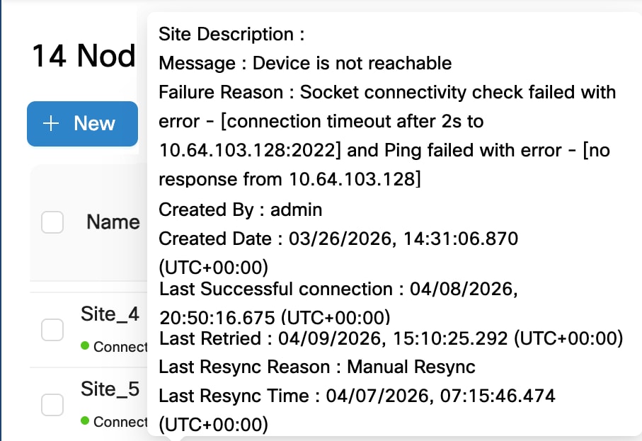
Figure 1. Additional details of a node
  • Site Description: A brief description of the site associated with the node.

  • Message: Displays information about any error conditions related to the node.

  • Failure Reason: Indicates why the node cannot connect or is unreachable. This field is only visible when a node is in Waiting_for_connection state.

    Here are example values for the field:

  • Socket connectivity check failed with error - [dial tcp 10.20.30.40:2020: connect: connection refused] but Ping succeeded

  • Socket connectivity check failed with error - [connection timeout after 2s to 10.20.30.40:22] and Ping failed with error - [no response from 10.20.30.40]

  • Socket connectivity check failed with error - [dial tcp 10.20.30.40:22: connect: no route to host] but Ping succeeded

  • Created by: Displays the user id that added the node.

  • Created Date: Shows the date and time when the node was added.

  • Modified Date: Shows the date and time when the node details were last updated.

  • Last Successful connection: Shows the date and time when the node last connected successfully.

  • Last Retried: Shows the date and time when the last connection attempt was made for this node. This field is only visible when a node is in Waiting_for_connection state.

  • Last Resync Reason: Shows the reason for the most recent resync of the node.

  • Last Resync Time: Shows the date and time when the most recent resync of the node occurred.
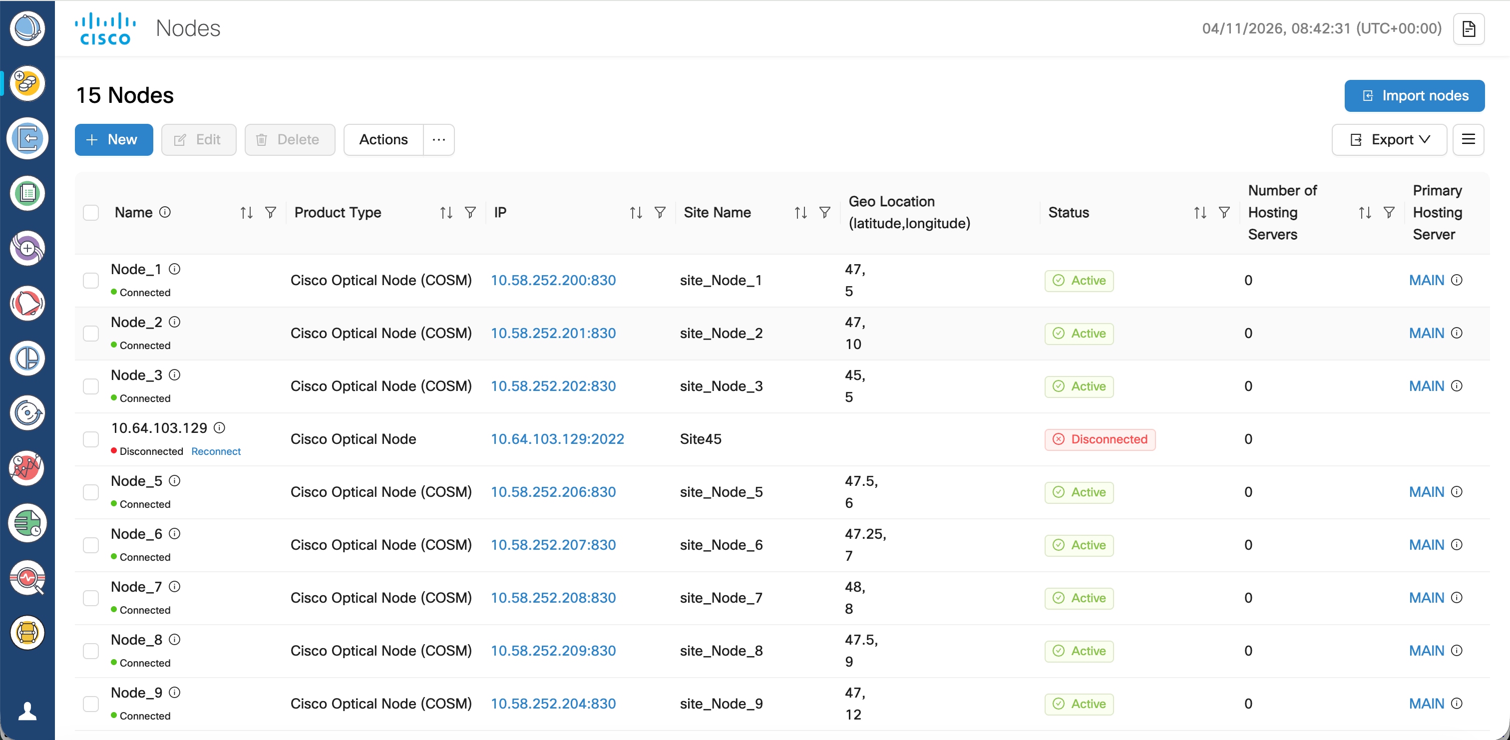
Figure 2. Nodes

From release 26.1.1, the Nodes screen displays the last refreshed information for the primary hosting server. Hover over the i icon to get the latest refreshed information.
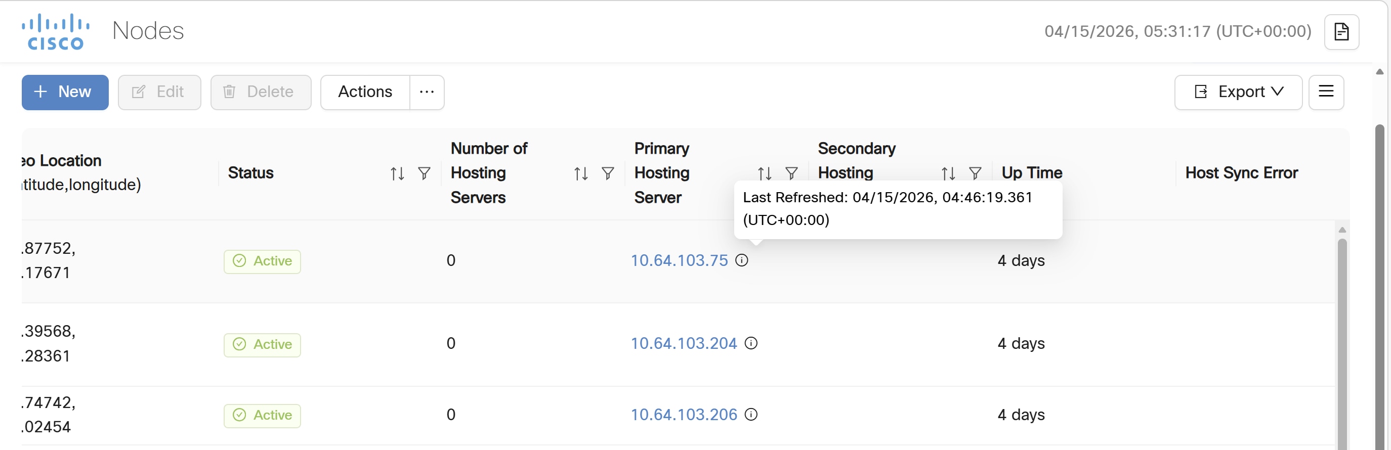
Figure 3. Last Refreshed information

Use the sort or filter options to sort and filter values in the table. You can also cross launch to Cisco Optical Site Manager using the links provided in this table.

Use the Actions button for synchronizing and configuring the network sync along with reconnecting the various nodes present in the network. These are the available options.

  • ReSync: Used for resyncing any selected node in the network.

  • ReSync All: Used for resyncing all the nodes in the network.

  • Reconnect: Used to reconnect any or all the nodes.

  • Configure Network Sync: Used for Daily Network Full Sync. Enable or Disable this functionality.

  • Test Connection: Used for sending pings to the far end node.

  • Resync Host Details: Used for resyncing NCS 2000 node with SVO line cards.

Note
  • Latitude and longitude values can be set in both Cisco Optical Site Manager and Cisco Optical Network Controller. The following scenarios are possible:

  • Geo location is set in both Cisco Optical Site Manager and Cisco Optical Network Controller: Cisco Optical Network Controller Geo location is used.

  • Geo location is set only in Cisco Optical Site Manager: Cisco Optical Site Manager Geo location is used .

  • Geo location is set only in Cisco Optical Network Controller: Cisco Optical Network Controller Geo location is used.

  • Geo location is not set in either Cisco Optical Network Controller or Cisco Optical Site Manager: You will be prompted to add the node in Topology with the edit button.

    For all the cases mentioned above, Cisco Optical Network Controller latitude and longitude value has a higher priority over the Cisco Optical Site Manager latitude and longitude values during the onboarding process. In case the Cisco Optical Network Controller latitude and longitude values are not provided, only then the Cisco Optical Site Manager latitude and longitude values are used.

  • Even if the user updates the Geo location in Cisco Optical Network Controller, it does not get updated in the Cisco Optical Site Manager device.

  • If the Geo location values that are coming from Cisco Optical Site Manager in a pre-filled format has more than four digits, then the length of the Geo location value is truncated to only four digits.

  • Node names are synchronized between Cisco Optical Network Controller and the nodes it manages. During onboarding, node name provided in Cisco Optical Network Controller is pushed to the node if the node has a different name. Changes made on Cisco Optical Site Manager is reverted as Cisco Optical Network Controller pushes the original name to Cisco Optical Site Manager.

    During a onboard and resync operation, Cisco Optical Network Controller pushes the current node name to the node, ensuring consistency even if changes were missed while the device was offline.

Reserved internal IP addresses and subnets

Cisco Optical Network Controller uses specific IP addresses and subnets for its internal network. These ranges are reserved and must not overlap with the IP addresses assigned to any nodes.

Before adding nodes to the Cisco Optical Network Controller, ensure their IP addresses are planned accordingly and do not fall within any of the reserved internal IP ranges in this list.

  • 10.241.x.x/24

  • 10.242.x.x/24

  • 10.243.x.0/24

  • 10.91.0.0/16

  • 10.92.0.0/16

  • 10.93.0.0/16

  • 172.16.0.1/32

Note

Do not use the subnets configured for the control plane for any other purpose.


Add nodes on Cisco Optical Network Controller

Use this procedure to add nodes on Cisco Optical Network Controller in Cisco Optical Network Controller. Complete this task when you need to configure, verify, or manage the related network operation.

Use this task to add a single Cisco Optical Site Manager node.

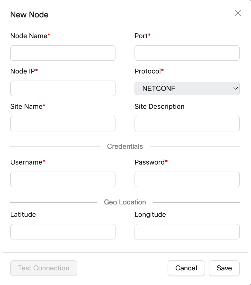
Figure 4. Add New Node

Before you begin

Verify these before addding to Cisco Optical Network Controller:

  • Verify the Cisco Optical Site Manager is reachable from Cisco Optical Network Controller server via DCN.

  • NETCONF port is enabled on the Cisco Optical Site Manager. For more details, see Enable NETCONF over SSH.

  • The COSM1K (NCS 1000 series) nodes must be added using port number 2022.

  • All COSM2K (NCS 2000 series) nodes must be added using port number 830.

  • You must add only fully configured nodes. All passives and patchcords must already be created before you add a node.

Follow these steps to add nodes on Cisco Optical Network Controller:

Procedure

1.

Click Nodes in the left panel.

2.

Click New.

3.

In the New Node dialog box, enter the details necessary connect to the node.

Ensure that you enter valid a username and password of the node to enable Cisco Optical Network Controller to connect to the node. For details about field descriptions, see the Table 1 table.

Note

Use a Cisco Optical Site Manager administrator account to add and manage a Cisco Optical Site Manager node in Cisco Optical Network Controller. This account is required for onboarding and ongoing node operations, including performance monitoring collection, service provisioning and deletion, database backup and restore, and software download and activation. Other Cisco Optical Site Manager user roles are not supported for these operations.

4.

To test connectivity from Cisco Optical Network Controller to a Cisco Optical Site Manager node, perform these steps:

  1. (Optional) Click Test Connection to test the connectivity to the node.

    Note

    The Test Connection button is enabled only if the Node Name, Port and Node IP fields are filled.

    The Test Connection dialog opens for the selected node and shows the node name, node IP address, node port, connection status, and test duration..
  2. Click Try Again if you want to rerun the connection test.

  3. Click Ping if you want to verify node reachability from Cisco Optical Network Controller.

    The ping result shows the reachability status and test duration for the selected Cisco Optical Site Manager node.

5.

Click Save.

The new node is onboarded successfully and added to the Nodes table.
Cisco Optical Network Controller onboards the Cisco Optical Site Manager nodes.
Table 1. Add new node field descriptions

Field

Description

Mandatory

Node Name

Name of the new node you are adding.

Note

This name replaces the already configured Cisco Optical Site Manager node name.

Yes

Node IP

IP address of the new node which you are adding.

Note

Ensure that this IP does not overlap the Reserved internal IP addresses and subnets.

Yes

Port

The port number of the new node which you are adding.

Yes

Protocol

The protocol used for the new node which you are adding.

Yes

Site Name

The name of the site to which the new node belongs.

Yes

Username

The username for accessing the new node.

Yes

Note

Use an administrator account to add and manage a Cisco Optical Site Manager node in Cisco Optical Network Controller. This account is required for onboarding and ongoing node operations, including performance monitoring collection, service provisioning and deletion, database backup and restore, and software download and activation. Other Cisco Optical Site Manager user roles are not supported for these operations.

Password

The password for accessing the new node.

Yes

Site Description

The description of the site to which the new node belongs.

No

Latitude

The Latitude co-ordinate value that you want to assign for the new node to set its location on the map.

No

Longitude

The Longitude co-ordinate value that you want to assign for the new node to set its location on the map.

No


Import multiple nodes into Cisco Optical Network Controller

Use this procedure to import multiple nodes into Cisco Optical Network Controller in Cisco Optical Network Controller. Complete this task when you need to configure, verify, or manage the related network operation.

Cisco Optical Network Controller onboards nodes in batches:

  • XS profile: 2 nodes at a time

  • S and M profiles: 3 nodes at a time

Follow these steps to import multiple nodes from any spreadsheet into Cisco Optical Network Controller.

Before you begin

Follow these steps to import multiple nodes into Cisco Optical Network Controller:

Procedure

1.

Click Nodes in the left panel.

2.

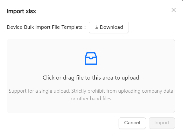
Click Import nodes to import the nodes in bulk.

3.

Click Dowload to download the node bulk import file template.

4.

For each node you want to import, enter its information in the appropriate columns in the dowloaded Excel sheet.

5.

In the Import xlsx dialog box, select the Excel sheet.

Figure 5. Import nodes
Screenshot of Import nodes
Screenshot of Bulk Import File

The sample bulk import template file includes these fields that you must fill out before importing the Excel sheet:

Table 2. Bulk Import File Template

Name

Description

Node Name

Name of the node Cisco Optical Site Manager node.

Note

This name replaces the already configured Cisco Optical Site Manager node name.

Node IP

The IP address of the node you are adding.

Note

Ensure that this IP does not overlap the Reserved internal IP addresses and subnets.

User Name

The username for accessing the new node.

Note

Use an administrator account to add and manage a Cisco Optical Site Manager node in Cisco Optical Network Controller. This account is required for onboarding and ongoing node operations, including performance monitoring collection, service provisioning and deletion, database backup and restore, and software download and activation. Other Cisco Optical Site Manager user roles are not supported for these operations.

Password

The password for accessing the new node.

Connectivity Type

The type of the protocol used for connecting the node.

Default: NETCONF

Connectivity Port

The port number of the node.

Port number 2022 for NCS 1000 series nodes.

Port number 830 for NCS 2000 series nodes.

Site Name

The name of the site to which the new node belongs.

Site Description

The description of the site to which the new node belongs.

Product Type

Set it as Cisco Optical Node.

Latitude

Specify the latitude co-ordinate value you want to assign to the new node to set its location on the map.

Longitude

Specify the longitude co-ordinate value you want to assign for the new node to set its location on the map.

After you upload the file, Cisco Optical Network Controller validates the entries and displays the message Import in progress while the nodes are being onboarded.

The new nodes are onboarded and added to the Nodes table. Wait until all nodes have completed onboarding.


Export nodes on Cisco Optical Network Controller

Use this procedure to export nodes on Cisco Optical Network Controller in Cisco Optical Network Controller. Complete this task when you need to configure, verify, or manage the related network operation.

Use this task when you need to export nodes on Cisco Optical Network Controller.

Before you begin

For exporting the node details from the table use the procedure given below.

Follow these steps to export nodes on Cisco Optical Network Controller:

Procedure

1.

Click Nodes in the left panel.

2.

Click Export to export the details to a spreadsheet file.

The export nodes on Cisco Optical Network Controller task is complete.


Edit nodes on Cisco Optical Network Controller

Use this procedure to edit nodes on Cisco Optical Network Controller in Cisco Optical Network Controller. Complete this task when you need to configure, verify, or manage the related network operation.

Use this task when you need to edit nodes on Cisco Optical Network Controller.

Before you begin

Use the Edit option for editing the node details, use the procedure given below.

Follow these steps to edit nodes on Cisco Optical Network Controller:

Procedure

1.

Click Nodes in the left panel.

2.

Click EDIT after selecting the node from the table.

In the edit mode the Cisco Optical Site Manager (COSM) geo location latitude and longitude values appear as separate values which can also be modified as required. Once the onboarding of the node or device is complete you can edit any selected node and modify its credentials using the EDIT option.

The edit nodes on Cisco Optical Network Controller task is complete.


Delete nodes on Cisco Optical Network Controller

Use this task to delete one or more nodes from Cisco Optical Network Controller.

Cisco Optical Network Controller supports node deletion even if OXC circuits. This operation does not affect traffic and you can add the same node back later.

When a node is deleted, Cisco Optical Network Controller takes these actions for the deleted nodes.

  • All alarms for the deleted node are removed from the Current Alarms tab and retained in the History Alarms tab.

  • Audit logs for the deleted node are retained

  • PM history for the deleted node is removed.

This table describes circuit behavior when a node is deleted:

Table 3. Circuit behavior after node deletion
Circuit type When the deleted node is... Service behavior in Service Manager app
CPCE A node through which the service passes. Service is deleted.
The terminal node of the service. Service is deleted.
A combination of terminal node and a node through which the service passes. Service is deleted.
GMPLS A destination node or/and a node through which the service passes.

Service is not deleted and moves to the PARTIAL state.

Note

For the TAPI notification northbound interface, the service is marked as PENDING REMOVAL when the service is in the PARTIAL state.

The source node of the service. Service is deleted.
All nodes in the service. Service is deleted.

Follow these steps to delete nodes on Cisco Optical Network Controller.

Before you begin

Follow these steps to delete nodes on Cisco Optical Network Controller:

Procedure

1.

Click Nodes in the left panel.

2.

Select the node or nodes that you want to delete.

3.

Click Delete.

The selected node is deleted from the table.

Note
  • Wait at least 2 minutes after device discovery completes before you delete the device.

  • Node deletion is not allowed when the node status is Resync In-Progress, regardless of whether the node has any services. In this case you will receive an error message for the Node Deletion Failure when the circuit is spanning through the node.

  • When an OXC is deleted from Cisco Optical Site Manager or the XR CLI, the Lifecycle State in the Service Manager application of the service connected to the OXC changes from INSTALLED to PARTIAL.

A warning message is displayed.
4.

Review the impacted services as described in the warning message.

5.

In the Delete Node dialog box and click Delete.

The selected nodes are deleted from Cisco Optical Network Controller.


Node troubleshooting information

Use this reference to understand node troubleshooting information.

Node troubleshooting information includes:

  • The most common problems encountered while adding new nodes are given below.

  • Bulk import failure In this case you will get a text file describing the specific issues in the template. Cisco ONC does not allow deletion of a node which involved in the collection or resync process, or while it is a part of any circuit path.

  • Nodes possible status Details Node Status Description User Action In Progress Cisco ONC is collecting information about the onboarded device. No action is needed, wait for the status to change. Resync Pending Cisco ONC has gone out of sync with device and is scheduled for a resync. Either wait for scheduled resync or start the resync manually. Resync In-progress Cisco ONC is re-collecting information about the onboarded devices. No action is needed, wait for the status to change. Disconnected Cisco ONC was unable to establish a session with COSM. Attempt re-connect or resync. If the problem still persists contact Cisco TAC. Discovery Completed Active All information has been collected from the device and it is ready for operations. It is recommended to wait for 60 secs once the device is turned to Discovery Completed Active state which ensures the device is ready for accepting requests.

  • Nodes connection status Details Connection State Description User Action Connected Cisco ONC has successfully established the session with the COSM device provided user/password information. No action is needed. Disconnected Cisco ONC was unable to establish session with COSM. Attempt re-connect or resync. If the problem still persists contact Cisco TAC. Waiting for connection Cisco ONC is attempting to establish connection with COSM. No action is needed. Resync_needed Cisco ONC has gone out of sync with device and is scheduled for a resync. Either wait for scheduled resync or start the resync manually. Resync Failed Cisco ONC was unable to resync after multiple retries. Attempt Resync. If problem still persists contact Cisco TAC. Discovery Failed Cisco ONC was not able to collect information from the device as it might have timed out or failed. Attempt Resync. If problem still persists contact Cisco TAC. Errored Cisco ONC was not able to collect information from the device even after 3 retries. Attempt Resync. If problem still persists contact Cisco TAC.

  • De-boarding of a node fails.

  • Ensure no circuit is created involving this node.

  • Retry deleting the node after sometime.

  • In case the deletion fails even after you have retried it multiple times, contact Cisco TAC for further assistance.


Test connectivity from Cisco Optical Network Controller to a Cisco Optical Site Manager node

Use this procedure to test connectivity from Cisco Optical Network Controller to a Cisco Optical Site Manager node in Cisco Optical Network Controller. Complete this task when you need to configure, verify, or manage the related network operation.

You can run these diagnostics while you add a node or after the node is onboarded.

Before you begin

Follow these steps to test connectivity from Cisco Optical Network Controller to a Cisco Optical Site Manager node.

Procedure

1.

Open the connectivity test for the node.

  • To test connectivity during adding a new node, in the Node Node dialog box, click Test Connection after adding the node details.

    For detailed steps, see Add nodes on Cisco Optical Network Controller.

  • To test connectivity after onboarding, on the Nodes page, select the node, click Actions, and choose Test Connection.

The Test Connection dialog opens for the selected node and shows the node name, node IP address, node port, connection status, and test duration.

2.

Click Try Again if you want to rerun the connection test.

3.

Click Ping if you want to verify node reachability from Cisco Optical Network Controller.

The ping result shows the reachability status and test duration for the selected Cisco Optical Site Manager node.

4.

Click Try Again if you want to rerun the connection test.

The test connectivity from Cisco Optical Network Controller to a Cisco Optical Site Manager node task is complete.