Cisco Optical Network Controller Configuration Guide, Releases 26.x.x

PDF

Cisco Optical Network Controller Configuration Guide, Releases 26.x.x

Service Manager application

Want to summarize with AI?

Log in

This section explains the Service Manager application, including supported circuit types, service creation, and service management options. Use it to understand service workflows before provisioning circuits.


Service manager application is a Cisco Optical Network Controller capability that

  • supports the related optical network management workflow,

  • provides context for configuration, monitoring, or troubleshooting tasks, and

  • helps operators understand how the feature behaves before they use it.

Service manager application details

The Service Manager is an application within the Cisco Optical Network Controller that provides a centralized view and management of network services, particularly circuits. It enables users to visualize, provision, and monitor circuits, and perform actions such as editing and deleting them.

Supported Circuit Types

  • OCH-NC

  • OCH-Trail

  • OCH-CC

GMPLS Support

  • Supports OCH-CC with NCS1004 chassis with the following cards:

  • NCS1K4-1.2T-K9

  • NCS1K4-OTN-XP

  • NCS1K4-2-QDD-C-K9

  • NCS1K4-QXP-K9

  • Support OCH-CC with NCS1014 chassis with the following cards:

  • NCS1K4-QXP-K9

  • NCS1K14-2.4T-X-K9

  • Supports OCH-CC and OCH-TRAIL with the following NCS2K Transponder/Muxponder

  • NCS2K-400G-XP (with card mode: MXP)

  • 15454-M-10X10G-LC (with card mode: TXP-10G and MXP-10x10G)

  • NCS2K-200G-CK-C (with card mode TXP-100G and MXP-10x10G)

  • Supports OCH-TRAIL with the following NCS2K Transponder/Muxponder

  • NCS2K-400G-XP (with card mode: OTN-XP)

  • Supports OCH-NC with alien wavelength

Existing CPCE circuits

Existing circuits are circuits that are already existing on devices. The configuration of these circuits is done either outside of Cisco Optical Network Controller, using Site Manager or CLI. It can be configured through a different instance of Cisco Optical Network Controller as well which manages the same network. The existing circuit's service names have the following format: onc_<SourceNode-Name>_<Source-Port>_<DestinationNode-Name>_<Destination-Port>.

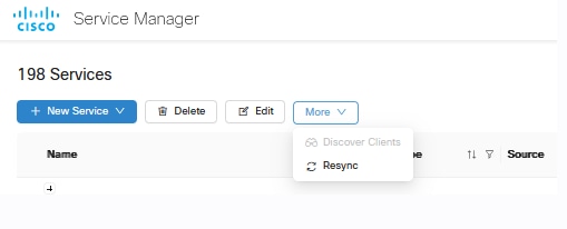
Resync services

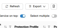
  • You can select multiple services and use the resync option to resynchronize them.

    Figure 1. Select multiple toggle
    screenshot of app
    Figure 2. Resync option for GMPLS circuits
    screenshot of app
  • Resyncing can resolve lifecycle state issues, for example, when the circuit is in PARTIAL, where clients are not discovered properly or are in an ambiguous state.

  • When multiple services are selected, the More button is replaced with a Resync button.

  • Resyncing a trail service also resyncs all its embedded OCH-CC services.

Service Manager table view toggles

  • Click Service on top toggle to toggle the Service on top mode on or off. When Service on top is enabled, the OCH-CC circuit is the main entry and its associated trail appears nested under it. When disabled, the trail becomes the main entry and the OCH-CC circuit is shown nested under it.

  • Click Select multiple toggle to toggle multiple selection in the table on or off.

    Figure 3. Service on top and Select multiple toggles
    screenshot of app

Service summary

Click i next to the name of a service to view the Summary information for a circuit. This includes all the parameters set during circuit creation or edit.
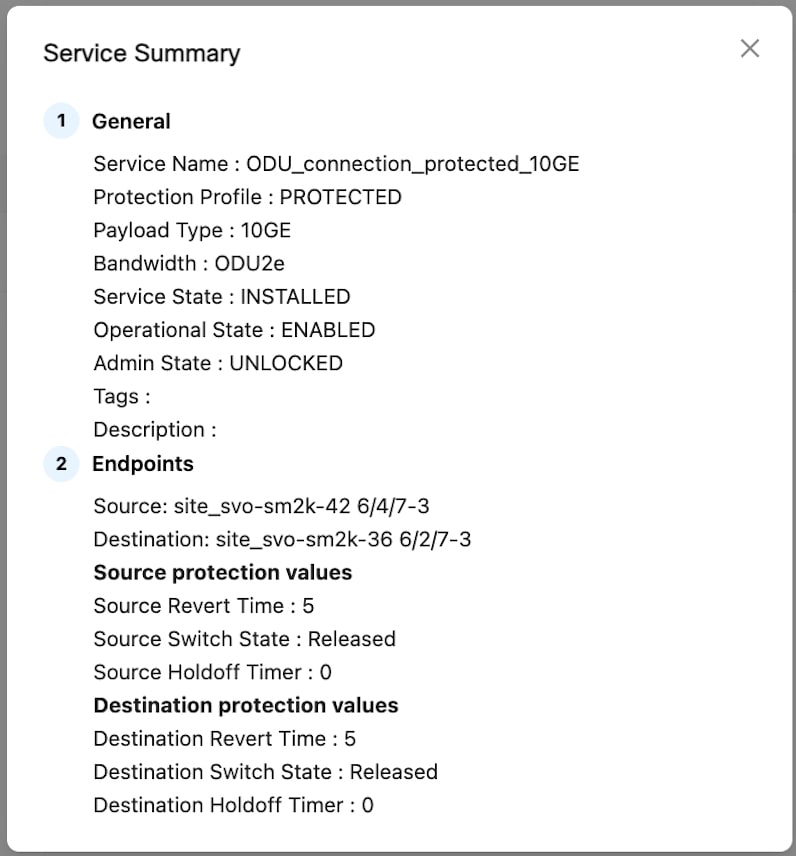
Figure 4. Service summary in service manager

Service manager table fields

Table 1. Details
Column Values Description
Name Name of the service
Type OCH-NC Type of the service
OCH-Trail
OCH-CC
Source Source Node and Port
Destination Destination Node and Port
Control Plane GMPLS Control Plane Protocol
CPCE
Lifecycle State INSTALLED The circuit is fully provisioned and active in the network.
PLANNED The circuit configuration is defined but not yet provisioned on the network.
PENDING_REMOVAL The circuit is marked for deletion but the deletion process is not yet complete.
DELETION_IN_PROGRESS The circuit deletion process is in progress.
DELETION_FAILED The circuit deletion process failed to complete successfully.
PARTIAL The circuit is in a partially provisioned state, possibly due to missing or undiscovered components.
GMPLS_ACTIVE GMPLS circuit is successfully working, cross corrections are created, and path is available.
GMPLS_INACTIVE There is no valid path for creating the circuits due to frequency not available, inconsistent constraints, optical validation failure, etc.
GMPLS_HANDOVER The circuit is configured to be upgraded from non-GMPLS to GMPLS or GMPLS to non-GMPLS.
GMPLS_ACTIVATING GMPLS circuit activation is in progress
GMPLS_DEACTIVATING GMPLS circuit deactivation is in progress.
GMPLS_FAILED GMPLS circuit failed (i.e. link down, node down).
GMPLS_DEGRADED Circuit trail failed (i.e. PSM working or protected is down or fail).
GMPLS_RECOVERING Temporary reboot status at circuit restart.
GMPLS_REPAIRING Circuit repair is in progress (i.e. node IP changed)
GMPLS_RELEASING A downgrade from GMPLS to non-GMPLS circuit has been requested and the action is running.
GMPLS_REPAIR_NEEDED An IP address change is done on a node impacting the circuit, so the circuit must be repaired.
Note

Cisco Optical Network Controller does not support circuit repair in release 25.1.1.

GMPLS_SYNC_IN_PROGRESS GMPLS controller has acceptedthe configuration, Cisco Optical Network Controller is getting the updated data from the GMPLS controller. When a circuit is discovered in a node that is onboarded to CONC , the Lifecycle state continues in this state until CONC fetches the circuit information from the GMPLS controller.
Operational State ENABLED The circuit is active and functioning normally.
DISABLED The circuit is inactive and not functioning.
Admin State UNLOCKED The circuit is administratively enabled and available for use.
LOCKED The circuit is administratively disabled and unavailable for use.
Frequency (THz) Optical carrier frequency at which the circuit will operate within the DWDM spectrum.
Bandwidth (GHz) Bandwidth used by the circuit
Protection profile PROTECTED OTN service has both active and standby path.
UNPROTECTED

For OTN service, only active path is present.

For PSM circuit, the circuit is configured with PSM OMS protection.

OCH-PSM

The circuit is configured with PSM wavelength protection to ensure service availability in case of failure.
Port Rate 10GE Data rate
40GE
100GE
400GE
OTU2
OTU2E
OTU4
OC192/ STM-64
FC16
FC32
Discovery Date Service discovery date
Restoration Type None No restoration is configured for the circuit.
Enabled Restoration is enabled for the circuit, and the network will automatically attempt to restore the circuit upon failure by calculating restoration path based on restoration constraints.
Restorable Alternate Restoration is enabled for the circuit, and the network will automatically attempt to restore the circuit upon failure by calculating restoration path based on restoration constraints and main path constraints alternatively.
Enabled and Revertive(Automatic) Restoration is enabled, and the circuit will automatically revert to the original (home) path after the failure is resolved and unverified alarms are manually cleared from COSM.
Enabled and Revertive(Manual) Restoration is enabled, and manual intervention is required to revert the circuit to the original (home) path after the failure is resolved.
Tags Tags attached to the Service during circuit provisioning.

CPCE service endpoints and operations

Provisioning CPCE services involves creating service endpoints, reviewing the conditions for circuit creation, and managing lifecycle operations such as resynchronizing nodes or updating card modes.

Conditions for Creating OCH-CC Circuits

Consider these conditions when creating OCH-CC circuits.

  • The OCH-Trail must be in installed state before an OCH-CC circuit can be created.

  • When the corresponding trail is in planned state, no new OCH-CC circuits can be created.

  • The number of OCH-CC circuits that you can have per trail depends on the card mode configuration of the transponder card.

  • OCH-CC circuits inherit constraints from the parent trail.

  • Creating an OCH-CC circuit creates the associated OCH-Trail circuit automatically.

Provisioning requirements

Note
  • After changing the card mode for NCS1K4-1.2T-K9, resync the nodes from the Nodes page to ensure that the client ports are correctly displayed.

  • If you do not see the ports on your target nodes during endpoint selection, we recommend you perform a resync of the nodes before creating a new service.

  • If a new NCS 2000 chassis with a TXP present is added to a node already present in COSM, you must perform a resync of the node to see the endpoints during circuit provisioning.

Completion state

The create and manage CPCE services task is complete.

Supported cards and provisioning options

This table describes the supported cards and their modes that can be used to create and manage circuits.

Table 2. Supported transponder cards and modes

Card

Modes Supported

NCS1K4-2-QDD-C-K9

MXP-SLICE: 200G, 300G, 400G trunk and 100G and OTU4 client

NCS1K4-QXP-K9

MXP-SLICE: 400G trunk with 400G and 100G client

NCS1K4-OTN-XP

MXP: 4x100G

TXP: 400G

400G trunk with 100G, 10G and OTU2 clients

NCS1K14-2.4T-X-K9

MXP-SLICE: 400G, 600G, 800G, 1T, 1.2T trunk with 100G and 400G clients

NCS1K4-1.2T-K9

MXP: 100G, 200G, 300G, 400G trunk with 100G and OTU4 client

MXP-SLICE: 2 trunks with 100G, 200G, 300G, 400G bandwidth and 100G and OTU4 client

Supports SD-FEC-27 and SD-FEC-15

NCS2K-400G-XP-LC

MXP: 400G trunk and 100G, 10G clients

FEC Modes: SD_FEC_15_DE_OFF, SD_FEC_15_DE_ON, SD_FEC_25_DE_OFF, SD_FEC_25_DE_ON

NCS2K-200G-CK-C

TXP-100G: 100G trunk and client

FEC Modes: HG_FEC_7, SD_FEC_20, SD_FEC_25_DE_OFF, SD_FEC_25_DE_ON

NCS2K-1.2T-MXP

TXPMXP: 400G Trunk and 100GE, 400GE, and OTU4 clients

This table summarizes the additional supported circuit provisioning options for the 400G-XP-LC cards across CPCE configurations.

Table 3. Supported circuit provisioning options for 400G-XP-LC cards

Configuration

OCH-CC

OCH-Trail

OCH-NC

NCS2000 400G-XP-LC with peered ONS 15454 10x10G-LC

Yes

Yes

Yes

10X10G with MPO cable connected to 400G-XP-LC

No

Yes

Yes


CPCE service troubleshooting information

Use this reference to understand CPCE service troubleshooting information.

CPCE service troubleshooting information includes:

  • Some PCE error codes which you might encounter while provisioning the service are given below.

  • [PCE-PR00003] - Failed for waves selector: [PCE-EXC00002] - Carrier 1 source wave (XXXXXXXX-XXXXX (XXXX.XX)) and Destination one (XXXXXXXX-XXXXX (XXXX.XX)) differs.

  • [PCE-WAL00048] - Requested central frequency XXX,XXX is out of supported range.

  • [PCE-WAL00026] - No free spectrum available to allocate MCH with central frequency XXX.XXX.

  • [PCE-PR00001] - No routes available.

  • [PCE-WAL00026] - No free spectrum available to allocate MCH with central frequency XXX.XXX.x.

  • [PCE-PR00026] - Include constraint [Site uuid] not matched.

  • [PCE-PR00018] - Optical validation failed: ZONE_RED worse than ZONE_GREEN.

  • [PCE-PR00004] - Failed to evaluate optical path: [PCE-OV00016] - [Fiberspan UUID]: Invalid fiberType: [null value].

Table 4. Details
Failure Scenario Cisco ONC Error Recovery Step
Cisco Optical Site Manager Node gets disconnected as soon as a service is provisioned in CONC Config Failure

Delete the circuit and reprovision from the CONC.

Cisco Optical Site Manager nodes are in sync state during CONC provisioning.

Config Failure

Check the Cisco Optical Site Manager node and wait for synchronisation to complete.

NCS 1010 Devices under Cisco Optical Site Manager Nodes are locked

Config Failure
  • Check Cisco Optical Site Manager and unlock the NCS 1010 device.

  • Verify Cisco Optical Site Manager synchronisation status to be completed.

Cisco Optical Site Manager node Restart during provisioning Config Failure

Wait for CONC to re-establish the connection successfully after restart and its status moved to Active in CONC.

Reload of the NCS 1010 device during provisioning from CONC

Config Failure
  • Wait for the reload to complete on NCS 1010 device.

  • Verify the synchronisation is complete on Cisco Optical Site Manager Node.

  • Wait for CONC to reestablish the connection successfully with Cisco Optical Site Manager Node and its status moved to Active.

Stale entries present in NCS 1010 while no cross connects present on Cisco Optical Site Manager Nodes Config Failure
  • Clear the NCS1010 stale entries.

  • Wait for Cisco Optical Site Manager node to complete the synchronisation.

Xcons Present in Cisco Optical Site Manager node along with NCS 1010 Config Failure
  • Clear the XCONS on Cisco Optical Site Manager and NCS 1010.

  • Wait for Cisco Optical Site Manager node to complete the synchronisation and Active status.

CPCE service troubleshooting information details

The probable scenarios in which the services can go to the Pending Removal State due to configuration failures and recovery steps are given below:.

CPCE service troubleshooting information details

The most common problems encountered while using the Service Manager application is given below.


Create CPCE services

Create a CPCE service by selecting endpoints and configuring circuit parameters.

Consider these conditions when creating OCH-CC circuits.

  • The OCH-Trail must be in installed state before an OCH-CC circuit can be created.

  • When the corresponding trail is in planned state, no new OCH-CC circuits can be created.

  • The number of OCH-CC circuits that you can have per trail depends on the card mode configuration of the transponder card.

  • OCH-CC circuits inherit constraints from the parent trail.

  • Creating an OCH-CC circuit creates the associated OCH-Trail circuit automatically.

Follow these steps to create circuits in Cisco Optical Network Controller.

Before you begin

Note
  • After changing the card mode for NCS1K4-1.2T-K9, resync the nodes from the Nodes page to ensure that the client ports are correctly displayed.

  • If you do not see the ports on your target nodes during endpoint selection, we recommend you perform a resync of the nodes before creating a new service.

  • If a new NCS 2000 chassis with a TXP present is added to a node already present in COSM, you must perform a resync of the node to see the endpoints during circuit provisioning.

Follow these steps to create and manage CPCE services:

Procedure

1.

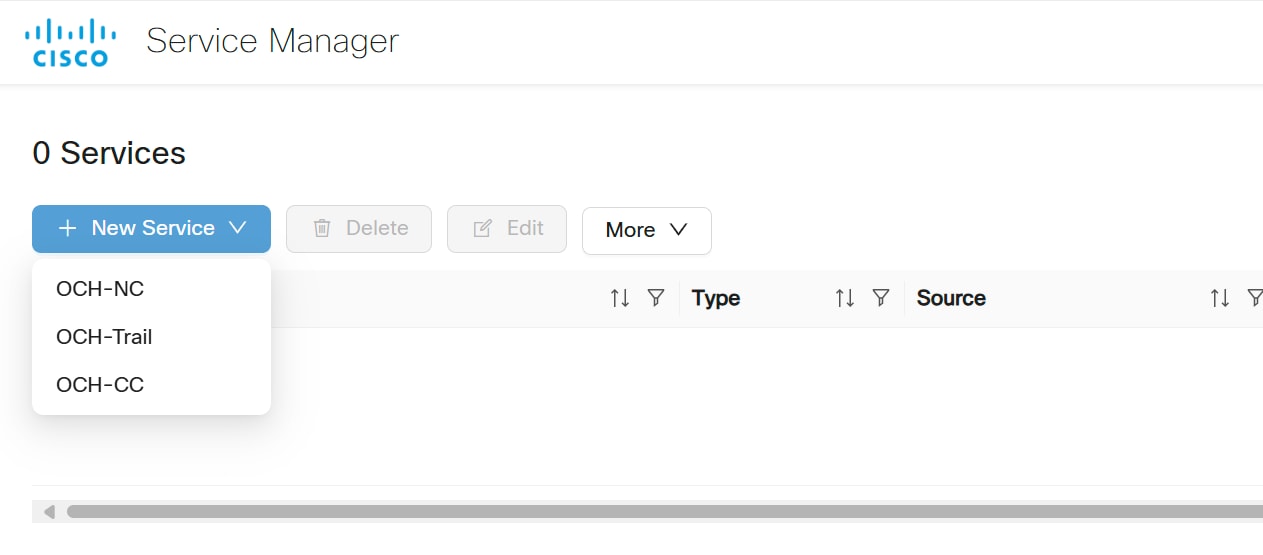
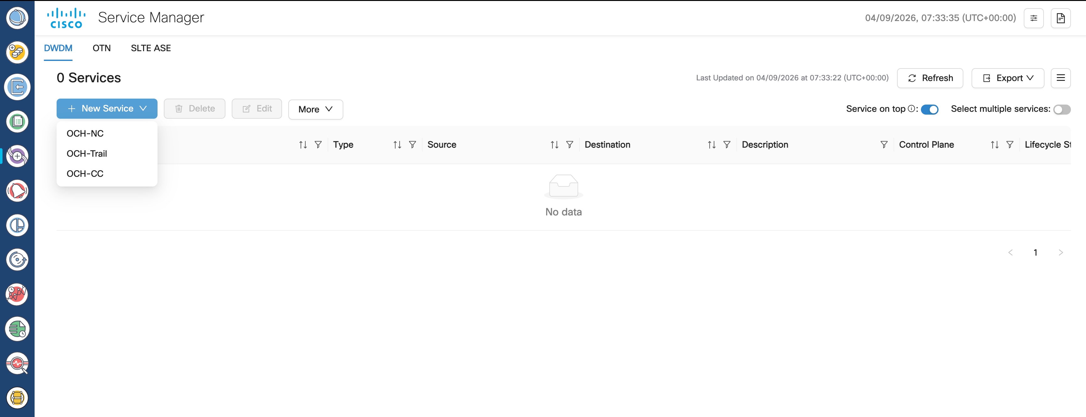
Click New Service and choose OCH-NC, OCH-Trail, or OCH-CC.

screenshot of links app
2.

Select OCH-NC, OCH-Trail, or OCH-CC.

Note
  • OCH-NC: An OCH-NC is a circuit established between add/drop ports on terminal OLTs (Optical Line Terminals) or ROADMs (Reconfigurable Optical Add-Drop Multiplexers). This type of circuit typically connects end-user equipment to the optical network.

  • OCH-Trail: An OCH-Trail is a circuit established between trunk ports of transponders or muxponders. This type of circuit typically transports aggregated traffic across the optical core network.

  • OCH-CC: An OCHCC circuit is an optical service type that extends the OCH-NC to create an optical connection from the source client port to the destination client port of the transponder or muxponder cards. It also represents the actual end-to-end client service passing through the DWDM system, and enables seamless client traffic transmission across the optical network.

Figure 5. Service Manager
screenshot of links app
Service Manager launches the new service wizard.
3.

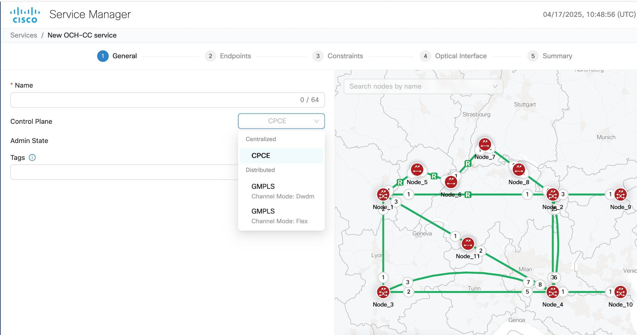
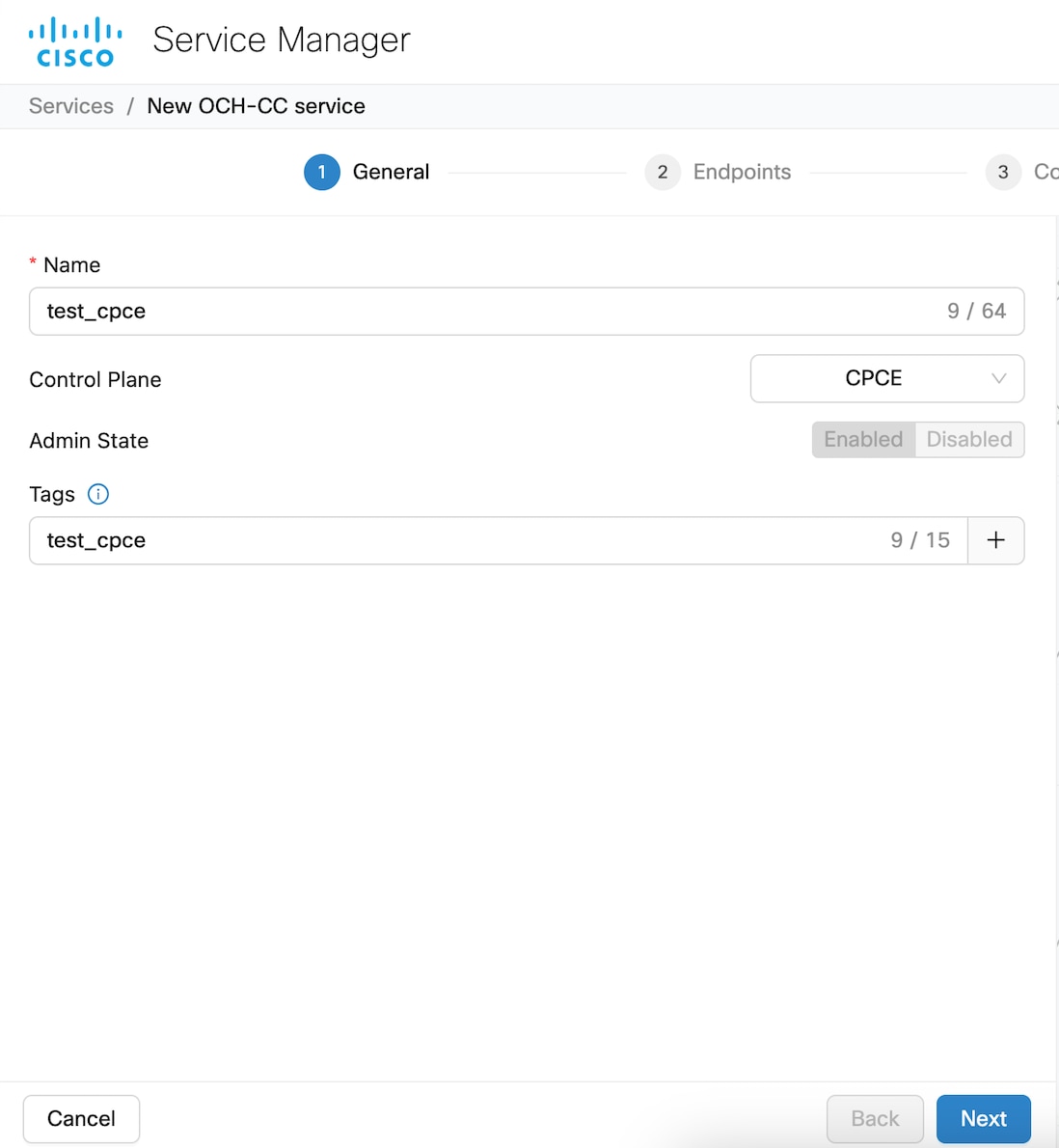
Enter the details in the General tab and click Next.

Figure 6. Service Manager
screenshot of links app
Table 5. General Parameters
Field Description Values/restrictions
Name The unique user defined name of the link. (Allowed characters are a-z, A-Z, 0-9 and _. <Space not allowed>).
Control Plane CPCE
Admin State only ENABLED is supported
Tags Tags can be attached to the Service for better management, to group them together
Note

Click + after entering a tag to add a tag. You can add multiple tags. if you click Next without clicking + the tag is not added to the service.

4.

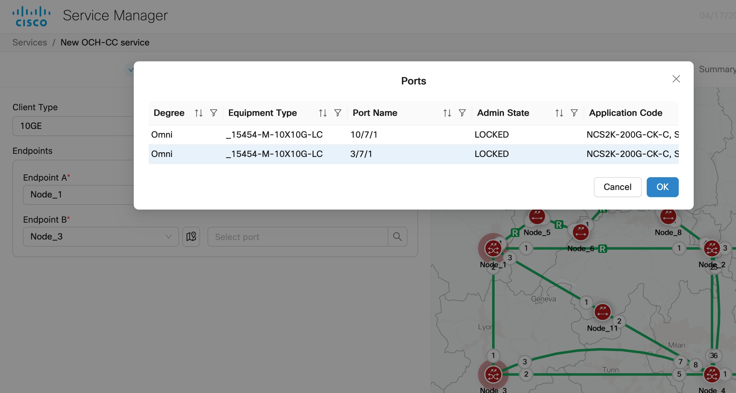
Choose a Carrier type and the endpoints of the circuit in the Endpoints tab, and click Next.

Figure 7. Service Manager
screenshot
Table 6. Endpoints Parameters
Field Description Values/restrictions
Carrier Type
Single Carrier Provision a service between 2 nodes with source and destination end points.
Multi-Carrier Provision a service between 2 nodes with multiple source and destination end points. Only for OCH-NC circuits
Endpoints
Endpoint A Node and port of first endpoint
Endpoint B Node and port of second endpoint
Note
  • Click and select any object from the map after clicking the map icon and that object's details gets added in the Endpoints automatically.

  • Click Add Endpoint to add additional endpoints to multicarrier services.

  • When you create a OCH-CC circuit for an existing trail, after selecting the first endpoint, the second endpoint is auto filled. The constraints and optical interface tabs are also skipped. You are taken directly to the summary tab. The preview option is not available.

5.

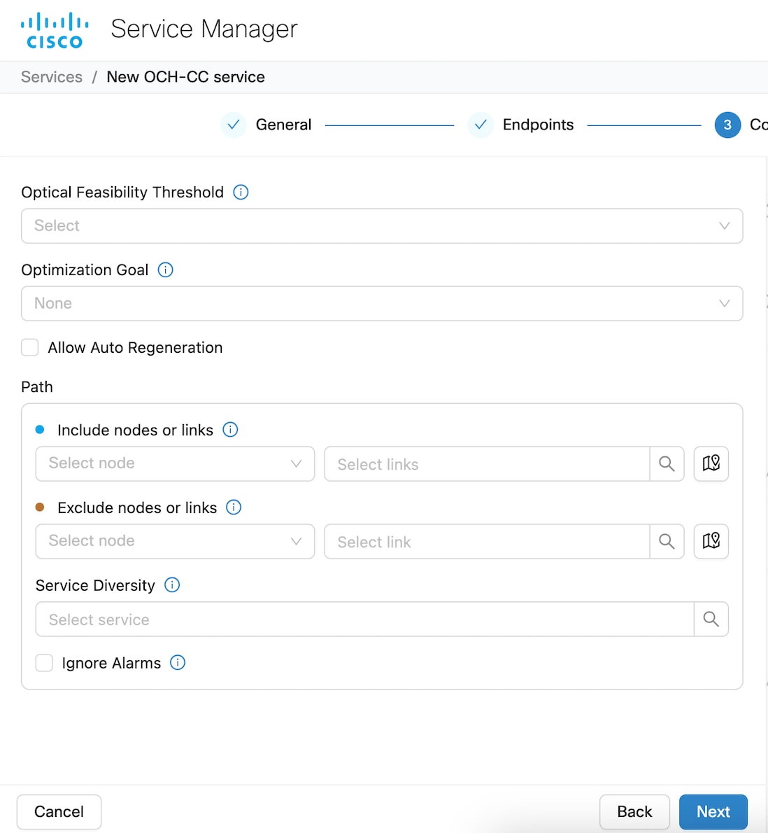
Choose the constraints in the Constraints tab, and click Next.

Figure 8. Service Manager
screenshot
Table 7. Constraint parameters
Field Description Values/restrictions
Optical Feasibility Threshold Indicates the optical feasibility of the link to ensure that the link is operational after provisioning. Select RED, GREEN, YELLOW or ORANGE. GREEN = mean value YELLOW = +1 sigma ORANGE = +2 sigma RED = +3 sigma
Optimization Goal Defines the mechanism for the control plane to compute optimum path depending on various criteria. LENGTH (Max): Computation criteria based on minimizing the path LENGTH HOPS(Max): Computation criteria based on minimizing the number of HOPS OSNR(Min): Computation criteria based on maximizing the OSNR
Allow Auto Regeneration Whether to allow auto regeneration
Path
Include nodes or links select list of nodes & links that has to be included by the control plane during path computation.
Exclude nodes or links select list of nodes & links that has to be excluded by the control plane during path computation.
Service Diversity Select one or more existing services from the dropdownfor the control plane to exclude the resources that the services use during path computation.
Ignore Alarms If true, Service manager ignores any alarms present on the path and continues to provision the service.
Note

Optical Feasibility Threshold assesses whether an optical channel is operational after provisioning based on its optical power and Optical Signal-to-Noise Ratio (OSNR). This assessment is represented by colors: RED, GREEN, YELLOW, or NONE.

6.

Choose the optical interface Parameters in the Optical Interface tab, and click Next.

Table 8. Optical interface parameters
Field Description
Wavelength
Central Frequency (THz) Choose a central frequency for the service.
Nyquist Spacing Select Yes to allow channels to share spectral boundaries as long as the center frequency of one channel does not fall within the spectrum of another.
Note

This option is only enabled if central frequency is specified.

Customer Name The Customer name
Product ID The product ID This is the Product ID of either the pluggable optics for the TXP card with pluggable trunk or the TXP card for the TXP card with fixed trunk.
FEC The FEC depending on the product, for example, CFEC or OFEC depending on the previous selection.
Data Rate The Data rate supported by the selected product.
Baud rate The Baud rate supported by the selected product.
Sub Mode is may appear depending on the other settings
Note
  • Click Reload application code to reload the list of the Application codes available for OCHNC provisioning for an Alien wavelength recently imported using Alien Import.

  • Click Reset to reset all the fields.

  • For OCH-trail,Optical Interface fields are auto populated and non-editable.

Clicking next takes you to the Summary tab.
7.

Click Preview in the Summary tab to the preview the circuit in the topology before it is created.

8.

Click Finish to create the circuit.

9.

Click OK once the circuit is provisioned successfully.

The newly provisioned circuit appears in the Service List table once the provisioning is complete. The Lifecycle State for the new circuit appears as PLANNED initially and later changes to INSTALLED.

The create and manage CPCE services task is complete.

This table describes the supported cards and their modes that can be used to create and manage circuits.
Table 9. Supported transponder cards and modes

Card

Modes Supported

NCS1K4-2-QDD-C-K9

MXP-SLICE: 200G, 300G, 400G trunk and 100G and OTU4 client

NCS1K4-QXP-K9

MXP-SLICE: 400G trunk with 400G and 100G client

NCS1K4-OTN-XP

MXP: 4x100G

TXP: 400G

400G trunk with 100G, 10G and OTU2 clients

NCS1K14-2.4T-X-K9

MXP-SLICE: 400G, 600G, 800G, 1T, 1.2T trunk with 100G and 400G clients

NCS1K4-1.2T-K9

MXP: 100G, 200G, 300G, 400G trunk with 100G and OTU4 client

MXP-SLICE: 2 trunks with 100G, 200G, 300G, 400G bandwidth and 100G and OTU4 client

Supports SD-FEC-27 and SD-FEC-15

NCS2K-400G-XP-LC

MXP: 400G trunk and 100G, 10G clients

FEC Modes: SD_FEC_15_DE_OFF, SD_FEC_15_DE_ON, SD_FEC_25_DE_OFF, SD_FEC_25_DE_ON

NCS2K-200G-CK-C

TXP-100G: 100G trunk and client

FEC Modes: HG_FEC_7, SD_FEC_20, SD_FEC_25_DE_OFF, SD_FEC_25_DE_ON

NCS2K-1.2T-MXP

TXPMXP: 400G Trunk and 100GE, 400GE, and OTU4 clients

This table summarizes the additional supported circuit provisioning options for the 400G-XP-LC cards across CPCE configurations.

Table 10. Supported circuit provisioning options for 400G-XP-LC cards

Configuration

OCH-CC

OCH-Trail

OCH-NC

NCS2000 400G-XP-LC with peered ONS 15454 10x10G-LC Yes Yes Yes
10X10G with MPO cable connected to 400G-XP-LC No Yes Yes

Manage CPCE services

Review existing CPCE services and perform supported lifecycle operations.

Consider these conditions when creating OCH-CC circuits.

  • The OCH-Trail must be in installed state before an OCH-CC circuit can be created.

  • When the corresponding trail is in planned state, no new OCH-CC circuits can be created.

  • The number of OCH-CC circuits that you can have per trail depends on the card mode configuration of the transponder card.

  • OCH-CC circuits inherit constraints from the parent trail.

  • Creating an OCH-CC circuit creates the associated OCH-Trail circuit automatically.

Follow these steps to create circuits in Cisco Optical Network Controller.

Before you begin

Note
  • After changing the card mode for NCS1K4-1.2T-K9, resync the nodes from the Nodes page to ensure that the client ports are correctly displayed.

  • If you do not see the ports on your target nodes during endpoint selection, we recommend you perform a resync of the nodes before creating a new service.

  • If a new NCS 2000 chassis with a TXP present is added to a node already present in COSM, you must perform a resync of the node to see the endpoints during circuit provisioning.

Follow these steps to create and manage CPCE services:

Procedure

1.

Select a service and click Edit to edit the circuit.

  1. Update the name.

  2. Click Save.

2.

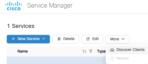
Select an OCH-Trail circuit and click More > Discover Clients to discover all OCH-CC circuits over the selected trail.

Figure 9. Service Manager
screenshot
3.

Click Delete option to delete a selected service from the table.

Note

Delete each OCH-CC circuit associated with a service and then delete the OCH-Trail circuit.

Note

When cross-connect endpoints are extended or modified in Cisco Optical Site Manager or NCS 1000 topology, the existing service becomes outdated and its Lifecycle Statemoves to Pending Removal, while a new service with the updated endpoints is automatically rediscovered in Service Manager. After the new service is visible, the old pending-removal service can be safely deleted without affecting the network.

4.

Click + icon after selecting any service to expand the service and view its carriers.

Carriers can be of either single or multiple service types. Multiple carriers can have the same Endpoints over different channels.

The create and manage CPCE services task is complete.

This table describes the supported cards and their modes that can be used to create and manage circuits.
Table 11. Supported transponder cards and modes

Card

Modes Supported

NCS1K4-2-QDD-C-K9

MXP-SLICE: 200G, 300G, 400G trunk and 100G and OTU4 client

NCS1K4-QXP-K9

MXP-SLICE: 400G trunk with 400G and 100G client

NCS1K4-OTN-XP

MXP: 4x100G

TXP: 400G

400G trunk with 100G, 10G and OTU2 clients

NCS1K14-2.4T-X-K9

MXP-SLICE: 400G, 600G, 800G, 1T, 1.2T trunk with 100G and 400G clients

NCS1K4-1.2T-K9

MXP: 100G, 200G, 300G, 400G trunk with 100G and OTU4 client

MXP-SLICE: 2 trunks with 100G, 200G, 300G, 400G bandwidth and 100G and OTU4 client

Supports SD-FEC-27 and SD-FEC-15

NCS2K-400G-XP-LC

MXP: 400G trunk and 100G, 10G clients

FEC Modes: SD_FEC_15_DE_OFF, SD_FEC_15_DE_ON, SD_FEC_25_DE_OFF, SD_FEC_25_DE_ON

NCS2K-200G-CK-C

TXP-100G: 100G trunk and client

FEC Modes: HG_FEC_7, SD_FEC_20, SD_FEC_25_DE_OFF, SD_FEC_25_DE_ON

NCS2K-1.2T-MXP

TXPMXP: 400G Trunk and 100GE, 400GE, and OTU4 clients

This table summarizes the additional supported circuit provisioning options for the 400G-XP-LC cards across CPCE configurations.

Table 12. Supported circuit provisioning options for 400G-XP-LC cards

Configuration

OCH-CC

OCH-Trail

OCH-NC

NCS2000 400G-XP-LC with peered ONS 15454 10x10G-LC Yes Yes Yes
10X10G with MPO cable connected to 400G-XP-LC No Yes Yes

GMPLS endpoints and operations

Provisioning GMPLS services involves selecting a supported circuit type, defining compatible endpoints, configuring path and restoration constraints, and validating optical feasibility before deployment.

Supported transponder cards and modes

Table 13. Supported transponder cards and modes

Card

Modes Supported

NCS1K4-2-QDD-C-K9

MXP-SLICE: 200G, 300G, 400G trunk and 100G and OTU4 client

NCS1K4-QXP-K9

MXP-SLICE: 400G trunk with 400G and 100G client

NCS1K4-OTN-XP

MXP: 4x100G

TXP: 400G

400G trunk with 100G, 10G and OTU2 clients

NCS1K14-2.4T-X-K9

MXP-SLICE: 400G, 600G, 800G, 1T, 1.2T trunk with 100G and 400G clients

NCS1K4-1.2T-K9

MXP: 100G, 200G, 300G, 400G trunk with 100G and OTU4 client

MXP-SLICE: 2 trunks with 100G, 200G, 300G, 400G bandwidth and 100G and OTU4 client

Supports SD-FEC-27 and SD-FEC-15

NCS2K-400G-XP-LC

MXP: 400G trunk and 100g, 10G clients

FEC Modes: SD_FEC_15_DE_OFF, SD_FEC_15_DE_ON, SD_FEC_25_DE_OFF, SD_FEC_25_DE_ON

MXP with backplane connection to 15454-M-10X10G-LC with slice 2 configured as OPM-PEER-ODU2 or OPM-PEER-ODU2E

REGEN: 100G and 200G trunk regeneration for GMPLS OCH-Trail and OCH-CC circuits

NCS2K-200G-CK-C

TXP-100G: 100G trunk and client

FEC Modes: HG_FEC_7, SD_FEC_20, SD_FEC_25_DE_OFF, SD_FEC_25_DE_ON

RGN-100G: 100G trunk regeneration for GMPLS OCH-Trail and OCH-CC circuits

15454-M-10X10G-LC

MXP 10x10G (with backplane connection to NCS2k-200G-CK-C/15454-M-100G-LC-C/15454-M-100G-ME-C) 100G trunk and 10G, OTU2, OTU2e, and OC192/STM64 clients

15454-M-100G-LC-C and 15454-M-100G-ME-C

  • 10x10G client card

  • 100GE TXP mode: 100G trunk and 100GE/OTU4 clients

Note

From release 25.1.1, Cisco Optical Network Controller supports OCH-CC circuits between client ports that have the same client type and the same equipment type at both endpoints.

Note

From release 26.1.1, Cisco Optical Network Controller discovers the ODU connections and builds the end-to-end protected or unprotected OTN services. Cisco Optical Network Controller automatically discovers the full OTN service when the OCH-Trail for GMPLS circuits are discovered. Additional OTN services can be added via CTC.

In release 26.1.1, OTN services are supported in the OTN-XC card mode of the NCS2K-400G-XP-LC line card only.

Troubleshooting GMPLS provisioning errors

These are some common errors encountered during GMPLS circuit provisioning:

Table 14. Details
Error Description
No wavelength available on path

The optical path in the node terminates on a port not matching the requested protection mode.

Reroute Failed

The requested action can not be executed as the selected circuit is already in rolled state

Optical Validation The partial path evaluated during route selection is outside the receiver OSNR threshold.
No client port available on trunk port

No available Client port matching the request constraints is found connected to the TXP Trunk port

No available optical path in node No wavelength is available on the optical path.

Additional supported provisioning options

This table summarizes the additional supported circuit provisioning options for the NCS 2000 100G-LC-C and 400G-XP-LC cards across GMPLS configurations.

Table 15. Supported circuit provisioning options for 100G-LC-C/100G-ME-C and 400G-XP-LC cards

Configuration

OCH-CC

OCH-Trail

OCH-NC

NCS2000 100G-LC-C/100G-ME-C standalone Yes Yes Yes
NCS2000 100G-LC-C/100G-ME-C with peered ONS 15454 10x10G-LC Yes Yes Yes
NCS2000 400G-XP-LC with peered ONS 15454 10x10G-LC Yes Yes Yes
10X10G with MPO cable connected to 400G-XP-LC No Yes Yes

Create GMPLS services

Create a GMPLS circuit by defining its endpoints and provisioning parameters.

Review the supported configurations and troubleshooting information before provisioning a GMPLS circuit.

Before you begin

Table 16. Supported transponder cards and modes

Card

Modes Supported

NCS1K4-2-QDD-C-K9

MXP-SLICE: 200G, 300G, 400G trunk and 100G and OTU4 client

NCS1K4-QXP-K9

MXP-SLICE: 400G trunk with 400G and 100G client

NCS1K4-OTN-XP

MXP: 4x100G

TXP: 400G

400G trunk with 100G, 10G and OTU2 clients

NCS1K14-2.4T-X-K9

MXP-SLICE: 400G, 600G, 800G, 1T, 1.2T trunk with 100G and 400G clients

NCS1K4-1.2T-K9

MXP: 100G, 200G, 300G, 400G trunk with 100G and OTU4 client

MXP-SLICE: 2 trunks with 100G, 200G, 300G, 400G bandwidth and 100G and OTU4 client

Supports SD-FEC-27 and SD-FEC-15

NCS2K-400G-XP-LC

MXP: 400G trunk and 100g, 10G clients

FEC Modes: SD_FEC_15_DE_OFF, SD_FEC_15_DE_ON, SD_FEC_25_DE_OFF, SD_FEC_25_DE_ON

MXP with backplane connection to 15454-M-10X10G-LC with slice 2 configured as OPM-PEER-ODU2 or OPM-PEER-ODU2E

REGEN: 100G and 200G trunk regeneration for GMPLS OCH-Trail and OCH-CC circuits

NCS2K-200G-CK-C

TXP-100G: 100G trunk and client

FEC Modes: HG_FEC_7, SD_FEC_20, SD_FEC_25_DE_OFF, SD_FEC_25_DE_ON

RGN-100G: 100G trunk regeneration for GMPLS OCH-Trail and OCH-CC circuits

15454-M-10X10G-LC

MXP 10x10G (with backplane connection to NCS2k-200G-CK-C/15454-M-100G-LC-C/15454-M-100G-ME-C) 100G trunk and 10G, OTU2, OTU2e, and OC192/STM64 clients

15454-M-100G-LC-C and 15454-M-100G-ME-C

  • 10x10G client card

  • 100GE TXP mode: 100G trunk and 100GE/OTU4 clients

Note

From release 25.1.1, Cisco Optical Network Controller supports OCH-CC circuits between client ports that have the same client type and the same equipment type at both endpoints.

Note

From release 26.1.1, Cisco Optical Network Controller discovers the ODU connections and builds the end-to-end protected or unprotected OTN services. Cisco Optical Network Controller automatically discovers the full OTN service when the OCH-Trail for GMPLS circuits are discovered. Additional OTN services can be added via CTC.

In release 26.1.1, OTN services are supported in the OTN-XC card mode of the NCS2K-400G-XP-LC line card only.

Follow these steps to create and manage GMPLS services:

Procedure

1.

Click New Service and choose OCH-NC, OCH-Trail, or OCH-CC.

Figure 10. Service Manager
2.

Select OCH-NC, OCH-Trail, or OCH-CC.

  • OCH-NC: An OCH-NC is a circuit established between add/drop ports on terminal OLTs (Optical Line Terminals) or ROADMs (Reconfigurable Optical Add-Drop Multiplexers). This type of circuit typically connects end-user equipment to the optical network.

    Note

    You must create an LMP from COSM GMPLS > LMP panel before creating an OCH-NC circuit.

  • OCH-Trail: An OCH-Trail is a circuit established between trunk ports of transponders or muxponders. This type of circuit typically transports aggregated traffic across the optical core network.

  • OCH-CC: An OCH-CC is a circuit established between cards within optical devices, such as transponders, muxponders, or ROADMs. This type of circuit facilitates internal cross-connections within the optical equipment.

Service Manager launches the new service wizard.
3.

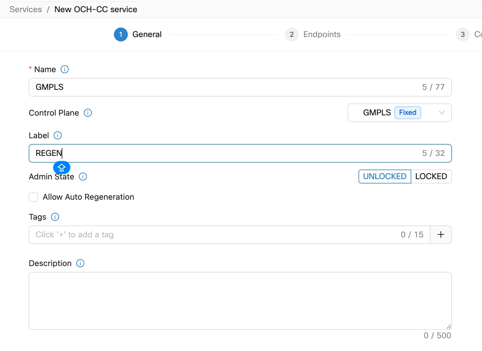
Enter the details in the General tab and click Next.

Figure 11. Service Manager > General
Table 17. General Parameters
Field Description Values/restrictions
Name The unique user defined name of the link. (Allowed characters are a-z, A-Z, 0-9 and _. <Space not allowed>).
Control Plane

GMPLS Dwdm or GMPLS Flex

Label

This label is assigned to the NCS 2000 cross-connects.

A label is autogenerated if the field is left blank.
Admin State The admin state of the service

UNLOCKED or LOCKED

Allow Auto Regeneration

Allows the control plane to find a regenerator deployed in the network when a single DWDM channel is not optically feasible end to end.

Note

This field is only displayed when GMPLS is selected in Control Plane.

Available for GMPLS OCH-Trail and OCH-CC circuits.
Tags Tags can be attached to a service for better management, to group them together.
Description Add a description about the service.
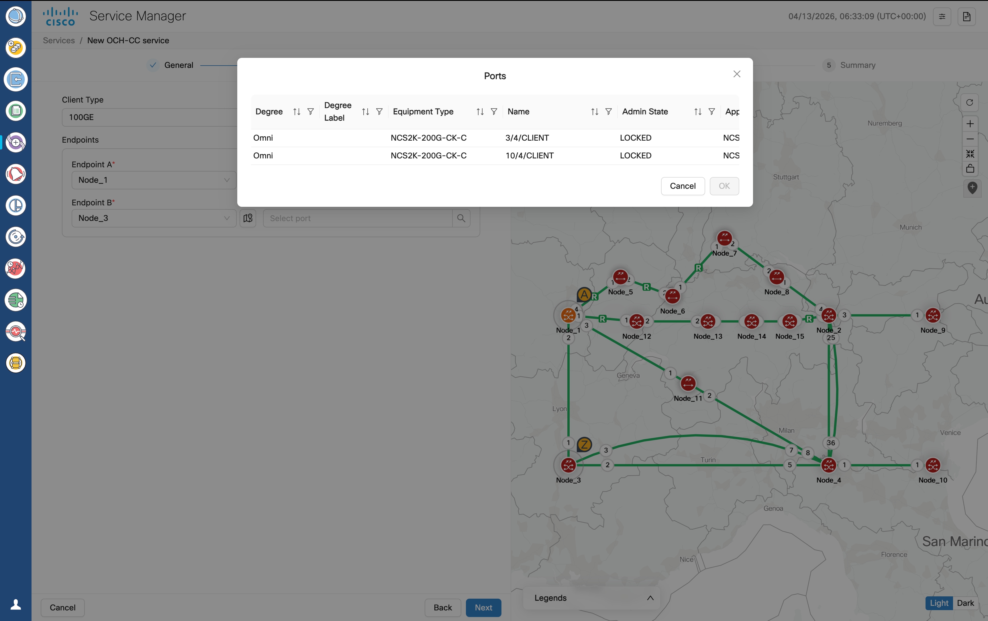
4.

Choose a client type and the endpoints of the circuit in the Endpoints tab, and click Next.

Figure 12. Service Manager > Endpoints
Table 18. Endpoints Parameters
Field Description Values/restrictions
Client Type Select the client type 10GE, 40GE, 100GE, 400GE, OTU2, OTU2E, OTU4, OC192/STM64
Endpoints
Endpoint A Node and port of first endpoint
Endpoint B Node and port of second endpoint
Note
  • Click and select any object from the map after clicking the map icon and that object's details gets added in the Endpoints automatically.

  • The port selection list shows the ports matching the client type selection.

5.

Choose the constraints in the Constraints > General tab, and click Next.

Figure 13. Service Manager > Constraints > General
Table 19. General constraints field descriptions
Field Description Values/restrictions
Optical Feasibility Threshold Indicates the optical feasibility of the link to ensure that the link is operational after provisioning. Select RED, GREEN, YELLOW or ORANGE. GREEN = mean value YELLOW = +1 sigma ORANGE = +2 sigma RED = +3 sigma
Path
Include nodes or links select list of nodes & links that has to be included by the control plane during path computation.
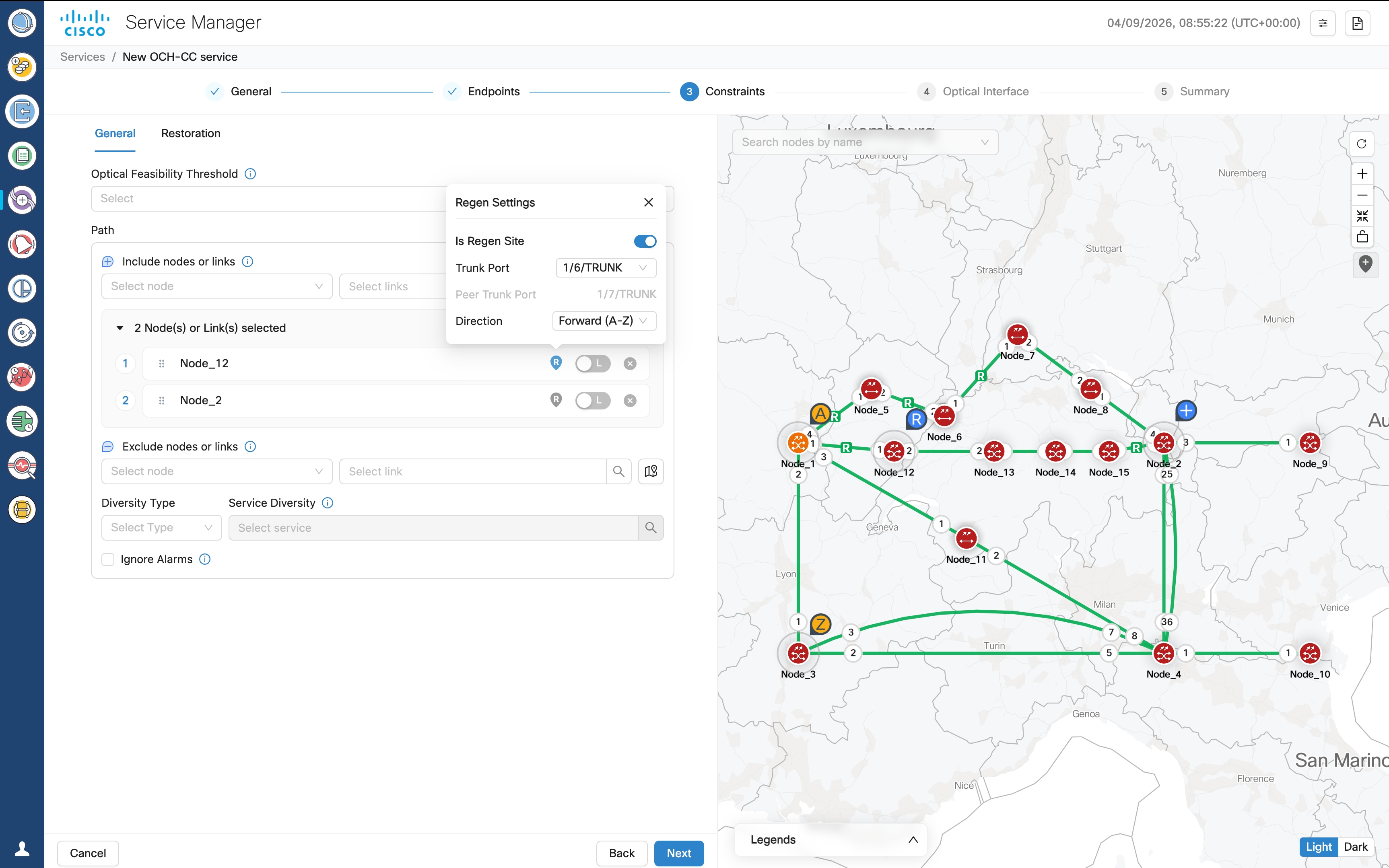
Regen (R) settings icon Allows the control plane to include a regen node present in network to create an end-to-end circuit.
Regen Settings Includes the selected node as a mandatory regen site in the working circuit path. Use the R icon to open this dialog.
  • Include as regen: Enable toggle button include node as regen.

  • Trunk Port: (Optional) Select the trunk port.

  • Direction: (Optional) Select the direction.

Exclude nodes or links select list of nodes & links that has to be excluded by the control plane during path computation.

Diversity Type

Choose the type of service diversity

Node, link, or srlg

Service Diversity Select one or more existing services from the dropdown for the control plane to exclude the resources that the services use during path computation.
Ignore Alarms If true, Service manager ignores unverified alarms present on the path and continues to provision the service.
Note

Optical Feasibility Threshold assesses whether an optical channel is operational after provisioning based on its optical power and Optical Signal-to-Noise Ratio (OSNR). This assessment is represented by colors: RED, GREEN, YELLOW, or NONE.

  1. For regenerated GMPLS OCH-Trail and OCH-CC circuits, add a node in the include constraint list and click the R icon

    Alternatively, you can click the map icon or the blue inverted teardrop icon in the map and select a node from the map.

  2. In the Regen Settings dialog, enable the Is Regen Site toggle button.

  3. You can optionally select a Trunk Port and Direction for the regen site.

  • If the node is selected as general regen node, it appears with a blue inverted teardrop R icon in the topology and REGEN icon in the Detailed service path tab of Circuit Monitoring application.

  • If the node is a normal general node, it appears with a blue inverted teardrop + icon in the topology.

  • For each regen node circuits, when you expand a service in the Service Manager table, segments are displayed and the Regenerated column shows True.

6.

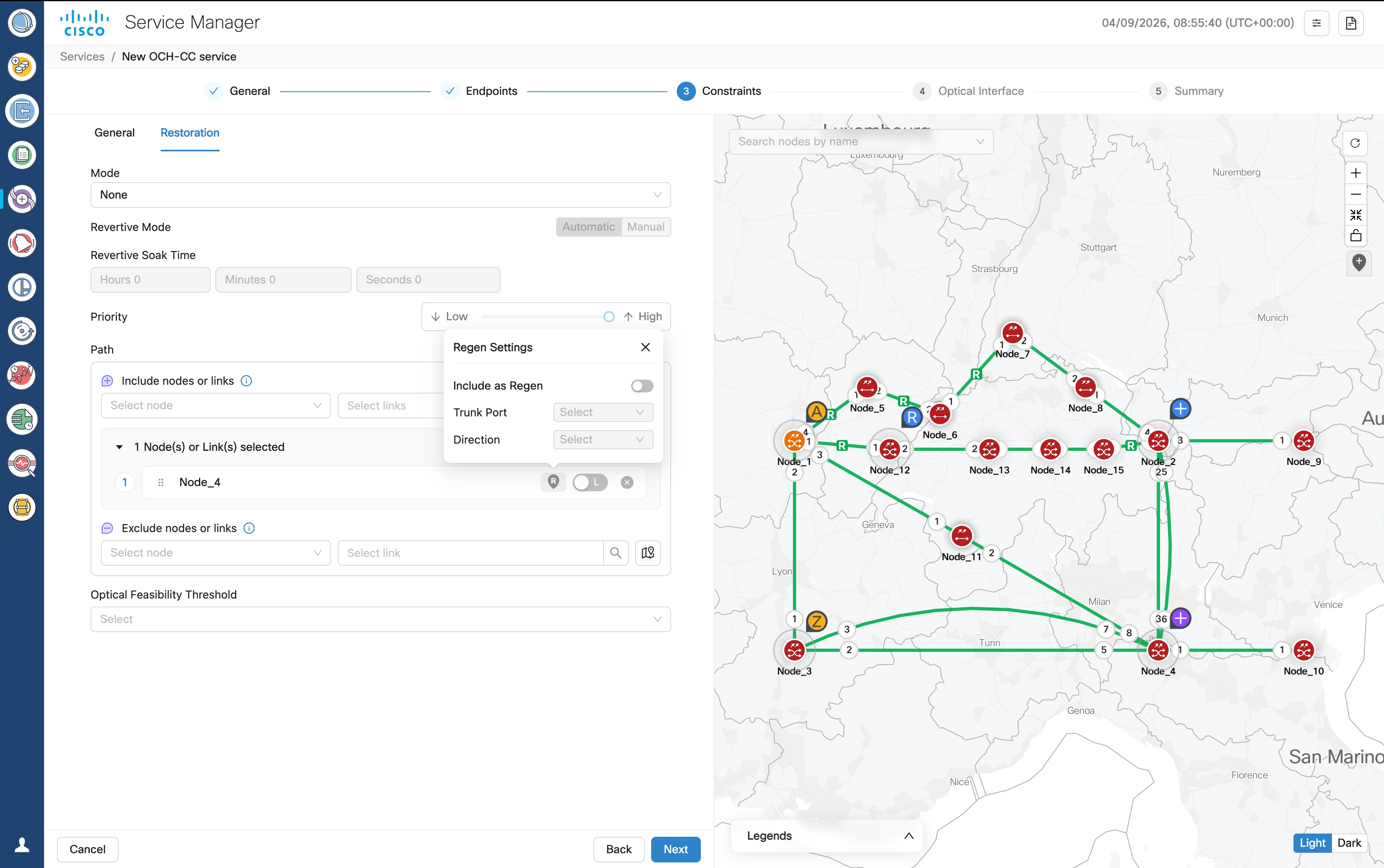
Choose the constraints in the Constraints > Restoration tab, and click Next.

Figure 14. Service Manager > Constraints > Restoration
Table 20. Restoration constraints field descriptions
Field Description Values/restrictions
Mode

None, Enabled, Restorable Alternate, Enabled and Revertive

Revertive Mode Specifies if the revert to main path after it up after a restoration should happen automatically or manually.

Automatic, Manual

Revertive Soak Time Specifies the setup time for the restoration path. This parameter is only applicable for automatic restoration. It is the time in Hours, Minutes and Seconds for the network to switch to the restored path.

Up to 23 hours 59 minutes and 59 seconds

Priority

7—0

0 is the highest priority.

Path
Include nodes or links Select list of nodes & links that has to be included by the control plane during path computation.
Regen (R) settings icon Allows the control plane to include a regen node present in network to create an end-to-end circuit.
Regen Settings Includes the selected node as a mandatory regen site in the working circuit path. Click the R icon to open this dialog.
  • Include as regen: Enable toggle button include node as regen.

  • Trunk Port: (Optional) Select the trunk port.

  • Direction: (Optional) Select the direction.

Exclude nodes or links select list of nodes & links that has to be excluded by the control plane during path computation.
Optical Feasibility Threshold Indicates the optical feasibility of the link to ensure that the link is operational after provisioning.

Select RED, GREEN, YELLOW or ORANGE.

GREEN = mean value

YELLOW = +1 sigma

ORANGE = +2 sigma

RED = +3 sigma

Note

Optical Feasibility Threshold assesses whether an optical channel is operational after provisioning based on its optical power and Optical Signal-to-Noise Ratio (OSNR). This assessment is represented by colors: RED, GREEN, YELLOW, or NONE.

  1. For regenerated GMPLS OCH-Trail and OCH-CC circuits, add a node in the include constraint list and click the R icon

    Alternatively, you can click the map icon or the blue inverted teardrop icon in the map and select a node from the map.

  2. In the Regen Settings dialog, enable the Include as Regen toggle button.

  3. You can optionally select a Trunk Port and Direction for the regen site.

  • If the node is selected as restoration regen node, it appears with a purple inverted teardrop R icon in the topology and REGEN icon in the Detailed service path tab of Circuit Monitoring application after regeneration is completed.

  • If the node is a normal restoration node, it appears with a purple inverted teardrop + icon in the topology.

  • For each regen node circuits, when you expand a service in the Service Manager table, segments are displayed and the Regenerated column shows True.

7.

Choose the optical interface Parameters in the Optical Interface tab, and click Next.

Table 21. Optical interface parameters
Field Description
Wavelength
Central Frequency (THz) Choose a central frequency for the service.
Nyquist Spacing Select Yes to allow channels to share spectral boundaries as long as the center frequency of one channel does not fall within the spectrum of another.
Note

This option is only enabled if central frequency is specified.

Width

Bandwidth used by the circuit

Customer Name The Customer name
Product ID The product ID This is the Product ID of either the pluggable optics for the TXP card with pluggable trunk or the TXP card for the TXP card with fixed trunk.
FEC The FEC depending on the product, for example, CFEC or OFEC depending on the previous selection.
Data Rate The Data rate supported by the selected product.
Baud rate The Baud rate supported by the selected product.
Sub Mode May appear depending on the other selections
Note
  • For OCH-trail,Optical Interface fields are auto populated and non-editable.

  • For regenerated circuits, if a single wavelength is not feasible the first segment is selected and the subsequent segments use different wavelengths.

Clicking next takes you to the Summary tab.

In Release 26.1.1, Topology view in Service Manager reflects the topology screen with a modified Map View Options eye icon. Click the eye icon and then Show Active Service Path to see the current active service path in the network like in Circuit monitoring screen.

Figure 15. Show Active Service Path
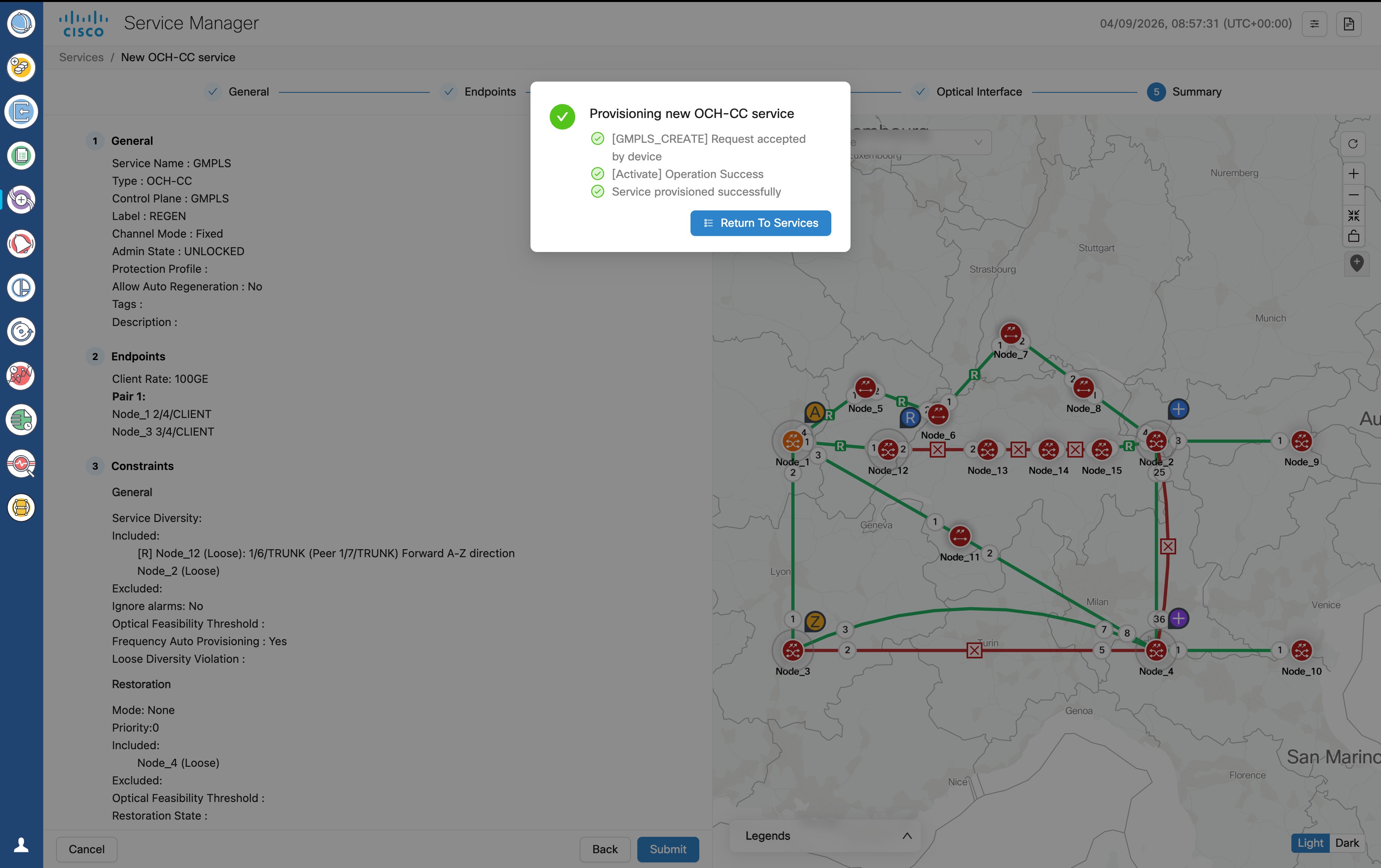
8.

Click Finish to create the circuit.

Figure 16. Service Manager > Summary
9.

Click Return To Services after the circuit is provisioned successfully.

The newly provisioned circuit appears in the Service List table once the provisioning is complete. The Lifecycle State for the new circuit appears as PLANNED initially and later changes to INSTALLED.

For regenerated GMPLS OCH-Trail and OCH-CC circuits, the Regenerated column shows true. Circuit details display the service in segments, and regen sites are identified with R in the circuit view.

The create and manage GMPLS services task is complete.

These are some errors you may come across when trying to provision a GMPLS circuit. Use the information to troubleshoot GMPLS errors.

Table 22. Details
Error Description
No wavelength available on path

The optical path in the node terminates on a port not matching the requested protection mode.

Reroute Failed

The requested action can not be executed as the selected circuit is already in rolled state

Optical Validation The partial path evaluated during route selection is outside the receiver OSNR threshold.
No client port available on trunk port

No available Client port matching the request constraints is found connected to the TXP Trunk port

No available optical path in node No wavelength is available on the optical path.

This table summarizes the additional supported circuit provisioning options for the NCS 2000 100G-LC-C and 400G-XP-LC cards across GMPLS configurations.

Table 23. Supported circuit provisioning options for 100G-LC-C/100G-ME-C and 400G-XP-LC cards

Configuration

OCH-CC

OCH-Trail

OCH-NC

NCS2000 100G-LC-C/100G-ME-C standalone Yes Yes Yes
NCS2000 100G-LC-C/100G-ME-C with peered ONS 15454 10x10G-LC Yes Yes Yes
NCS2000 400G-XP-LC with peered ONS 15454 10x10G-LC Yes Yes Yes
10X10G with MPO cable connected to 400G-XP-LC No Yes Yes

Manage GMPLS services

Use this procedure to create and manage circuits.

These are some errors you may come across when trying to provision a GMPLS circuit. Use the information to troubleshoot GMPLS errors.

Table 24. Details
Error Description
No wavelength available on path

The optical path in the node terminates on a port not matching the requested protection mode.

Reroute Failed

The requested action can not be executed as the selected circuit is already in rolled state

Optical Validation The partial path evaluated during route selection is outside the receiver OSNR threshold.
No client port available on trunk port

No available Client port matching the request constraints is found connected to the TXP Trunk port

No available optical path in node No wavelength is available on the optical path.

Before you begin

Table 25. Supported transponder cards and modes

Card

Modes Supported

NCS1K4-2-QDD-C-K9

MXP-SLICE: 200G, 300G, 400G trunk and 100G and OTU4 client

NCS1K4-QXP-K9

MXP-SLICE: 400G trunk with 400G and 100G client

NCS1K4-OTN-XP

MXP: 4x100G

TXP: 400G

400G trunk with 100G, 10G and OTU2 clients

NCS1K14-2.4T-X-K9

MXP-SLICE: 400G, 600G, 800G, 1T, 1.2T trunk with 100G and 400G clients

NCS1K4-1.2T-K9

MXP: 100G, 200G, 300G, 400G trunk with 100G and OTU4 client

MXP-SLICE: 2 trunks with 100G, 200G, 300G, 400G bandwidth and 100G and OTU4 client

Supports SD-FEC-27 and SD-FEC-15

NCS2K-400G-XP-LC

MXP: 400G trunk and 100g, 10G clients

FEC Modes: SD_FEC_15_DE_OFF, SD_FEC_15_DE_ON, SD_FEC_25_DE_OFF, SD_FEC_25_DE_ON

MXP with backplane connection to 15454-M-10X10G-LC with slice 2 configured as OPM-PEER-ODU2 or OPM-PEER-ODU2E

REGEN: 100G and 200G trunk regeneration for GMPLS OCH-Trail and OCH-CC circuits

NCS2K-200G-CK-C

TXP-100G: 100G trunk and client

FEC Modes: HG_FEC_7, SD_FEC_20, SD_FEC_25_DE_OFF, SD_FEC_25_DE_ON

RGN-100G: 100G trunk regeneration for GMPLS OCH-Trail and OCH-CC circuits

15454-M-10X10G-LC

MXP 10x10G (with backplane connection to NCS2k-200G-CK-C/15454-M-100G-LC-C/15454-M-100G-ME-C) 100G trunk and 10G, OTU2, OTU2e, and OC192/STM64 clients

15454-M-100G-LC-C and 15454-M-100G-ME-C

  • 10x10G client card

  • 100GE TXP mode: 100G trunk and 100GE/OTU4 clients

Note

From release 25.1.1, Cisco Optical Network Controller supports OCH-CC circuits between client ports that have the same client type and the same equipment type at both endpoints.

Note

From release 26.1.1, Cisco Optical Network Controller discovers the ODU connections and builds the end-to-end protected or unprotected OTN services. Cisco Optical Network Controller automatically discovers the full OTN service when the OCH-Trail for GMPLS circuits are discovered. Additional OTN services can be added via CTC.

In release 26.1.1, OTN services are supported in the OTN-XC card mode of the NCS2K-400G-XP-LC line card only.

Follow these steps to create and manage GMPLS services:

Procedure

1.

Select a service and click Edit to edit the circuit.

  1. Go to Constraints > General and update the constraints. Click Reroute after updating constraints to reroute the circuit.

    A status pop-up appears showing the progress of the reroute process.

    For regenerated GMPLS OCH-Trail and OCH-CC circuits, you can edit regen constraints and reroute the circuit to apply the updated regen path.

  2. Go to Constraints > Restoration and update the constraints.

    You can update regen constraints for the restoration path of a regenerated circuit.

  3. Click Upgrade Restored to make a restored circuit path the main circuit path.

  4. Click Revert Restored to revert to the main path when Revertive mode is Manual.

    Clear unverified alarms from COSM before performing this step.

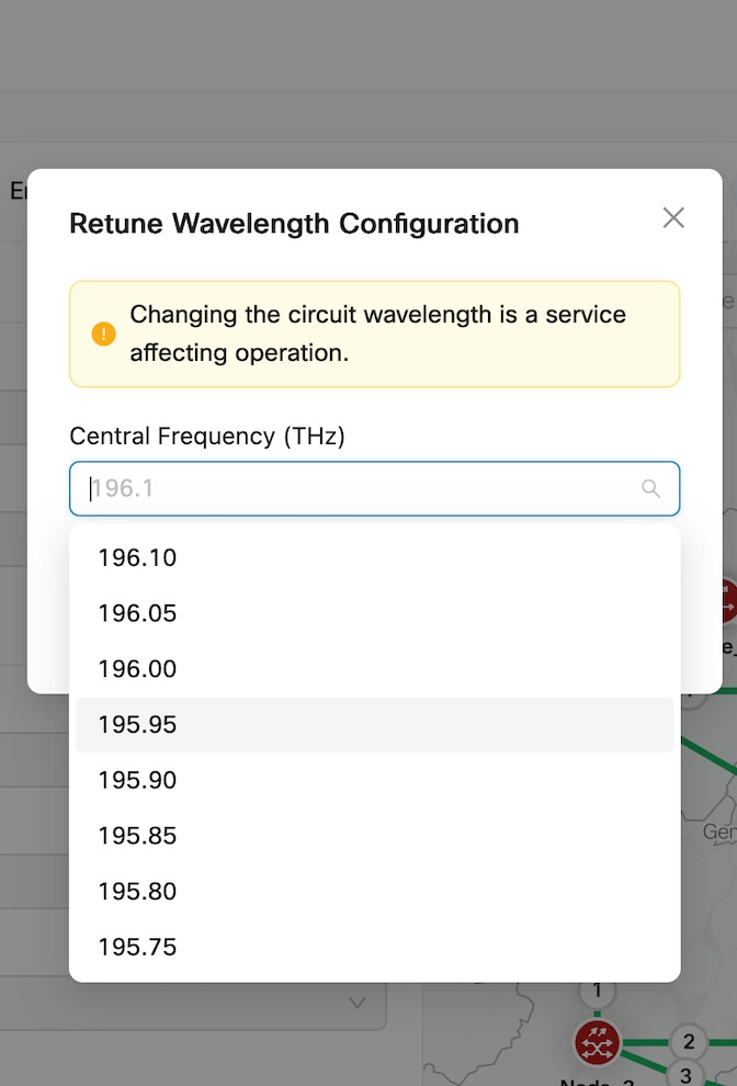
  5. Go to Optical Interface, change the wavelength parameters, and click Retune to change the wavelength.

    Figure 17. Service Manager > Optical Interface > Retune
    screenshot
Note

These options are available only for GMPLS Trails and OCH-NC circuits.

For OCH-CC circuits you can edit only the name and Admin state.

2.

Click Delete to delete a selected service from the table.

The Lifecycle state changes to DELETION_IN_PROGRESS and then the service is removed from the service list when deletion is complete.

Note

The service may go to PARTIAL state during the deletion. This is a transient state before the circuit is deleted.

The status may change to DELETION_FAILED if the operation fails. Delete operation may fail in the following scenarios:

Table 26. Deletion failure scenarios

Reason

Troubleshooting

Cross connect was deleted outside Cisco Optical Network Controller

  • Retry deleting the service

  • Use the resync option in Service Manager and try again

  • Perform an full network resync and try again

  • Try deleting the service from Cisco Transport Controller

Node busy

Wait for any operations on the node to complete and retry

Node disconnected

Reestablish connectivity to the node

COSM lost connection to the subtended device

Reestablish COSM connectivity to the device and try again

3.

Click + icon after selecting any service to expand the service and view its carriers.

Carriers can be of either single or multiple service types. Multiple carriers can have the same Endpoints over different channels.

The create and manage GMPLS services task is complete.

This table summarizes the additional supported circuit provisioning options for the NCS 2000 100G-LC-C and 400G-XP-LC cards across GMPLS configurations.

Table 27. Supported circuit provisioning options for 100G-LC-C/100G-ME-C and 400G-XP-LC cards

Configuration

OCH-CC

OCH-Trail

OCH-NC

NCS2000 100G-LC-C/100G-ME-C standalone Yes Yes Yes
NCS2000 100G-LC-C/100G-ME-C with peered ONS 15454 10x10G-LC Yes Yes Yes
NCS2000 400G-XP-LC with peered ONS 15454 10x10G-LC Yes Yes Yes
10X10G with MPO cable connected to 400G-XP-LC No Yes Yes