Cisco Optical Network Controller Configuration Guide, Releases 26.x.x

PDF

Cisco Optical Network Controller Configuration Guide, Releases 26.x.x

Cisco Optical Network Controller links

Want to summarize with AI?

Log in

This section explains Cisco Optical Network Controller links, including link views, action options, and ASE service handling. Use it to understand link information before managing optical services.


Before you begin

Follow these steps to use the links application:

Procedure

1.

Open the Links app from the sidebar.

2.

Edit Link Attributes.

  1. Select a link in the OMS or Undiscovered OMS tab.

    Note

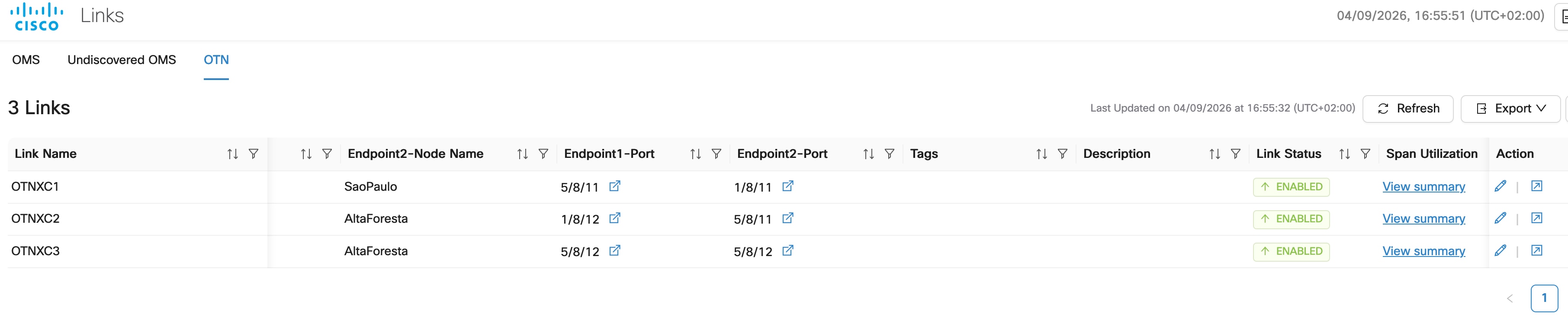
    From release 26.1.1, for OTN networks, the Links application displays OMS Links and OTN Links attributes only.

  2. Click the edit (pencil) icon in the Action column.

  3. Modify the Link Name, Tags, or Description.

  4. Click Save to apply the changes.

3.

View the Circuit Monitoring workspace for a link.

  1. Select a link in the OMS or Undiscovered OMS tab.

    Note

    From release 26.1.1, for OTN networks, the Links application displays OMS Links and OTN Links attributes only.

  2. Click the circuit monitoring icon in the Action column.

The Circuit Monitoring page opens, filtered to display circuits related to the selected link.
4.

View PM History for a link.

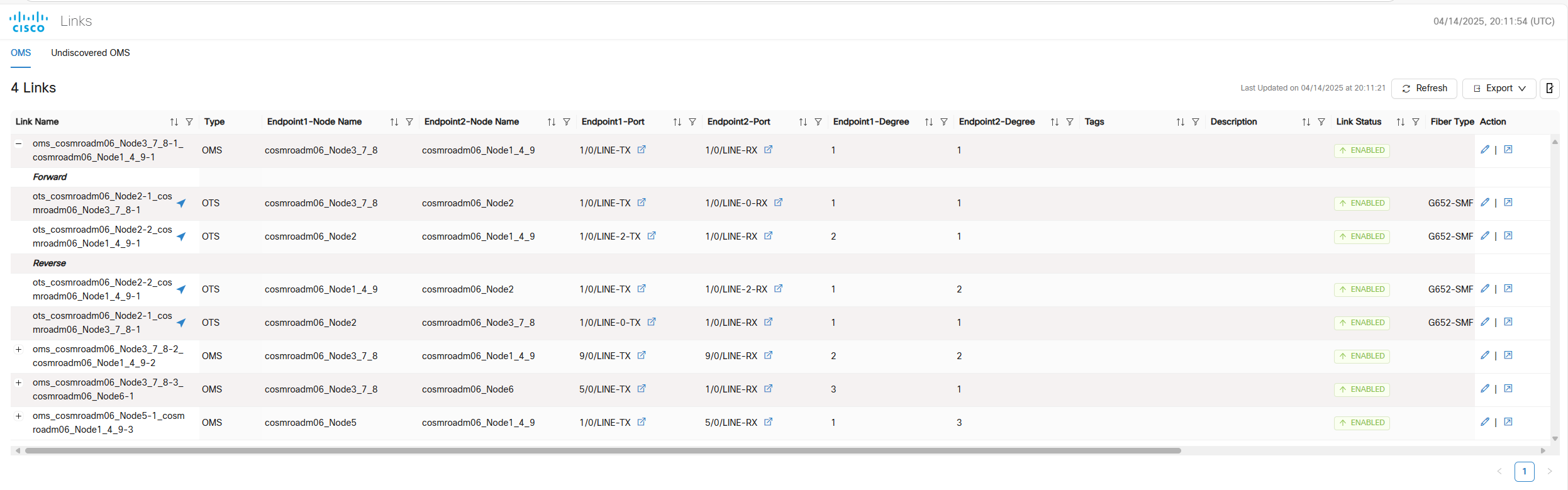
  1. In the OMS tab, expand an OMS link to view its OTS links.

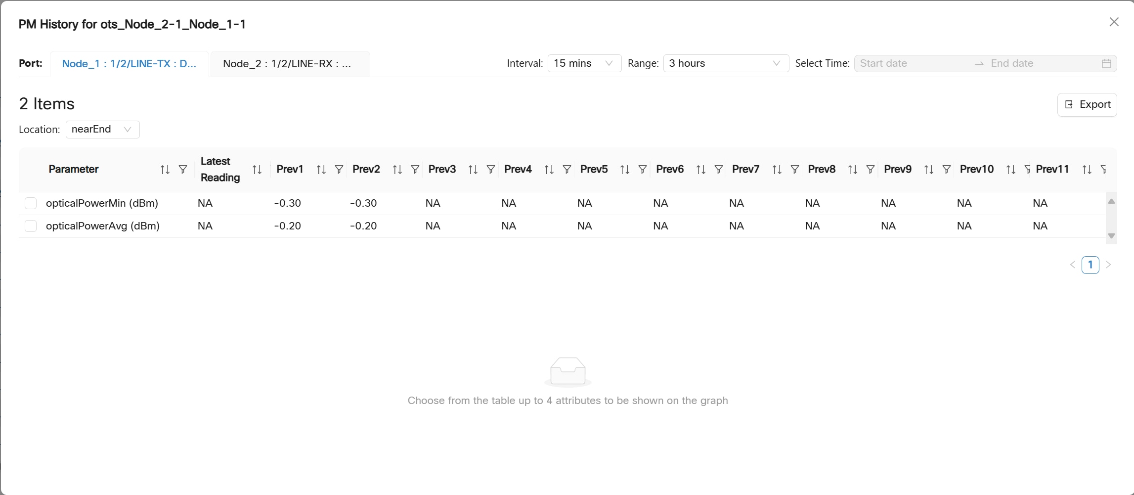
  2. Click the arrow icon next to an OTS link to view its PM history.

    Figure 3. Links App
    screenshot of links app
  3. Select an interval and predefined time range or choose a custom range.

    The PM history table is displayed.
  4. Select up to 4 parameters to view on the graph.

5.

Cross-Launch to OCM/OTDR in Cisco Optical Site Manager.

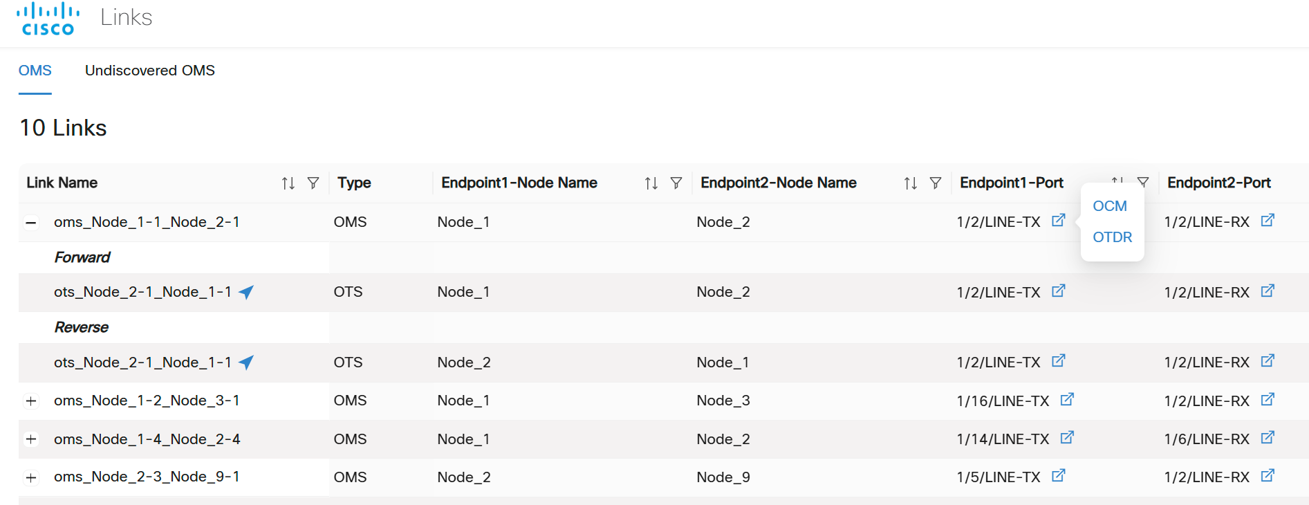
  1. In the OMS tab, expand an OMS link to view its OTS links.

  2. Click the cross-launch icon in the Endpoint1-Port or Endpoint2-Port.

    Figure 4. Links App
    screenshot of links app
  3. Click OCM or OTDR to cross-launch the OCM or OTDR tab in Cisco Optical Site Manager for the selected endpoint.

    If OTDR is not supported, it navigates to alarms.

6.

Export Links data.

  1. Click Export.

  2. (Optional) Select Table View and click Export to export and download the data currently displayed in the table.

  3. Select Network Linksto export all network links.

  4. Click Generate.

  5. After the file is generated, click Export to download the XLS file.

Note

After expanding links, wait for up to 60 seconds for the Total Transmit Power Tx(dBm) and Total Receiver Power Rx(dBm) values to be fetched. If you export or Generate a full report before all the values are fetched, the report contains only the power values for the links for which the values were fetched.


Before you begin

  • Configure the ASE channels on the submarine nodes by using XR CLI before onboarding the nodes in Cisco Optical Network Controller. For more details on configuring SLTE using XR CLI, see Sub-sea Configuration.

  • Ensure that the SLTE nodes and their links are already discovered in Cisco Optical Network Controller.

Follow these steps to change an SLTE link deployment type.

Procedure

1.

Click Links and then click the OMS tab.

2.

Locate the required OMS link and expand the entry to show the underlying OTS links.

The Deployment Type can be configured on the OTS link.

3.

For the required OTS link, click Edit action.

4.

In the Edit Link dialog box, select select Submarine or Terrestrial from the Deployment Type drop-down list.

Select Submarine when the link is part of an SLTE deployment and the discovered type must be corrected.

5.

Save the change.

Cisco Optical Network Controller updates the OTS link deployment type.

6.

Click Refresh and verify the updated deployment type in the link list.


Convert SLTE ASE channel to user channel

Use this procedure to convert SLTE ASE channel to user channel in Cisco Optical Network Controller. Complete this task when you need to configure, verify, or manage the related network operation.

The SLTE ASE tab in Service Manager displays discovered ASE services with their endpoint, frequency, and bandwidth based on SLTE configuration.

During this upgrade, constraints used by other service types are not applicable to the SLTE ASE workflow.

  • The configuration is rejected in these cases:

  • The ASE channel central frequency and channel width exactly match the user-provided central frequency and channel width for the user channel. Remove the hardware module for the ASE channel and configure the end-to-end circuit from Cisco Optical Network Controller.

  • The user channel extends beyond the ASE channel into empty spectrum. Remove the ASE channel and configure an end-to-end circuit from Cisco Optical Network Controller.

  • The user channel has a narrower width than the ASE channel but uses the same central frequency. Remove the ASE channel and configure the end-to-end circuit from Cisco Optical Network Controller.

  • Cisco Optical Network Controller provisions the required user circuit when a new user channel on the same add/drop port overlaps an existing user channel, provided that only frequency slices overlap and the payloads do not overlap.

  • When a submarine channel is created, CPCE performs no optical validation except for central frequency and channel width.

Before you begin

Ensure that the SLTE nodes are onboarded and that the required ASE services are already discovered.

Follow these steps to convert an SLTE ASE channel to a user channel.

Procedure

1.

Click Service Manager and then click the SLTE ASE tab.

The list of discovered ASE services is displayed.

2.

Select the endpoint of the actual user channel service that you want to convert.

Review the endpoint, frequency, and bandwidth columns to confirm that you selected the correct ASE channel.

3.

Click Upgrade and select a service.

4.

Complete the steps in the CPCE service endpoints and operations task to finish converting the selected ASE channel to a user channel.

The selected ASE channel is converted to a user channel in Cisco Optical Network Controller, and the new user service is shown in Service Manager.

Note

Deleting the user channel restores the ASE channel, ensuring the spectrum is filled.