Use this procedure to manage alarms. The Alarms screen displays all the alarm details for each node based on the severity level.
Use this procedure to manage alarms in Cisco Optical Network Controller. Complete this task when you need to configure, verify, or manage the related network operation.
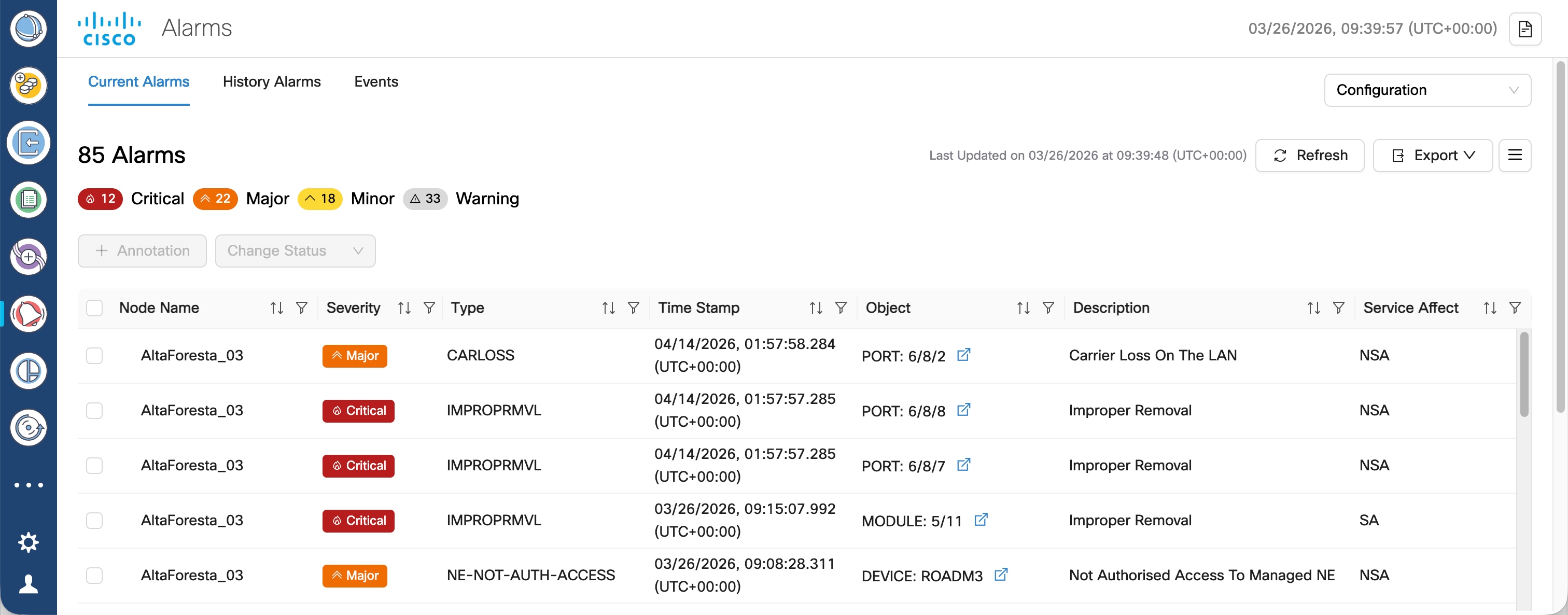
The Alarms screen displays all the alarm details for each node based on the severity level. You can view both the active alarms and the previously active alarms in this screen.
Figure 1. Alarms
For viewing the active alarms using AlarmsCurrent Alarms tab and the other for previous alarms using HistoryHistory Alarms tab.
Indicates whether the alarm is service affecting or non-service affecting.
NSA, SA
Location
The physical location of the affected equipment.
Direction
The direction of the alarm.
Receive,
User Tag
User-defined tags for categorizing and filtering alarms.
Note
User tags propagate from parent to child components of a chassis by default. A user tag on a child component overrides the inherited tag from its parent.
User Tag information comes from Cisco Optical Site Manager. See User Tags.
User tags are not supported on system-level and device alarms.
User tags can apply CLLI (Common Language Location Identifier), a standardized 11-character code that uniquely identifies geographic locations and equipment for network sites, network support sites, and customer locations.
Custom tags/labels
User Notes
User-added notes or comments related to the alarm.
Free-form text
Acknowledge
Indicates whether the alarm has been acknowledged.
Acknowledged, Unacknowledged
UUID
Unique Universal Identifier for the alarm.
UUID string
Correlation Type
The type of correlation applied to the alarm.
Network Level, Node Level
Note
You can filter the alarms table based on the fields. You can filter alarms to show only network-level or node-level correlated alarms.
Use this procedure to view events in the alarms application in Cisco Optical Network Controller. Complete this task when you need to configure, verify, or manage the related network operation.
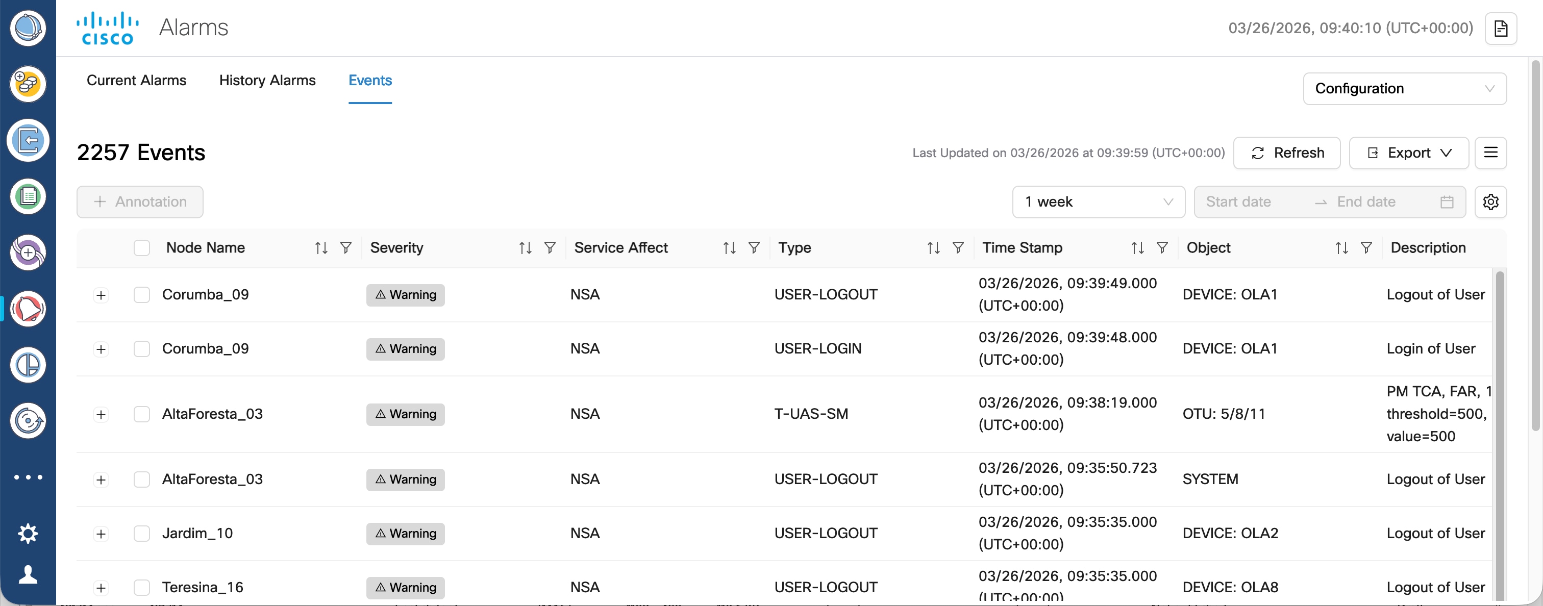
The Events tab displays events tracked separately from current alarms, such as user login, logout activity, and performance monitoring notifications. Unlike Current Alarms, events are informational entries and do not support acknowledge or unacknowledge actions.
Figure 2. Events tab in Alarms application
Before you begin
Ensure that you are logged in to Cisco Optical Network Controller.
Follow these steps to view and manage events in Alarms application.
Procedure
Click Alarms in the left pane.
Click the Events tab.
The table shows the latest event for each node. Event types include user login, user logout, and performance monitoring notifications. For details about the table fields, see Table 1.
To filter events by timeframe:
Select Custom Date Range and specify the start and end dates to filter the events for the selected period.
By default, 1 week is selected to display events from the past 7 days.
(Optional) Click the settings icon and enter the number of weeks in the Weeks to retain events data to define the default event data retention period.
Valid range: 1 week to 12 weeks
Note
Transient alarms are also displayed under the Events tab. During new device onboarding or resynchronization, the client receives updates only for transient alarm differences within the configured retention period. If the retention period is increased and device resynchronization is triggered, older historical transient alarms that fall within the expanded retention period but are not present in CONC may be sent as Raised notifications. This can cause an expected temporary increase in notifications.
To add user notes to events, complete these steps.
Select an alarm or multiple alarms and click Annotation.
In the Add User Notes dialog box, enter the note text and click Add.
Optional: Use the sort and filter controls in the column headers to find specific events.
Click the + icon next to an event entry to view the event history and the associated user notes.
The expanded view shows the recorded event status entries for the selected node and any user notes that were added to that event.
Click the hamburger icon to show or hide columns.
You can review events separately from current alarms and use the available controls to filter, inspect, annotate, refresh, and export the event data.
Network level alarm correlation
Network level alarm correlation is a Cisco Optical Network Controller capability that
supports the related optical network management workflow,
provides context for configuration, monitoring, or troubleshooting tasks, and
helps operators understand how the feature behaves before they use it.
Network level alarm correlation details
The Network Level Alarm Correlation (NLAC) in Cisco Optical Network Controller is designed to reduce alarm noise and improve troubleshooting efficiency by correlating related alarms and suppressing redundant ones. When a root cause alarm is identified at the network level, NLAC suppresses all subtending alarms associated with that root cause, providing a clearer view of the network's health and focusing operator attention on the most critical issues.
Note
The node or site level correlation is done by Cisco Optical Site Manager and the network level correlation is done by Cisco Optical Network Controller.
From Cisco Optical Network Controller release 25.1.1, NLAC works over a a single OMS domain. Alarm correlation does not cover alarms across multiple OMS domains.
Alarm Hierarchy Display
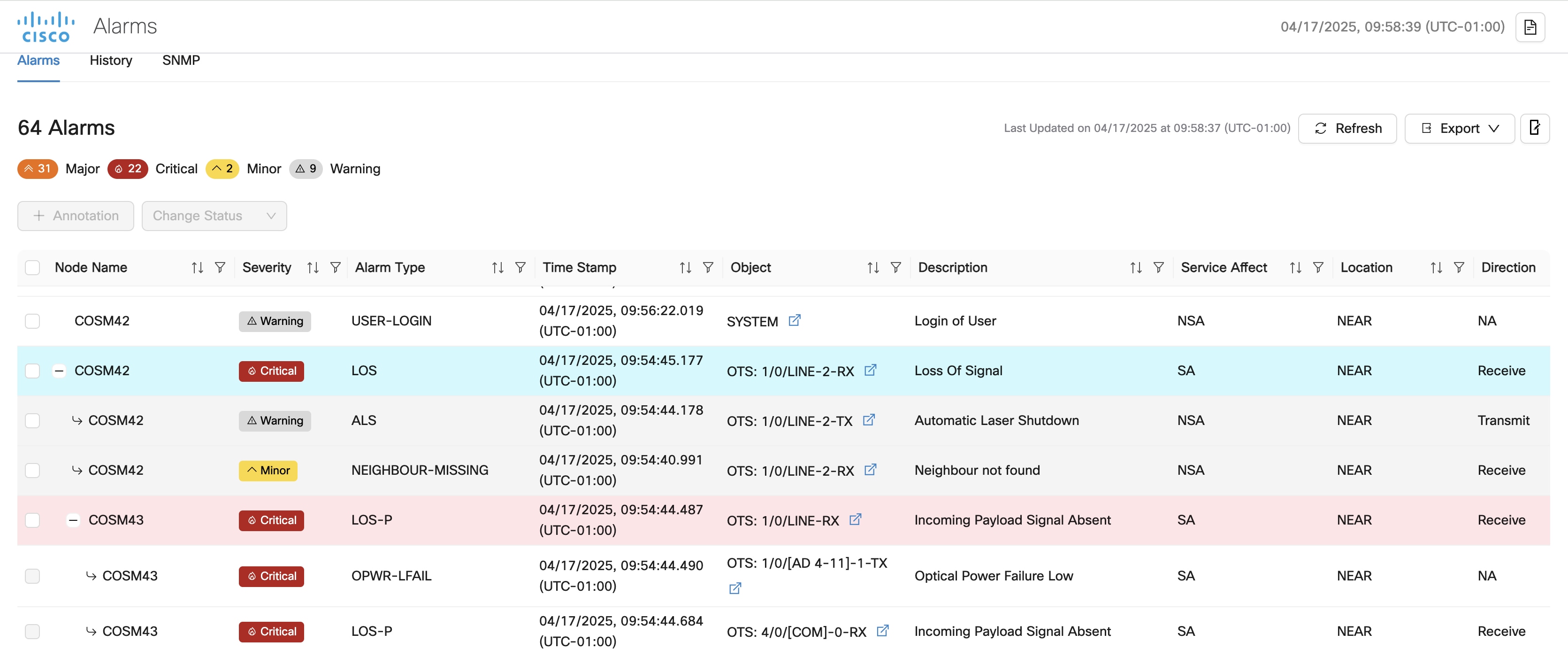
The alarm display presents a hierarchical view of correlated alarms.
The network level root cause alarm is displayed at the top level and is higlighted in blue color.
Subtending alarms are displayed as children of the root cause alarm, accessible by clicking a plus (+) icon.
Site-level correlated alarms are displayed at the second level of the hierarchy.
The site level root cause alarm is in the second level and is higlighted in red color.
Alarms correlated at the node level cannot be acknowledged or have user notes added in Cisco Optical Network Controller.
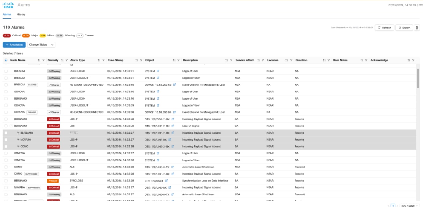
Figure 3. Alarms History
Alarm Correlation
Alarm correlation takes place at the network level and at the site level. Network level alarm correlation is performed by Cisco Optical Network Controller. Site level correlation is performed by COSM.
When a LOS alarm on Line is identified as the root cause, it suppresses the following alarms. This correlation is performed by Cisco Optical Network Controller. Site level correlation is independent of network level correlation. You can see site level root cause alarms and suppressed alarms without a network level root cause alarm.
Table 2. Alarms suppressed by LOS on line
Alarm
Object Type
LOS-P
LINE
LOS-P
OSC
ALS
LINE
PARTIAL-TOPOLOGY
LINE
APC-BLOCKED
LINE
NEIGHBOUR-MISSING
LINE
LOS-O
LINE
LOS-O
OSC
Note
Alarms that are the root cause display the + icon next to them and when you click this icon it displays all the suppressed alarms.
Links and nodes that have the suppressed alarms are not included in the summary and list of alarms in Workspaces, Service Assurance and Topology.
A link with suppressed alarms does not consider a suppressed alarm as its highest severity alarm.
You cannot acknowledge alarms that Cisco Optical Site Manager correlates from Cisco Optical Network Controller
Filters on the alarm table do not work for supppressed alarms. You cannot see suppressed alarms when you use a filter.
Purpose of Using NLAC
When a fiber cut occurs, it triggers a Loss of Continuity (LOC) alarm, which is then correlated with other Loss of Signal-Payload (LOS-P) alarms in the circuit. The root cause alarm, typically the LOC, suppresses other alarms, ensuring that subsequent LOS-P alarms depend on the LOC rather than the Automatic Laser Shutdown (ALS) alarms.
Benefits of Using NLAC
The benefits of using NLAC are:
Reduced Alarm Noise: NLAC significantly reduces the number of alarms displayed, making it easier for operators to identify and address critical issues.
Quick Fault Isolation: Helps in quickly identifying and isolating the root cause of network issues.
Improved Network Reliability: By correlating alarms effectively, it enhances the overall reliability and performance of the network.
Simplified Troubleshooting: Makes it easier for network administrators to troubleshoot and resolve issues by providing clear alarm correlations.
Scenarios for Using NLAC
There are multiple scenarios which specify how NLAC is used, some of them are:
Unidirectional Fiber Cut:
Correlation Mechanism: LOS to LOS-P: Forward direction
Correlation Mechanism: ALS to LOS-P: Reverse direction.
Multiple LOS in Forward Direction: For multiple LOS scenarios both in upstream and downstream circuits.
Bidirectional Fiber Cut:
Note
In the bidirectional scenario, we have LOS and LOS-P correlations in both the directions. In addition, we will also have ALS to LOS-P correlation up to the port where we have the LOS. In this situation, LOS will correlate to all LOS-P downstream.
Correlation Mechanism: LOS to LOS-P: Forward and reverse direction.
Correlation Mechanism: ALS to LOS-P: Reverse direction.
Multiple LOS in Forward or Reverse Direction: For multiple LOS scenarios both in upstream and downstream circuits.
New LOS in Reverse direction: For new loss in the downstream circuits.
NLAC LOC and LOS-P Alarms
These alarms can be viewed in the Alarms and Workspaces applications for each node.
Figure 4. LOS and LOS-P Correlation
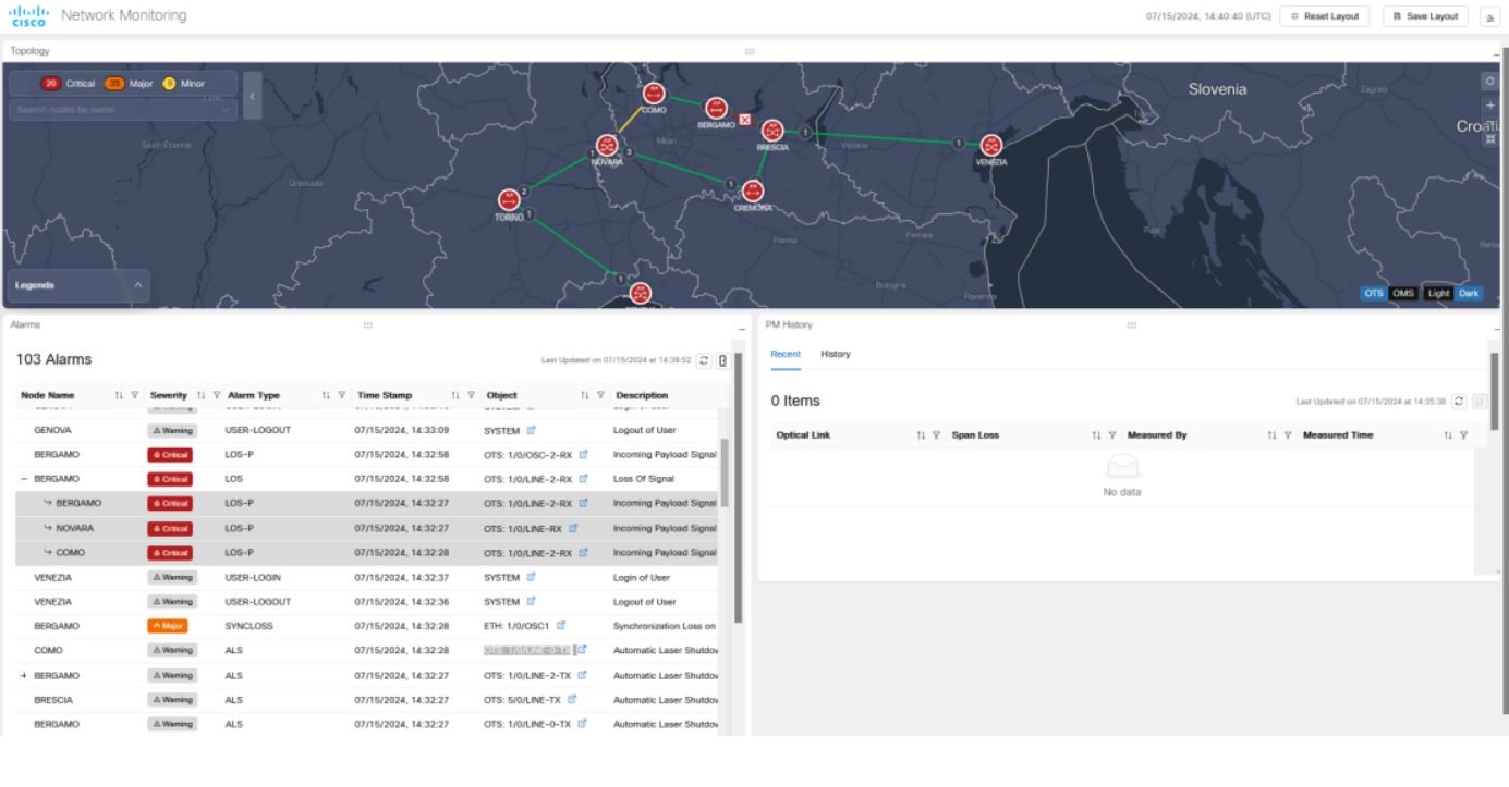
Figure 5. LOS and LOS-P Correlation in Network Monitoring
Acknowledged alarm mute
Acknowledged alarm mute is a Cisco Optical Network Controller capability that
supports the related optical network management workflow,
provides context for configuration, monitoring, or troubleshooting tasks, and
helps operators understand how the feature behaves before they use it.
Acknowledged alarm mute details
It is now possible to mute low priority alarms and disable them from appearing in the Topology, Service Assurance, Network Monitoring, and Circuit Monitoring screens.
Purpose of Acknowledged Alarm Mute
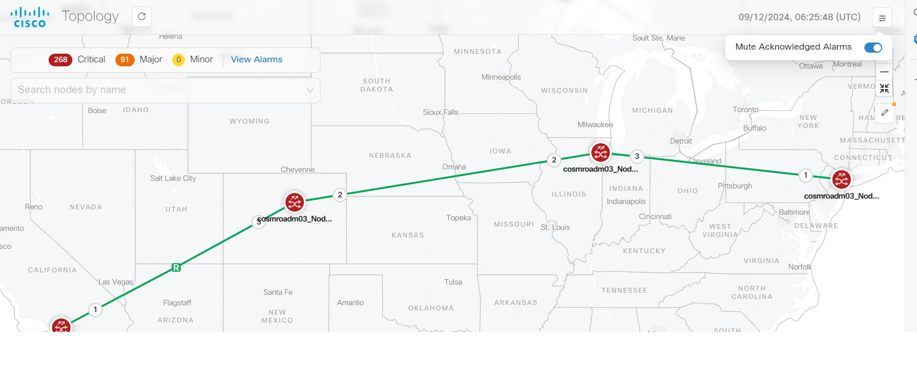
By enabling the Mute Acknowledged Alarms toggle switch option to True, you can hide the acknowledged alarms and disable them from appearing in the Workspaces, Service Assurance and Topology summaries and alarms lists, even if they are available in the Alarms application.
Benefits of Using Acknowledged Alarm Mute Option
The acknowledged alarm mute option allows you to have only the selected alarms appearing in the screen, instead of the entire set of all the acknowledged alarms. This helps in reducing unwanted clutter on the screen. As all the unnecessary acknowledged alarms that you do not want to be displayed can be hidden using this option.
Muting the Acknowledged Alarms
To mute the alarms on the screen:
Acknowledge the alarm from the Alarm screen.
Toggle the Mute Acknowledged Alarms button to True.
Note
Once an alarm is acknowledged, and the toggle switch button is set to True, the alarm will no longer be visible in the Topology, Service Assurance, Network Monitoring, and Circuit Monitoring screens.
Node and link colors take the color of the highest severity unacknowledged alarms on each node and link.
Notifications for Acknowledged Alarm Mute
Whenever the alarms are acknowledged and muted, related notifications are sent on the screen. The scenarios for the notifications are as given:
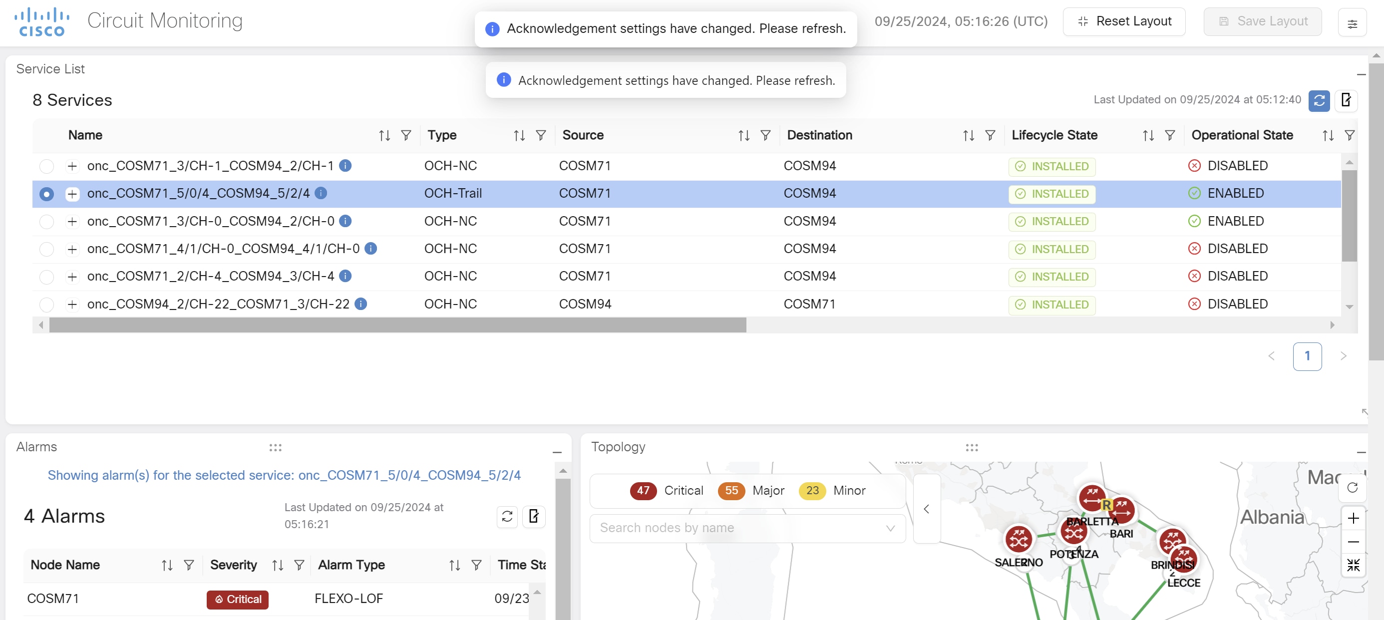
Notifications are sent to inform all users of any toggle changes, prompting them to refresh their pages to see updates.
When an alarm is acknowledged and the Mute Acknowledged Alarms button is set to True, notifications are sent updating device and link summaries. This occurs only if 10 or fewer alarms are acknowledged.
Whenever a new alarm is raised, cleared or updated new notifications are sent. But when an alarm is cleared, its acknowledgement status is lost due to which you must reset it back again.
Acknowledged alarms are excluded from the Topology, Service Assurance, Network Monitoring and Circuit Monitoring applications when the Mute Acknowledged Alarms toggle switch is set to True.
Note
A restriction is placed on the number of alarms that can be acknowledged at once. This is to ensure a single notification is sent, prompting users to refresh their pages.
When you select the circuit, the respective alarms in the circuit that are not acknowledged are displayed when the Mute Acknowledged Alarms is set to ON. In the Topology screen you will be able to view the count of such alarms. In the Circuit Monitoring screen you will be able to see these alarm details.
The Mute Acknowledged Alarms option can be used in the Network Monitoring application as well.
Only the admin user or the supervisor with admin access can mute the acknowledged alarms using the Mute Acknowledged Alarms toggle switch.
Figure 6. Mute Acknowledged Alarms in Topology
Figure 7. Mute Acknowledged Alarms in Circuit Monitoring
SNMP traps and alarm filters
SNMP traps and alarm filters is a Cisco Optical Network Controller capability that
supports the related optical network management workflow,
provides context for configuration, monitoring, or troubleshooting tasks, and
helps operators understand how the feature behaves before they use it.
SNMP traps and alarm filters details
The SNMP tab under the alarms app, allows Cisco Optical Network Controller to send alarm traps to external SNMP managers. This enables integration with external monitoring systems and provides a mechanism for forwarding alarm information. Cisco Optical Network Controller supports both SNMP v2c and v3.
Alarms and Events
An event is a distinct incident that occurs at a specific point in time, such as a port status change, or a device becoming unreachable. Events can indicate an error, failure, or exceptional condition in the network. Events can also indicate the clearing of those errors, failures, or conditions. Events have associated severities which you can be adjusted.
An alarm is a response to one or more related events. Only certain events generate alarms. Alarms have a state (cleared or not cleared) and a severity (Critical, Major, Minor, and so forth). An alarm inherits the severity of its most recent event. Alarms remain open until a clearing event is generated (or if the alarm is manually cleared).
Note
Cisco Optical Network Controller does not support notification replay. Hierarchical controllers miss notifications when Cisco Optical Network Controller is down or not reachable.
SNMP manager configuration
Supports configuration of up to four SNMP managers.
Supports both UDP and TCP protocols for trap transmission.
Allows configuration of SNMP v2c and v3 managers.
Alarm filtering
Provides detailed filter configuration options to control which alarms are sent to each SNMP manager.
Supports filtering by alarm severity (Critical, Major, Minor, Warning).
Supports filtering by alarm type (e.g., Cisco Optical Network Controller generated alarms, circuit alarms, device alarms, restoration alarms).
Allows exclusion of specific alarm types to avoid overwhelming OSS systems.
Provides separate filtering for transient (events) and non-transient (alarms) conditions.
Set the host name
The host name is used to identify the Cisco Optical Network Controller server sending the SNMP traps.
The host name is used to identify the Cisco Optical Network Controller server sending the SNMP traps.
Before you begin
There is a character limit of 25 characters for the host name.
Only alphanumeric characters, underscores, and hyphens are allowed in the host name. Spaces are not allowed.
If you do not set a host name, the default value CONC is used.
Follow these steps to set the host name:
Procedure
Click Set/Edit Host Name.
Enter the desired hostname.
Click Save.
Click View Engine id
Note
The Engine ID remains the same for all SNMP managers.
The Engine ID is displayed and can be copied for use in the receiver application.
The set the host name task is complete.
Configure SNMP managers
Add an SNMP manager and configure the alarm filters used to send traps.
Cisco Optical Network Controller converts alarms and events that match the configured filters into traps and sends them to the SNMP manager using CISCO-EPM-NOTIFICATION-MIB. For more information, see MIB Definition For Cisco Optical Network Controller.
Procedure
Navigate to Alarms > SNMP.
Create an SNMP manager.
Enter the Server Name and IP Address.
Cisco Optical Network Controller supports only IPv4.
Enter the Port Number, and choose the SNMP Version.
If you choose the SNMP Version as v2c, enter the Community settings as required.
If you choose the SNMP Version as v3, enter the Username, Mode, Auth. Type, Auth. Password, Confirm Auth. Password, Privacy Type, Privacy Password, and Confirm Privacy Password.
Choose the Notification Type, TCP or UDP.
Choose the Trap Configuration, Send all traps or Set custom trap filters.
If you choose AND, you get notifications for only the alarms that match both the severity selection and type selection.
If you choose OR, you get notifications for the alarms that match either the severity selection or type selection.
Use the transfer list to exclude specific alarms. Use filters in the table to find the specific alarms you want to exclude.
Click Apply.
The custom trap filter for the SNMP manager is created.
The configure SNMP managers task is complete.
If traps are not being received, verify the SNMP manager configuration, including the IP address, port, protocol, and security settings.
Check the alarm filters to ensure that the desired alarms are not being excluded.
Verify that the Cisco Optical Network Controller server has network connectivity to the SNMP manager.
Alarm email forwarding
Alarm email forwarding is a Cisco Optical Network Controller capability that
supports the related optical network management workflow,
provides context for configuration, monitoring, or troubleshooting tasks, and
helps operators understand how the feature behaves before they use it.
Alarm email forwarding details
A alarm email forwarding is a notification capability that
sends alarm updates from Cisco Optical Network Controller to one or more email recipients based on subscription-specific filters,
allows each subscription to be uniquely named, include up to five email addresses, and specify filter criteria, and
restricts the creation, editing, or deletion of subscriptions to users with admin or supervisor roles.
How alarm email forwarding works
Use alarm email forwarding when you want Cisco Optical Network Controller to send selected alarm notifications to distribution lists or individual recipients.
You can create a maximum of 10 subscriptions for different recipient groups and filter criteria.
If the same email address is used in multiple subscriptions and an alarm matches the filter criteria for more than one subscription, Cisco Optical Network Controller sends only one email notification for that alarm to that recipient.
For example, if user 1 is configured in Subscription A and Subscription B, and the same alarm matches both subscriptions, use 1 receives only one email notification for that alarm.
The sender email address is fixed and is not user-configurable.
Read-only users cannot create, edit, or delete alarm subscriptions.
All notification emails are sent from the fixed sender address noreply-conc@cisco.com. This address cannot be changed by users.
SMTP server requirement
The system relies on a configured SMTP server to deliver email notifications and email notifications are not delivered until the SMTP server is configured and reachable.
SMTP settings can be configured from the Jobs tab of the PM History application. For more details, see Access PM history report.
You can specify both a primary SMTP server and, optionally, a secondary SMTP server for failover. If the primary server becomes unavailable, the system automatically attempts to send notifications using the secondary SMTP server.
The email subscription page displays the current SMTP configuration status. If SMTP is not configured, a warning SMTP Server is not configured is displayed with a link to the PM Jobs configuration page.
Alarm types that trigger notifications
These alarm events trigger email notifications:
Table 3. Details
Alarm event
Description
Alarm Raised
A new alarm occurs or an existing alarm escalates in severity.
Alarm Cleared
An alarm condition is resolved.
Alarm Updated
An alarm severity changes (other than raised or cleared).
Alarm Acknowledged
A user acknowledges or unacknowledges an alarm.
Alarm User Note
A user adds an annotation to an alarm.
Alarm email forwarding subscription settings
Use this reference to understand alarm email forwarding subscription settings.
Details about alarm email forwarding subscription settings.
Subscription settings
The alarm email forwarding page uses these settings.
Table 4. Alarm email forwarding settings
Setting
Description
Notes
Subscription name
Identifies the alarm email forwarding subscription.
Each subscription name must be unique and contain no more than 50 characters.
Email recipients
Lists the email addresses that receive forwarded alarms.
Each subscription supports up to five email addresses and validates the email address format.
Alarm filters
Controls which alarms Cisco Optical Network Controller forwards for the subscription.
The filtering model is similar to the filtering model used for SNMP alarm forwarding.
SMTP configuration
Provides the mail server settings that Cisco Optical Network Controller uses to send alarm emails.
A warning is displayed if SMTP server settings to send the notifications are not configured.
Export
Exports the subscription entries from the page.
Use export to review or share the current subscription list.
Alarm email notification format
Use this reference to understand alarm email notification format.
Details about alarm email notification format.
Alarm email subject line format
Cisco Optical Network Controller uses these upper-case severity values in the subject: CRITICAL , MAJOR , MINOR , WARNING , and CLEARED .
Table 5. Alarm email subject line format
Condition
Subject format
Example
Alarm name and device name present
[SEVERITY] Event Type - Alarm Name on Device Name
[CRITICAL] Alarm Raised - LOS on NCS2K-Shelf1
Only alarm name present
[SEVERITY] Event Type - Alarm Name
[MAJOR] Alarm Cleared - LOS
Only device name present
[SEVERITY] Event Type on Device Name
[MINOR] Alarm Updated on NCS2K-Shelf1
Neither present
[SEVERITY] Event Type
[WARNING] Alarm Raised
Email body format
The email body uses a plain-text format with a summary section and an alarm-details section.
Table 6. Alarm email summary fields
Field
Description
Subscription Name
Lists the matching subscription names for the recipient as a comma-separated list.
Alarm Name
Shows the name of the alarm condition when the alarm name is available.
Severity
Shows the alarm severity in uppercase when the severity value is available.
Device Name
Shows the name of the affected device when the device name is available.
Event Type
Shows one of these event types: Alarm Raised, Alarm Cleared, Alarm Updated, Alarm Acknowledged, or Alarm User Note.
------------------------------------------------------------
ALARM NOTIFICATION
------------------------------------------------------------
Subscription Name : Network-Ops-Team, Critical-Alerts
Alarm Name : LOS
Severity : CRITICAL
Device Name : NCS2K-Shelf1
Event Type : Alarm Raised
Sender details
Alarm notification emails always use the following sender information (these values cannot be changed):.
Table 7. Alarm email sender details
Field
Value
From Address
noreply-conc@cisco.com
Configure alarm email forwarding subscriptions
Use this procedure to configure alarm email forwarding subscriptions in Cisco Optical Network Controller. Complete this task when you need to configure, verify, or manage the related network operation.
The Alarms page shows the existing subscriptions and provides options to create, edit, filter, delete, refresh, and export subscription entries.
If the SMTP server is not configured, Cisco Optical Network Controller shows a message on the page.
Follow these steps to configure an alarm email forwarding subscription.
Before you begin
Follow these steps to configure alarm email forwarding subscriptions:
Procedure
Click Alarms and from the Configuration drop-down list, select Email Configuration.
The subscription list opens.
Click New Subscription.
The Add Email Configuration form is displayed.
In the Subscription Name field, enter a unique name for the subscription.
Use a name that identifies the recipient group or the filter purpose.
In the Email(s) field, type the email ID of the recipient and click + to add the email.
You can add up to five email addresses to a subscription.
In the Alarms configuration section, perform these steps:
Select Send all alarms to send notification for all the alarms.
Select Set custom alarm filters to send notification for selected alarms based on the created filters.
Use the available filter controls to include or exclude alarms based on the supported filter criteria.
To create filters, click No filters set and proceed with the steps outlined in the Configure SNMP managers topic.
Click Add to save the subscription.
The new subscription appears in the subscription list and Cisco Optical Network Controller uses it for future alarm emails.
To manage the subscriptions, perform these optional steps:
To edit a subscription, select an existing subscription and click Edit Subscription.
Note
The alarm configuration option (Send all alarms / Set custom alarm filters) cannot be changed when editing a subscription. To modify filter criteria, use the Set/Edit Filters button.
To edit the filters, click Set/Edit Filters.
To delete a subscription, select a subscription and click Delete.
To export all subscription details, click Export.
The report is downloaded in a .xlsx file.
Note
Only one subscription can be selected at a time for editing, filtering, or deletion.
Cisco Optical Network Controller forwards matching alarms to the configured email recipients by using the active SMTP server settings.
View and manage current alarms
Use this procedure to manage alarms in Cisco Optical Network Controller. Complete this task when you need to configure, verify, or manage the related network operation.
The Alarms screen displays all the alarm details for each node based on the severity level. You can view both the active alarms and the previously active alarms in this screen.
Figure 8. Alarms
For viewing the active alarms using AlarmsCurrent Alarms tab and the other for previous alarms using HistoryHistory Alarms tab.
Indicates whether the alarm is service affecting or non-service affecting.
NSA, SA
Location
The physical location of the affected equipment.
Direction
The direction of the alarm.
Receive,
User Tag
User-defined tags for categorizing and filtering alarms.
Note
User tags propagate from parent to child components of a chassis by default. A user tag on a child component overrides the inherited tag from its parent.
User Tag information comes from Cisco Optical Site Manager. See User Tags.
User tags are not supported on system-level and device alarms.
User tags can apply CLLI (Common Language Location Identifier), a standardized 11-character code that uniquely identifies geographic locations and equipment for network sites, network support sites, and customer locations.
Custom tags/labels
User Notes
User-added notes or comments related to the alarm.
Free-form text
Acknowledge
Indicates whether the alarm has been acknowledged.
Acknowledged, Unacknowledged
UUID
Unique Universal Identifier for the alarm.
UUID string
Correlation Type
The type of correlation applied to the alarm.
Network Level, Node Level
Note
You can filter the alarms table based on the fields. You can filter alarms to show only network-level or node-level correlated alarms.
Before you begin
Follow these steps to manage alarms:
Procedure
Click Alarms in the left panel.
Select the AlarmsCurrent Alarms tab to view the active alarms of each node.
Select an alarm or multiple alarms and click Annotation to add user notes to any alarm
Enter the user notes and click Add.
Note
You can add a user note to up to 500 alarms at once. You can add multiple notes to multiple alarms in the form of a list.
This will send a notification for the alarm.
Click Change Statusand choose an option from the dropdown list to acknowledge or unacknowledge alarms.
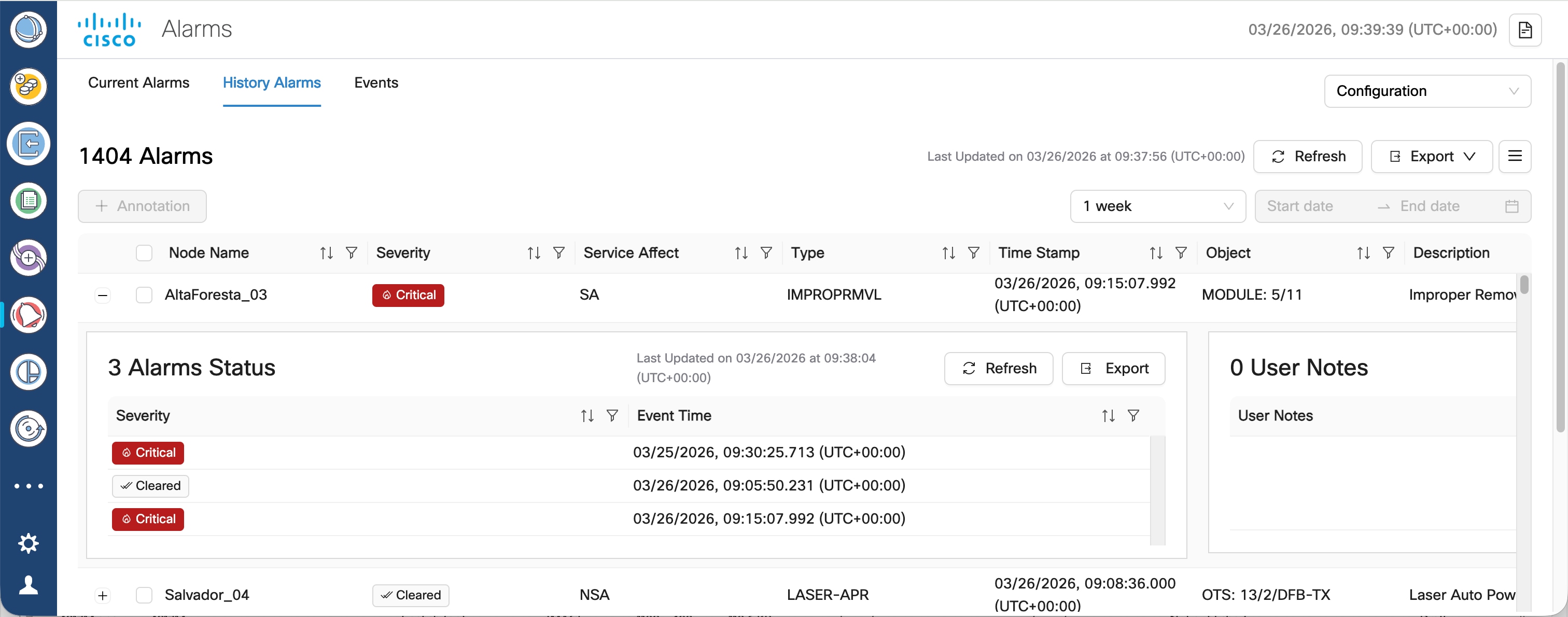
Click HistoryHistory Alarms to view the inactive or previous alarms. The details of each alarm based on each node and alarm type are displayed in the form of a cascading list and tables. Use the Custom Date Range Custom Date Range drop down option to view the history alarms based on different dates or time periods.
Figure 9. Alarm History Expanded View
Choose a time period for which you want to view the alarm history from the Select Time period drop down list, or choose a custom date range.
The history displays both cleared and active alarms for the selected circuit within the specified time range.
Note
You can select any 3-month range from the past 78 weeks to retrieve alarm history data.
Alarm history queries are rate limited. You can query up to 5 alarms history in a minute.
Click any cross-launch icon available under the Object column for any node to cross-launch to the corresponding Cisco Optical Site Manager panel.
Click Export to export the alarms details.
Note
You can export the table content to an excel file using the Table View option which has only the visible portion of the table appearing in the file or export the entire table content at once.
Click Refresh button to refresh the alarms status.
Note
If you apply a filter and click the Refresh button, the status is refreshed as per the filter you have applied.
Use the Filter option by clicking on the filter icon appearing in each column.
Note
The filter option allows you to search the alarm details based on the selected filter.
When you apply any filter in the Alarms screen, the Critical, Major, Minor and Warning counters they do not update their values as per the individual status of the alarms but only the count of each type of alarm.
The manage alarms task is complete.
Filter and review alarm details
Use this procedure to manage alarms in Cisco Optical Network Controller. Complete this task when you need to configure, verify, or manage the related network operation.
The Alarms screen displays all the alarm details for each node based on the severity level. You can view both the active alarms and the previously active alarms in this screen.
Figure 10. Alarms
For viewing the active alarms using AlarmsCurrent Alarms tab and the other for previous alarms using HistoryHistory Alarms tab.
Indicates whether the alarm is service affecting or non-service affecting.
NSA, SA
Location
The physical location of the affected equipment.
Direction
The direction of the alarm.
Receive,
User Tag
User-defined tags for categorizing and filtering alarms.
Note
User tags propagate from parent to child components of a chassis by default. A user tag on a child component overrides the inherited tag from its parent.
User Tag information comes from Cisco Optical Site Manager. See User Tags.
User tags are not supported on system-level and device alarms.
User tags can apply CLLI (Common Language Location Identifier), a standardized 11-character code that uniquely identifies geographic locations and equipment for network sites, network support sites, and customer locations.
Custom tags/labels
User Notes
User-added notes or comments related to the alarm.
Free-form text
Acknowledge
Indicates whether the alarm has been acknowledged.
Acknowledged, Unacknowledged
UUID
Unique Universal Identifier for the alarm.
UUID string
Correlation Type
The type of correlation applied to the alarm.
Network Level, Node Level
Note
You can filter the alarms table based on the fields. You can filter alarms to show only network-level or node-level correlated alarms.
Before you begin
Follow these steps to manage alarms:
Procedure
Use the Sort option by clicking on the sort icon appearing in each column.
Note
The sort option allows you to sort the alarm details based on the order you have selected.
Click on Critical, Major, Minor, Warning, and Cleared alarm types to filter and display the alarms belonging to each type.
Use the Acknowledge column in the table to view the acknowledged or unacknowledged alarms.
Note
To acknowledge or unacknowledge any particular alarm, select the node from the table and then click on Change Status. From the drop down, select Acknowledge or Unacknowledge option to acknowledge or unacknowledge the alarm of the selected node.
If an alarm is acknowledged, it appears with a green check mark in the table.
Acknowledged alarms also display the date and time-stamp details.
Up to 500 alarms can be acknowledged or unacknowledged at once.
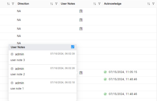
Use the User Notes column in the table to view the user notes added by any user.
Note
To add a user note, select the node and click on Annotation option. Enter the user note details and click on Add. The newly added user note appears in the User Notes column in the table.
Multiple user notes can be added to the same node or alarm.
If you click on the user notes icon in the User Notes column, it will display all the user notes added for the selected node or alarm.