Cisco Crosswork Network Controller 7.2 Administration Guide

PDF

Providers

Want to summarize with AI?

Log in

Use the topics in this section to create, edit, import, export, and delete providers and monitor their reachability.


Crosswork Network Controller components depend on external services, such as Cisco Crosswork Network Services Orchestrator (NSO) and Segment Routing Path Computation Element (SR-PCE), to perform operations like configuration modifications and segment routing path calculations. To manage access and facilitate information sharing among Crosswork Network Controller components, each external service must have a configured provider that belongs to a specific provider family (for example, NSO or SR-PCE).

A provider family is a service grouping that

  • specifies the type of external service offered to the Crosswork Network Controller, and

  • defines the parameters unique to the service type.

The system stores provider connectivity details and makes this information available to applications interacting with those external platforms.


Provider families

Crosswork Network Controller supports different types, or families, of providers. Each provider family supplies its own mix of special services, and each comes with unique requirements and options.

Table 1. Supported provider families

Provider family

Description

NSO

Instances of Cisco Network Services Orchestrator (Cisco NSO), used to configure network devices. See Add a Cisco NSO provider.

SR-PCE

Instances of Cisco Segment Routing Path Computation Elements (Cisco SR-PCE) containing the configuration information needed to allow Cisco Crosswork applications to communicate with and retrieve segment routing information for the network. See Add SR-PCE providers.

WAE

Instances of Cisco WAN Automation Engine (Cisco WAE) provide "what if" analysis used to evaluate network changes. See Add Cisco WAE providers .

Syslog Storage

Instances of storage servers (remote or on the Cisco Crosswork application VM itself) where you want to store syslogs and other data retrieved from devices by KPIs and playbooks. See Add syslog storage providers.

Alert

Instances of providers (such as Cisco Crosswork Situation Manager) to which alerts collected during KPI monitoring are to be forwarded. See Add an alert provider

Proxy

Instances of proxy providers. See Add proxy providers

Accedian (ACCEDIAN_PROXY)

Instances of Accedian Skylight providers. See Add Accedian Skylight as provider for more details.


Provider dependency

This section explains the provider configurations required for each system component.

Table 2. Provider dependency matrix

Cisco Crosswork Network Controller Component

Provider Type

NSO

SR-PCE

WAE

Syslog Storage

Alert

Proxy

Element Management Functions

Optional

Optional

Optional

Optional

Optional

Optional

Optimization Engine

Optional

Mandatory

Required protocol is HTTP.

Optional

Optional

Optional

Optional

Active Topology

Mandatory

Required protocols are HTTPS and SSH (for NSO backup)

Mandatory

Required protocol is HTTP.

Optional

Optional

Optional

Optional

Service Health

Mandatory

Required protocols are HTTPS and SSH (for NSO backup)

Mandatory

Required protocol is HTTP.

Optional

Optional

Optional

Optional

Change Automation

Mandatory

Required protocols are HTTPS and SSH (for NSO backup)

Optional

Optional

Optional

Optional

Optional

Health Insights

Mandatory

Required protocols are HTTPS and SSH (for NSO backup)

Optional

Optional

Optional

Optional

Optional

Note

Configuring a syslog storage provider with Change Automation and an alert provider with Health Insights is beneficial but not mandatory.


Manage Provider Access

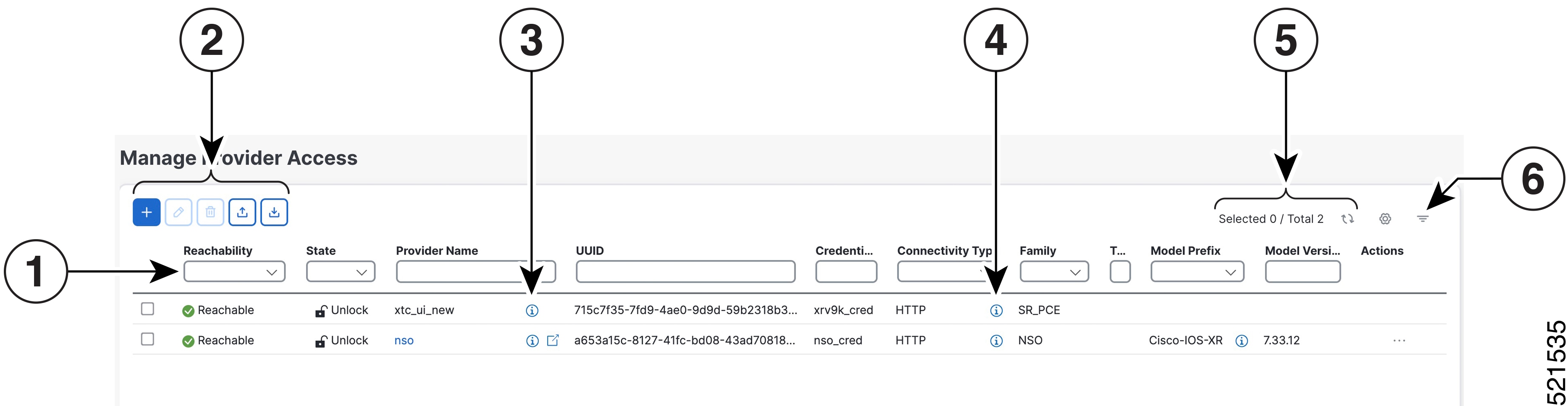
The Manage Provider Access page allows you to easily access tasks to create and manage providers. To navigate to this page, choose Administration > Manage Provider Access.

Figure 1. Manage provider access page
Manage provider access page
Table 3. Manage provider access page items
Item Description

1

The icon shown next to the provider in this column indicates the provider's Reachability.

2

Click Add icon to add a provider. See Add a provider.

Click Edit icon to edit the settings for the selected provider. See Edit provider settings.

Click Delete icon to delete the selected provider. See Delete providers.

Click Import icon to import new providers or update existing providers from a CSV file. You can also download a CSV file template by clicking this icon. The template includes sample data that you can use as a guide for building your own CSV file. See Import providers.

Click Export icon to export a provider to a CSV file. See Export providers.

3

Click Details icon next to the provider in the Provider Name column to open the Properties pop-up window, showing the details of any startup session key/value pairs for the provider.

4

Click Details icon next to the provider in the Connectivity Type column to open the Connectivity Details pop-up window, showing the protocol, IP, and other connection information for the provider.

5

Click Refresh icon to refresh the Providers window.

Click Settings icon to choose which columns are visible in the Providers window.

6

Click Set Filter icon to set filter criteria on one or more columns in the Providers window.

To clear a filter, click the corresponding [X] in the Filters menu.

Avoid topology sync issues during provider updates

Wait for the system to respond before making another provider update. For example, leave a pause between adding, deleting, or reading providers. If actions are performed too quickly, topology services may not reflect the changes. If you notice that topology is not synchronized, restart the topology service.


Add a provider

Before you begin

Review the configuration requirements for your provider family. For more information, see Provider families.

Use this procedure to add a new external provider. Once you add the provider, you can map it to the managed devices.

To add a provider, complete these steps:

Procedure

1.

Choose Administration > Manage Provider Access > Add icon.

2.

Enter required provider details. For specific field definitions, see Add provider window fields.

3.

Click Save to add the new provider.

4.

Repeat the steps to add more providers.


Add provider window fields

The table lists the Add Provider window fields and their descriptions.

Table 4. Fields in the Add Provider window (*=Required)
Field Description

* Provider Name

The name for the provider that will be used to refer to it in the Cisco Crosswork application. For example: Linux_Server.

The name can contain up to 128 alphanumeric characters, as well as dots (.), underscores ("_") or hyphens ("-"). No other special characters are allowed.

* Credential profile

Select the name of the credential profile that is used by the Cisco Crosswork application to connect to the provider.

* Family

Select the provider family.

Connection type(s)

* Protocol

Select the principal protocol to be used to connect to the provider. For information on provider configurations required for each system component, see Provider dependency matrix.

To add more connectivity protocols for this provider, click Add icon at the end of the first row.

To delete a protocol you have entered, click Delete iconshown next to that row.

You can enter multiple sets of connectivity details, including those for the same protocol.

* Server details

Select and provide one of these options:

  • IP Address (IPv4 or IPv6) and subnet mask of the provider's server.

  • FQDN (domain name and host name)

* Port

Enter the port number to use to connect to the provider's server. This is the port corresponding to the protocol being configured. For example, if the protocol used to communicate with the provider server is SSH, the port number is usually 22.

Timeout(sec)

Enter the amount of time (in seconds) to wait before the connection times out. The default is 30 seconds.

* Encoding type

Required if you are adding a Accedian_proxy provider. The available options are JSON, BYTES, PROTO, ASCII, and JSON IETF. Based on device capability, each device supports a single encoding format at a time.

Model prefix info

Note

The Model and Version fields do not apply to single VM deployments of Crosswork Network Controller.

* Model

Required if you are adding a Cisco NSO provider: Select the model prefix that matches the NED CLI used by Cisco NSO.

Valid values are:

  • Cisco-IOS-XR

  • Cisco-NX-OS

  • Cisco-IOS-XE

For telemetry, only Cisco-IOS-XR is supported.

To add more model prefix information for this Cisco NSO provider, click the Add icon at the end of any row in the Model Prefix Info section.

To delete a model prefix you have entered, click the Delete icon shown next to that row.

* Version

Required only if you are adding a Cisco NSO provider: Enter the Cisco NSO NED driver version used on the NSO server.

Provider properties

Property key

Enter the name of the key for the special provider property you want to configure.

Provider properties determine how the Cisco Crosswork Network Controller component interacts with each provider. The need for these properties and their types vary by provider family. Additional details are documented in topics dedicated to adding specific providers in this guide. The system does not validate provider properties. Ensure that you enter properties valid for the provider.

Note

In a two network interface configuration, the Cisco Crosswork applications default to communicating with providers using the Management Network Interface (eth0). You can change this behavior by adding Property key and Property value as outgoing-internal and eth1 respectively. This is most often necessary when creating the SR-PCE provider, as its management interface may reside on the data network instead of the management network.

Property value

Enter the value to assign to the property key.

To add more special properties for this provider, click Add icon at the end of any key/value pair in the Provider properties section.

To delete a key/value pair you have entered, click Delete icon shown next to that pair.


Import providers

Before you begin

Importing providers from a CSV file adds any providers not already in the database, and overwrites any existing providers with the same name. For this reason, export a backup of all your current providers before starting the import. For instructions, see Export providers.

Use this task to quickly onboard several providers at once. To create a CSV file that specifies providers and then import it into the Crosswork Network Controller, complete these steps:

Procedure

1.

Choose Administration > Manage Provider Access.

2.

Click Import icon to open the Import providers panel.

3.

If you have not already created a provider CSV file to import:

  1. Click the Download sample 'Provider template (*.csv)' file link and save the CSV file template to a local storage resource.

  2. Open the template using your preferred tool. Begin adding rows to the file, one row for each provider.

    Use a semicolon to separate multiple entries in the same field. Use two semicolons (;;) with no space between them to indicate that you are leaving the field blank. When you separate entries with semicolons, the order in which you enter values is important. For example, if you enter SSH;SNMP;NETCONF;TELNET in the connectivity_type field and you enter 22;161;830;23 in the connectivity_port field, the order of entry determines the mapping between the two fields:

    • SSH: port 22

    • SNMP: port 161

    • NETCONF: port 830

    • Telnet: port 23

    Delete any sample data rows before saving the file, or they will be imported along with the data you want. The column header row can stay, as it is ignored during import.

  3. Save the completed CSV file.

4.

Click Browse, select your completed CSV file and click Open.

5.

With the CSV file selected, click Import.

The provider information you imported should now be displayed in the Providers window.

6.

Review the import results. Resolve any errors reported during the import and verify provider details to confirm connection.


Cisco NSO providers

Network Services Orchestrator (NSO) acts as the configuration engine enabling service and transport provisioning, including VPN services and segment routing policies. Crosswork Network Controller integrates NSO providers to offer unified device lifecycle management, service orchestration, and visualization, providing a single pane of glass for network and service views. Cisco NSO providers in Crosswork Network Controller serve as a network management component that:

  • enables Crosswork Network Controller to configure devices based on their expected functions,

  • allows optional configuration of MDT sensor paths for data collection, and

  • delivers essential device management, configuration, and maintenance services.

NSO function packs

The Cisco NSO sample function packs offer a starting point for VPN service provisioning functionality in Crosswork Network Controller. While some samples can be used “as is” in limited network configurations, they are intended to demonstrate the extensible design of Crosswork Network Controller.

  • For answers to common questions, consult Cisco DevNet or Cisco Customer Experience representatives.

  • Support for further customization of samples for your specific use cases can be arranged through your Cisco account team.

  • Refer to View installed NSO function packs to monitor the state of the installed NSO function packs.

  • The NSO Function Pack deployment via Crosswork Network Controller UI is supported for NSO system installation and as a root user. For detailed deployment information, see the Cisco Crosswork Network Controller 7.2 Installation Guide.


Requirements for adding NSO providers

Required configurations for adding NSO providers

Ensure these configuration requirements are met prior to adding an SR-PCE provider.

Required information for adding NSO providers

You must have this information when adding a SR-PCE provider.

  • The name you want to assign to the Cisco NSO provider.

  • The Cisco NSO NED device models and driver versions used in your topology. You can find the Cisco NSO version using the version command.

  • The Cisco NSO server IP address or FQDN (Domain name and host name). When NSO is configured with HA, use the management VIP address as the IP address.

  • The NSO cross launch feature is not available for user roles with read-only permissions.


NSO layered service architecture (LSA) deployment

Crosswork Network Controller supports the deployment of Cisco NSO Layered Service Architecture (LSA). An NSO layered service architecture is a network management framework that

  • supports deployment of multiple device nodes for improved memory usage and provisioning throughput,

  • organizes NSO providers into customer-facing (CFS) and resource-facing (RFS) roles for service management, and

  • automates the identification and role assignment of each NSO provider to streamline operations and scalability.

In an LSA deployment, only one CFS provider is permitted. This provider encompasses all services, while RFS (resource-facing service) providers manage individual devices. On the Manager Provider Access page, the Type column identifies whether the NSO provider is CFS.

Key considerations for NSO LSA deployment

  • Enable LSA settings before adding an NSO LSA provider. For details, see Enable layered service architecture (LSA).

  • If LSA settings are not enabled or provider property values are misconfigured, perform the recommended recovery steps mentioned in the NSO LSA setup recovery section.

  • Ensure that RFS node IP addresses configured on the CFS match those shown in the user interface. A mismatch generates the error: "LSA cluster is missing RFS providers."

  • For a CFS node, only the forward property key is used.


Enable layered service architecture (LSA)

Use this procedure to configure LSA. This provides scalability by spreading network devices across multiple NSO instances, using your preferred distribution method.

To enable LSA, complete these steps.

Procedure

1.

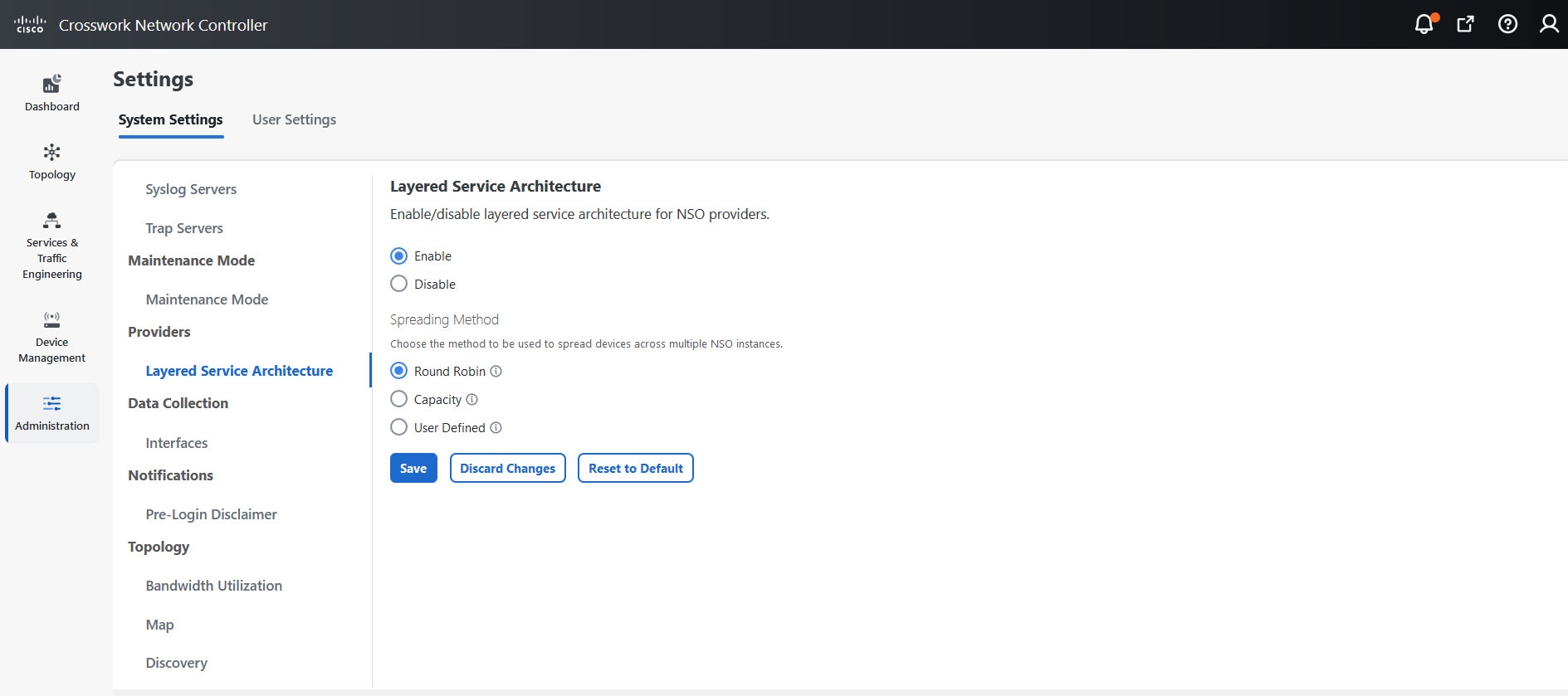
Choose Administration > Settings > System settings > Layered service architecture.

The Layered service architecture page appears.
Figure 2. Layered service architecture page
Layered service architecture page
2.

Select Enable.

3.

Select the method to distribute devices across multiple NSO instances:

  • Round Robin: Evenly distributes devices to RFS nodes in a cyclical manner (for example, Device 1 to RFS1, Device 2 to RFS2, and so on).

  • Capacity: Assigns devices to each RFS instance based on its available capacity.

  • User Defined: Assigns devices to specific NSO providers as specified in the device settings. For more details, see Add devices individually through the UI.

4.

Click Save.

Note
After saving, you cannot disable LSA without first removing all NSO providers.

NSO LSA setup recovery

Use this procedure to recover a misconfigured NSO LSA setup.

To recover the LSA setup, complete these steps.

Procedure

1.

Remove the NSO providers and associated devices in Device Management.

2.

Clean up the associated services in the Cisco NSO application.

3.

Enable LSA settings and add the the NSO LSA provider with correct property values.

4.

Add the NSO providers and devices again to Crosswork Network Controller, and map them to the Crosswork Data Gateway.

5.

Perform the sync operation on the NSO nodes (RFS and CFS) to sync the devices correctly.

The NSO LSA functionality is recovered as expected.

Embedded NSO for single VM deployment

Crosswork Network Controller deployed on a single VM with the Advantage package, uses an embedded NSO instead of an external NSO. The embedded NSO comes bundled as part of the Crosswork Network Controller Advantage package and is automatically installed when the package is deployed on a single VM.

When the embedded NSO is installed on the Crosswork Network Controller:

  • An NSO provider entry is automatically onboarded on the Providers page.

  • An SSO service provider entry supporting NSO cross-launch is automatically added on the SSO page.

  • The embedded NSO provider and the SSO service provider entries cannot be edited or deleted.


Add a Cisco NSO provider

Before you begin

Use this procedure to when you need to enable device onboarding and management between Cisco NSO and Crosswork Network Controller.

Crosswork Network Controller does not continuously scan NSO for device status changes. New device addition to NSO is discovered only when there is an explicit action in Crosswork Network Controller that interacts with NSO.

To onboard newly added devices from NSO to Crosswork Network Controller, perform an NSO action or update and save the NSO provider policy details.

  • Perform any NSO action for a device (from Device Management > Network Devices.

  • Edit and save the policy details of an existing NSO provider (select Actions > Edit policy details > set Onboard from to TRUE > Save) to trigger Crosswork Network Controller to rescan NSO.

To add a Cisco NSO provider, complete these steps:

Procedure

1.

Choose Administration > Manage Provider Access > Add icon.

2.

Enter these provider field values:

  1. Provider name: Enter a name for the provider.

  2. Credential profile: Select the previously created Cisco NSO credential profile.

  3. Family: Select NSO.

  4. Configure connection properties:

    • Protocol: Select HTTPS and/or SSH. For more information, see Provider dependency matrix.

      Note

      To use the Backup NSO option during backup, configure the SSH connectivity protocol in the NSO provider; otherwise, the backup will fail.

    • Server details: Provide the IP address (IPv4 or IPv6) or FQDN (domain or host name) of the server.

      If you update the IP address or FQDN of the NSO provider, detach and reattach devices from the associated virtual data gateway. If you fail to do this, the provider changes will not be reflected in MDT collection jobs.

    • Server details: Provide the IP address (IPv4 or IPv6) or FQDN (domain or host name) of the server.

    • Port: Enter the appropriate port number. For HTTPS, enter the port that corresponds with what is configured on the NSO VM in etc/ncs/ncs.conf to access NSO using HTTPS. NSO uses 8888 as default port.

    • Timeout (Optional): Enter the amount of time (in seconds) to wait before timing out the connection to the NSO server. The default is 30 seconds.

    Note

    If you set the Site location parameter in NSO, you can determine if geo-fencing is violated during testing when Crosswork Network Controller and the active NSO are not in the same site location. Crosswork Network Controller will also raise and clear alarms if a geo-fence violation is detected.

  5. Configure the model prefix information:

    • Model: Select Cisco-IOS-XR, Cisco-NX-OS, or Cisco-IOS-XE. Add a model for each type of device that will be used in the topology. If you have more than one, add another supported model.

    • Version: Enter the NED software version installed for the device model in NSO.

  6. For Provider properties, enter the key and value pairs as needed.

    Property key

    Value

    forward

    Set to true if you need to allow provisioning operations from the Crosswork Network Controller UI and enable the northbound interface to NSO through the Crosswork API gateway.

    Note

    The default value of forward is "false". If this is not changed, devices added to Crosswork Network Controller will not be added to NSO. This setting is used in conjuction with the Edit Policy option (see Edit the NSO provider policy).

    nso_crosslaunch_url

    Note

    For NSO standalone providers only.

    Enter the URL to enable cross-launching NSO application from the Crosswork Network Controller UI.

    Example format: https://<NSO IP address/FQDN>: port number

    Requires a valid protocol (HTTP or HTTPS), and the provider must be reachable.

    The cross launch icon (Close Panel icon) is displayed in the Provider Name column. Alternately, you can cross launch the NSO application using the launch icon located at the top right corner of the window.

    input_url_prefix
    Note

    For NSO LSA providers only.

    Enter the RFS ID.

    Example format: /rfc-x, where x refers to the number of the RFS node.

    For RFS node 1:

    input_url_prefix: /rfc-1
3.

Click Save.

What to do next

(Optional) Configure the NSO site name


Configure the NSO site name

You can configure the site name for NSO from the NCS backend. The site name appears as a read-only value on the NSO provider in the Crosswork Network Controller UI.

To configure the NSO site name, complete these steps.

Procedure

1.

Log in to ncs_cli in configuration mode.

2.

Set hcc dns member master ip-address nso1-mgmt-IP location site1-location

3.

Set hcc dns member standby ip-address nso2-mgmt-IP location site2-location

4.

Commit your changes.


View installed NSO function packs

Crosswork Network Controller allows you to monitor the operational status of installed NSO function packs.

To view installed NSO function packs, complete these steps.

Procedure

1.

Choose Administration > Crosswork Manager.

2.

On the Crosswork Manager window, select the NSO deployment manager tab.

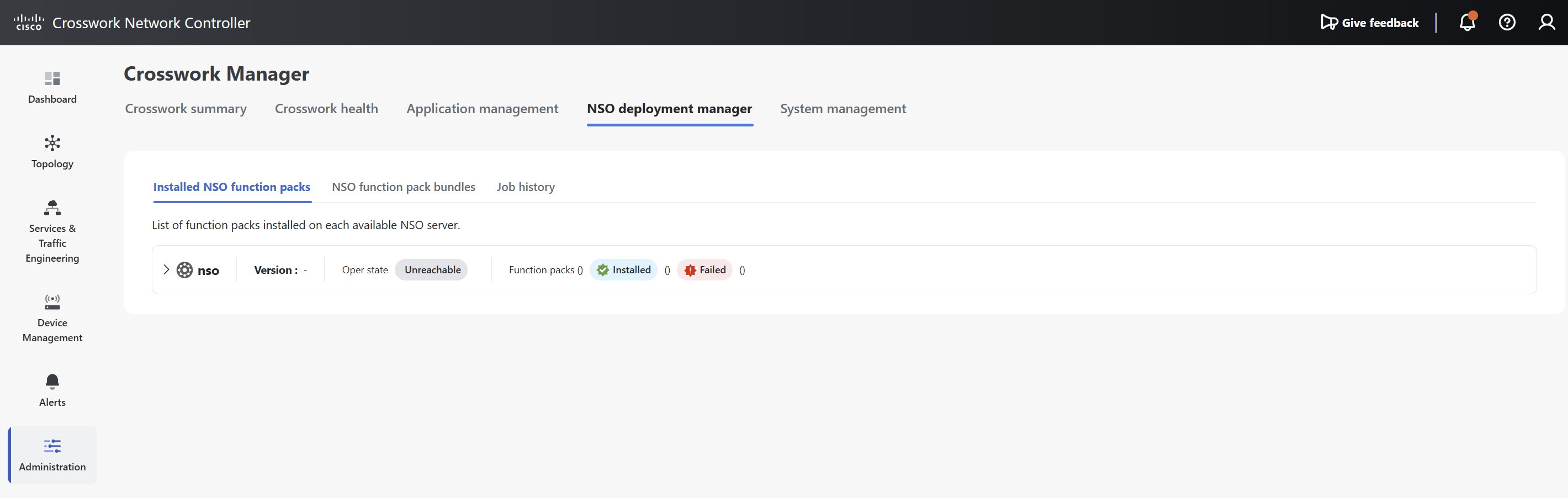
The Installed NSO function packs, NSO function pack bundles, and Job history tabs are displayed.

Note

You can also access this view from NSO provider entries in the Providers page by choosing Actions > View function packs.

The Installed NSO function packs tab lists all NSO function pack bundles deployed on the NSO server.

Figure 3. Installed NSO function packs
3.

Expand the bundles to view the number of function packs within each bundle, the function pack name, operational state (Up or Down), description, and version number.


Edit the NSO provider policy

Edit the NSO provider policy when you need to modify how devices are matched, onboarded, synchronized, or managed between Crosswork Network Controller and NSO.

To edit an NSO provider policy, complete these steps.

Procedure

1.

Choose Administration > Manage Provider Access.

2.

On a NSO provider, click Actions > Edit policy details.

The Edit policy details page for the selected NSO provider is displayed.

3.

Update the policy configuration fields to meet the specific requirements of your environment, ensuring the values align with your discovered devices. You can modify each criteria to define a targeted subset of devices and fine-tune the actions that DLM will perform.

For example, when a device's configuration is changed, DLM will attempt to sync with NSO and apply all relevant rules, such as MatchRule, OnboardToNSO, OnboardToRule.

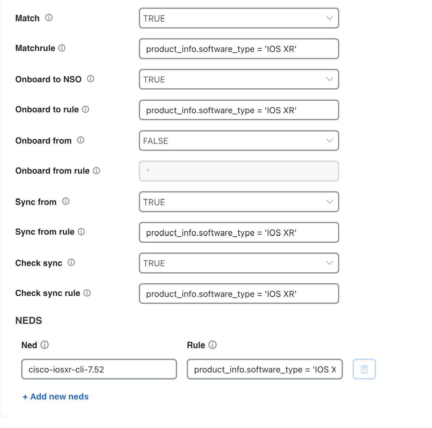
The different attributes you can edit within the NSO policy are:

Table 5. Editable policy attributes

Attribute

Description

Match

Set to True to match Crosswork Network Controller devices with those in NSO based on their IP address.

MatchRule

Enter an expression defining the subset of devices.

Onboard To NSO

Set to True to add missing devices to NSO.

Onboard To Rule

Enter an expression for onboarding a subset of devices.

Onboard From

Set to True to onboard devices from NSO to Crosswork network Controler if they are missing.

Onboard From Rule

Enter an expression for onboarding devices from NSO.

Sync From

Set to True to sync-from the NSO device after onboarding.

Sync From Rule

Enter an expression defining the subset of devices for sync-from.

Check Sync

Set to True to check sync status of NSO devices.

Check Sync Rule

Enter an expression for the subset of devices for check-sync.

NED

Specify the Network Element Driver (NED) to be used. By default, the latest CLI NED on NSO is used.

Rule

Enter an expression to define which devices should use a specific NED.

4.

Review your changes and click Save. The NSO policy rules are applied every time DLM synchronizes with NSO.

Specifying a NED for IOS-XR devices

The following image shows the policy attributes that set the cisco-iosxr-cli-7.52 NED for IOS-XR devices with a software version 6.23.

The entry for defining Rule is partially visible. Here is the complete text for your reference:

product_info.softwaretype='IOS XR' and product_info.softwareversion='6.23'

You can specify different criteria such as hostname, software type, and IP address and use operators like Eq (=), Neq (!=), GT (>), LT (<), GTEQ (>=), LTEQ (<=) and EqA (= =) to define the comparisons. Here are few more examples of expressions you can use to edit provider details:

  • Device information

    • host_name = 'host1'

    • product_info.manufacturer = 'Cisco Systems'

    • profile!='simulators'

  • Software and product details

    • product_info.software_type = 'IOS XR'

    • product_info.softwareversion = '6.23'

    • product_info.producttype = 'Cisco IOS XRv 9000 Router'

    • product_info.productfamily = 'Routers'

    • product_info.productseries = 'Cisco ASR 9000 Series Aggregation Services Routers'

  • Routing information

    • routing_info.router_loopback.inet_addr = '10.10.10.10'

    • routing_info.te_router_id = '10.8.8.52'

  • Combining criteria

    • Use the AND, OR commands to combine criteria. For example:

      product_info.software_type = 'IOS XR' OR product_info.software_type = 'IOS XE'

      product_info.software_type = 'IOS XR' AND product_info.software_version = '7.0.1'

  • Using wildcards

    Use the * symbol as a wildcard. For example, to match any IOS device, you can use IOS*. If no wildcard expression is used, the system performs an exact match of the string.

    • Exact match example

      If product_info.software_type = 'IOS XR' is specified, DLM matches only the devices where the software_type is exactly 'IOS XR'.

    • Wildcard example

      If product_info.software_type = 'IOS XR*' is specified, DLM matches all devices where the software_type starts with 'IOS XR'. This includes values such as 'IOS XR 1', 'IOS XRv'.

Note

For more information about editing NSO provider details and forming expressions using the attributes available in the Crosswork Inventory API, refer to the link DLM Inventory APIs.


Cisco SR-PCE providers

Cisco Segment Routing Path Computation Elements (Cisco SR-PCE) providers

  • supply device discovery, management, configuration maintenance, and route calculation services to Cisco Crosswork Network Controller components,

  • enable system access as part of SDN controllers in the management domain, and

  • support multi-AS topology and path calculations.

Requirements and additional information

Multi-AS topology and path calculations are supported if the complete topology is accessible to both the Crosswork Network Controller and each PCE. A single PCE cannot view a specific AS topology while another PCE views a different topology. Each PCE must have access to the entire topology view.

To learn and discover SR policies, Layer 3 links, and devices, at least one SR-PCE provider is required. Additionally, a second SR-PCE can be configured as a backup.


Requirements before adding SR-PCE providers

Required configurations for adding SR-PCE providers

Before adding an SR-PCE provider, ensure these configuration requirements are met to guarantee successful integration and operation.

  • Device and software requirements: Configure a device to act as the SR-PCE. Enable SR for IS-IS or OSPF protocols according to your device platform documentation, and configure an SR-PCE. For example, refer to the Segment Routing Configuration Guide for Cisco NCS 540 Series Routers.

    Note

    The Cisco IOS XRv 9000 is the recommended platform to function as the SR-PCE. For additional details, see Configure Segment Routing Path Computation Element. Beginning with Crosswork Network Controller version 7.1, the gRPC API instrumentation for PCE is mandatory. For supported IOS XR platforms, contact Cisco Support.

  • Credential profiles: Create a credential profile for the Cisco SR-PCE provider (see Create credential profiles) with these connection types:

    • gRPC: Required to discover topology, SR-MPLS, and SRv6 policies. See SR-PCE configuration examples for configuration examples.

    • Basic HTTP text-authentication: Required to process for RSVP, TreeSID and PCEP sessions. MD5 authentication is currently not supported.

      If the Cisco SR-PCE server you are adding does not require authentication, you must still provide a credential profile for the provider. Select a profile that does not use the HTTP protocol.

  • gRPC with TLS (Optional): If setting up gRPC with Transport Layer Security (TLS), a certificate must be generated and added with the Provider gRPC communication role. The certificate secures TLS communication between gRPC clients and the EMS server. The client should use ems.pem and ca.cert to initiate the TLS authentication. To update the certificate, copy the newly generated certificate to the required location and restart the server. For more details, refer to the Manage Certificates chapter in this guide..

  • High availability: For high availability, set up two separate Cisco SR-PCE providers with unique names and IP addresses, but with matching configurations.

Required information for adding SR-PCE providers

You must have this information when adding a SR-PCE provider:

  • The name you want to assign to the Cisco SR-PCE provider. This is usually the DNS hostname of the Cisco SR-PCE server.

  • The Cisco SR-PCE server IP address.

  • The interface you want to use to communicate between Cisco SR-PCE and the Crosswork Network Controller server.

  • SSH credentials for the PCE device to enable gRPC communication. PCE API credentials are used exclusively for HTTP-based communication.

  • Determine whether to auto-onboard devices that Cisco SR-PCE discovers and, if so, whether their management status should be set to off, managed or unmanaged when added.

Requirements for auto-onboarding managed devices

If you plan to auto-onboard devices that the Cisco SR-PCE provider discovers and set them to a managed state in the database:

  • Assign an existing credential profile for communication with the new managed devices.

  • Configure the credential profile with an SNMP protocol.


TLS configurations for SR-PCE

A TLS configuration is a network security feature that:

  • provides encrypted communication between SR-PCE and Crosswork applications

  • leverages existing gNMI certificates for simplified certificate management

  • supports server authentication (client authentication planned for future release), and

  • ensures compliance with network security requirements.

TLS is enabled by default in SR-PCE gRPC configurations. Upload valid certificates and configure the trust chain in Crosswork to ensure secure communication.

How TLS works with gRPC API

When TLS is enabled:

  1. SR-PCE presents its certificate to connecting clients

  2. Clients validate the certificate against the configured root CA

  3. An encrypted channel is established for all gRPC communications

  4. All API data transmission occurs over this secure channel


Configure TLS for gRPC API

Enable secure, encrypted communications for gRPC API in SR-PCE deployments using TLS, to protect data in transit and ensure compliance.

Configuring TLS for the SR-PCE gRPC API secures all API interactions using encryption. This process is essential in environments where data confidentiality and integrity are required, especially when using Crosswork Network Controller for device management.

Before you begin

Before configuring TLS for the SR-PCE gRPC API, make sure all prerequisites are met.

  • SR-PCE access and readiness

    • SR-PCE is installed and operational

    • Administrative access to the SR-PCE CLI and file system is available.

  • Certificates and keys

    • A Root CA certificate is available (used for gNMI collection).

    • Private key and certificate files are generated for SR-PCE.

Note

Crosswork Network Controller supports only server authentication and not mutual authentication (client certificate validation).

Use these steps to configure TLS on SR-PCE for gRPC API:

Procedure

1.

Verify TLS configuration on SR-PCE.

TLS is enabled by default when gRPC is configured. Check your current settings.

  1. Access the SR-PCE CLI.

  2. Check the gRPC configuration:

    show running-config grpc
  3. Ensure that the gRPC has these configurations:

    • no-tls is not configured under gRPC.

    • tls-mutual is not enabled under gRPC (it is disabled by default).

gRPC configuration shows TLS enabled without mutual authentication.
2.

Prepare the certificates.

Before uploading certificates to SR-PCE, ensure you have the private key, certificate, and root CA certificate.

The certificates must include the basicConstraints extension with CA:False, ensuring it cannot be used as a certificate authority or improperly delegated in a chain of trust.

3.

Upload certificates to SR-PCE.

  1. Transfer the private key and certificate to SR-PCE using SCP or SFTP.

  2. Copy files to the required locations:

    cp your-private-key.pem /misc/config/grpc/ems.key
    cp your-certificate.pem /misc/config/grpc/ems.pem
  3. Verify that the file has read permissions:

    ls -la /misc/config/grpc/
  4. Restart the emsd process to load the new certificates:

    process restart emsd
The process restarts successfully without errors.
4.

Configure the root CA certificate in Crosswork Network Controller UI.

If not already configured for gNMI collection:

  1. Log in to Crosswork Network Controller UI.

  2. Navigate to Administration > Certificate Management.

  3. Click the + icon to add a new certificate.

  4. Configure the certificate:

    • Device Certificate Name: Enter a name for the certificate.

    • Certificate Role: Select Provider gRPC Communication.

    • Secure gRPC CA certificate trustchain: Upload your root CA .pem file.

  5. Click Save.

    Note

    If a gNMI certificate already exists and multiple trust chains are needed, update the existing .pem file to include all required CA certificates.

After successful addition, the gNMI Certificate appears in the Certificates listed in Certificate Management > Certificates.
The gRPC configuration displays TLS enabled without mutual authentication.

What to do next

After configuration, verify that TLS is functioning correctly.
  1. Check the emsd process status:

    show process emsd
  2. Review gRPC service status:

    show grpc status
  3. Check logs for TLS-related errors:

    show logging | include TLS
    show logging | include grpc
  4. Test connectivity from a gRPC client using TLS.


Add SR-PCE providers

Before you begin

Ensure the configuration requirements defined in Requirements before adding SR-PCE providers are met prior to adding an SR-PCE provider.

To add one or more Cisco SR-PCE providers, complete these steps:

Procedure

1.

Choose Administration > Manage Provider Access > Add icon.

2.

Enter these SR-PCE provider field values:

  1. Provider: Enter a name for the SR-PCE provider.

  2. Credential profile: Select the credential profile you created for the SR-PCE provider.

  3. Family: Select SR_PCE.

  4. Configure connection properties.

    • Connection type(s) > Protocol:

      • Select HTTP and enter required fields. HTTP is required to process RSVP, TreeSID and PCEP sessions. The default port is 8080.

      • Select GRPC or GRPC_SECURE (gRPC with Transport Layer Security (TLS)) and enter required fields. These settings are required to process topology, SR-MPLS, and SRv6 policies. Only one of these options can be used. If GRPC_SECURE is selected, you must provide the trusted certificate in the Certificate profile field.

    • Server details: Enter the server IP address (IPv4 or IPv6) and subnet mask.

    • Port: Enter the port number.

    • Timeout (Optional): Enter the amount of time (in seconds) to wait before timing out the connection to the server. The default is 30 seconds.

  5. Provider properties: Enter property keys and values:

    Table 6. Property keys

    When the property key is..

    And the value is..

    Then..

    auto-onboard

    off

    when devices are discovered, the device data is recorded in the Cisco SR-PCE database, but is not registered in the Crosswork Network Controller Inventory Management database.

    Note

    Use this option if you plan to manually (via UI or CSV import) enter all of your network devices.

    unmanaged

    all devices that Crosswork Network Controller discovers will be registered in the Crosswork Network Controller Inventory Management database, with their configured state set to unmanaged. SNMP polling will be disabled for these devices, and no management IP information will be included. To get these devices into the managed state later, you will need to either edit them via the UI or export them to a CSV, make modifications and then import the updated CSV. You can also assign credential profiles by adding them to the device CSV file before import (the credential profiles must already exist).

    managed

    all devices that Cisco SR-PCE discovers will be registered in the Crosswork Network Controller Inventory Management database with their configured state set to managed.

    Typically suitable for an environment that has same device profiles, devices are managed by their TE router-ID, and all devices can be discovered by the Cisco SR-PCE.

    SNMP polling will be enabled for these devices, and Cisco SR-PCE will also report the management IP address (TE Router ID for IPv4, or IPv6 Router ID for IPv6 deployment). The devices will be added with the credential profile associated with the device-profile key in the SR-PCE provider configuration.

    Important considerations

    If you enable this option for IPv6 deployment, devices will still register as unmanaged in the inventory.

    When you delete an onboarded device that was added via SR-PCE discovery with auto-onboard set to managed, the topology service adds it again as unmanaged. This ensures that devices that have been removed are not automatically managed again unless they acquire a new TE-ID. To manage a rediscovered device, update its status manually.

    device-profile

    a credential profile name

    if the auto-onboard is set to managed and there is no valid device-profile set, the device will instead be onboarded as unmanaged.

    outgoing-interface

    eth1

    this enables Crosswork Network Controller access to SR-PCE via the data network interface when using a two NIC configuration.

    preferred-stack

    ipv4

    indicates a dual stack is present and IPv4 is preferred.

    ipv6

    indicates dual stack is present and IPv6 is preferred.

    NOT SET

    indicates no dual stack.

    pce

    off

    discovery of RSVP-TE tunnels and PCEP sessions (required for all LSP provisioning) is disabled.

    on

    discovery of RSVP-TE tunnels and PCEP sessions (required for all LSP provisioning) is enabled. This option is enabled by default.

    topology

    any value

    there is no impact.

    This property key is deprecated and should be manually removed if it still appears as an option. This property key is ignored, regardless if it is configured.

    Important considerations when using property keys:

    • Topology can be visualized even with auto-onboard as off and a device-profile is not specified.

    • If managed or unmanaged options are set and you want to delete a device later, you must either:

      • Reconfigure and remove the devices from the network before deleting the device from Crosswork Network Controller. This avoids Crosswork Network Controller from rediscovering and adding the device back.

      • Set auto-onboard to off, and then delete the device from Crosswork Network Controller. However, doing so will not allow Crosswork Network Controller to detect or auto-onboard any new devices in the network.

    • If you want to upgrade a device, change its state to unmanaged before starting the upgrade. After completing the upgrade, return the device to the UP state.

    • It is not recommended to modify auto-onboard options once set. If you need to modify them:

      1. Delete the provider and wait until deletion confirmation is displayed in the Events window.

      2. Add the provider again with the updated auto-onboard option.

      3. Confirm the provider has been added with the correct auto-onboard option in the Events window.

3.

Click Save to add the SR-PCE provider.

4.

Confirm that the SR-PCE provider shows a green Reachability status without any errors. You can also view the Events window to see if the provider has been configured correctly.

5.

Repeat this process for each SR-PCE provider.

What to do next

  • If auto-onboard is set to off, start onboarding devices.

  • If you opted to automatically onboard devices, choose Device Management > Network Devices to view the device list. To add more node information such as geographical location details, export the device list (.csv), update it, and import it back. If geographical location data is missing, you will only be able to see device topology using the logical map.


Cisco SR-PCE reachability issues

Use this procedure to resolve Cisco SR-PCE connectivity problems and restoring real-time topology status updates and notifications.

You can find SR-PCE reachability issues raised in the Events table and reachability status in the Providers page. Refer to Get provider details for details. If the SR-PCE goes down, the system displays all topology links in their last known state, and you stop receiving topology updates and notifications. When SR-PCE connectivity resumes, the Events table (Show Events icon) shows a reconnection message and the topology is updated accordingly.

You can troubleshoot reachability in these ways:

Procedure

1.

Check device credentials.

2.

Ping the provider host to verify network connectivity.

3.

Attempt a connection using the protocols specified in the provider's connectivity settings. For an SR-PCE provider, it is typically HTTP and port 8080.

4.

Check firewall rules and network configurations to ensure they are not blocking required ports or services.

5.

Check for Access Control List (ACL) settings on the Cisco SR-PCE host or any intervening devices that might restrict access.

6.

If the SR-PCE remains unreachable for a long period, or the system is not syncing or updating, delete the SR-PCE and add it again when connectivity returns.

  1. Execute the following command on the SR-PCE host to restart the process:

    # process restart pce_server
  2. Choose Administration > Manage Provider Access and delete the SR-PCE provider. On restoring connectivity, add the provider again.


Multiple Cisco SR-PCE HA pairs

Multiple Cisco SR-PCE HA pairs allow network operators to deploy up to eight redundant SR-PCE pairs for greater overall system resilience and scalability. Each HA pair of Cisco SR-PCE providers must have matching configurations and must support the same network topology. If one SR-PCE in a pair becomes unreachable, the system uses the secondary SR-PCE to discover the network topology. If both fail, the next HA pair takes over and so forth. The network topology will continue to be updated correctly and you can view SR-PCE connectivity events in the Events table (Show Events icon).

Multiple HA pair behavior

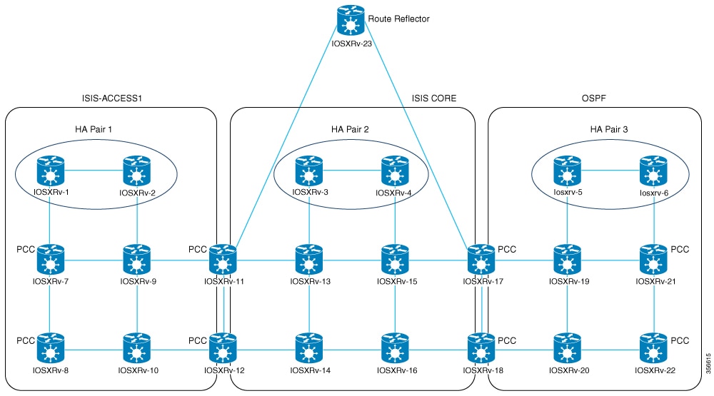
In the case of multiple SR-PCE HA pairs, each SR-PCE pair sees the same topology and manages only the tunnels created from its Path Computation Clients (PCCs). The figure shows a sample of a three SR-PCE HA pair topology.

  • HA Pair 1—PCE iosxrv-1 and iosxrv-2 only provision and discover tunnels whose headends are iosxrv-7 and iosxrv-8. Note that iosxrv-9 and iosxrv-10 are not PCC routers.

  • HA Pair 2—PCE iosxrv-3 and iosxrv-4 only provision and discover tunnels whose headends are iosxrv-11, iosxrv-12, iosxrv-17, and iosxrv-18. Note that iosxrv-13, iosxrv-14, iosxrv-15, and iosxrv-16 are not PCC routers.

  • HA Pair 3—PCE iosxrv-5 and iosxrv-6 only provision and discover tunnels whose headends are iosxrv-21 and iosxrv-22. Note that iosxrv-19 and iosxrv-20 are not PCC routers.

Figure 4. Sample 3 HA pair topology
Sample 3 HA pair topology
Note

When multiple SR-PCE HA pairs are configured, the SR-PCE used for topology discovery is selected randomly based on which SR-PCE responds first. All SR-PCEs across all HA pairs must maintain the same complete network topology to ensure consistent network operations.

Configure HA

The following configurations must be done to enable each pair of HA Cisco SR-PCE providers to be added in Crosswork Network Controller.

Note

There must be resilient IPv4 connectivity between both SR-PCEs to enable HA. The PCE IP address of the other SR-PCE should be reachable by the peer at all times.

Issue this commands on each Cisco SR-PCE device:

Enable the interface:
# interface <interface><slot>/<port>
ipv4 address <sync-link-interface-ip-address> <subnet-mask>
no shut

Enable HA:


# pce api sibling ipv4 <other-node-pce-address>
Establish a sync link between the two SR-PCEs:
# router static
address-family ipv4 unicast
<other-node-pce-ip-address>/<subnet-mask-length> <remote-sync-link-ip-address>

(Optional) # pce segment-routing traffic-eng peer ipv4 <other-node-pce-ip-address>

It should be entered for each PCC and not for other PCE nodes.

Enter this command on the PCC:

For SR Policies: # segment-routing traffic-eng pcc redundancy pcc-centric

For RSVP-TE Tunnels: # mpls traffic-eng pce stateful-client redundancy pcc-centric

Confirm sibling SR-PCE configuration

From the SR-PCE, enter the show tcp brief command to verify that synchronization between SR-PCEs in HA are intact:

#show tcp brief | include <remote-SR-PCE-router-id>

Confirm the information is correct:

Local address Foreign address

State

<local-SR-PCE-router-id>:8080

<remote-SR-PCE-router-id>:<any-port-id>

ESTAB

<local-SR-PCE-router-id>:<any-port-id>

<remote-SR-PCE-router-id>:8080

ESTAB

For example:

RP/0/0/CPU0:iosxrv-1#sh tcp brief | i 192.168.0.2:
Mon Jun 22 18:43:09.044 UTC
0x153af340 0x60000000 0 0 192.168.0.1:47230 192.168.0.2:8080 ESTAB
0x153aaa6c 0x60000000 0 0 192.168.0.1:8080 192.168.0.2:16765 ESTAB

In this example, 192.168.0.2 is the remote SR-PCE IP.

SR-PCE delegation

Depending on where an SR-TE policy is created, the following SR-PCE delegation occurs:

  • SR-PCE initiated—Policies configured on a PCE. SR-TE policies are delegated back to the source SR-PCE.

    Note
    • The policy can be PCE initiated even if it is created using the UI, but in that case it is not configured explicitly on SR-PCE.

    • RSVP-TE tunnels cannot be configured directly on a PCE.

  • PCC initiated—An SR-TE policy or RSVP-TE tunnel that is configured directly on a device. The SR-PCE configured with the lowest precedence is the delegated SR-PCE. If precedence is not set, then SR-PCE with the lowest PCE IP address is the delegated SR-PCE. The configuration example, shows that 10.0.0.1 is assigned a precedence value of 10 and will be the delegated SR-PCE.

    segment-routing
      traffic-eng
        pcc
          source-address ipv4 10.0.0.2
          pce address ipv4 10.0.0.1
            precedence 10
           !
          pce address ipv4 10.0.0.8
            precedence 20
           !
           report-all
           redundancy pcc-centric

    For RSVP-TE Tunnel:

    mpls traffic-eng
    interface GigabitEthernet0/0/0/0
    !
    interface GigabitEthernet0/0/0/1
    !
    interface GigabitEthernet0/0/0/2
    !
    pce
      peer source ipv4 192.168.0.02
      peer ipv4 192.168.0.9
        precedence 10
      !
      peer ipv4 192.168.0.10
        precedence 20
      !
      stateful-client
       instantiation
       report
       redundancy pcc-centric
       autoroute-announce
      !
    !
    auto-tunnel pcc
      tunnel-id min 1000 max 5000
  • Crosswork Network Controller SR-PCE initiated—An SR-TE policy that is configured using Crosswork Network Controller. SR-PCE delegation is random per policy.

    Note
    Only SR-TE policies or RSVP-TE tunnels created by Crosswork Network Controller can be modified or deleted by Crosswork Network Controller.

HA notes and limitations

  • It is assumed that all PCCs are PCEP connected to both SR-PCEs.

  • When an SR-PCE is disconnected only from Cisco Crosswork, the following occurs:

    • SR-PCE delegation assignments remain, but the SR-PCE that has been disconnected will not appear in Crosswork Network Controller.

    • You are not able to modify Cisco Crosswork SR-PCE initiated SR-TE policies if the disconnected SR-PCE is the delegated PCE.

  • In some cases, when an SR-TE policy that was created via the UI is automatically deleted (intentional and expected) from Crosswork Network Controller, a warning message does not appear. For example, if the source PCC is reloaded, the UI created SR policy disappears and the user is not informed.

  • In an extreme case where one SR-PCE fails on all links (to PCCs/topology devices) except the up-link to Crosswork Network Controller, topology information will not be accurate in Crosswork Network Controller. To resolve this, fix the connectivity issue or delete both SR-PCEs from the Provider page and re-add the reachable one.

  • PCE HA failover: After a PCE HA failover, when Crosswork Network Controller connects to the next available PCE, the Topology Service could take up to 2 hours to re-learn all L3 links and LSPs depending on the scale. During this time, newly created LSPs will remain in the queue and only appear in the UI after re-learning is complete.

  • When an SR-PCE goes down, Local Congestion Mitigation (LCM) enters a dormant stage. To exit this state, all SR-PCEs must be connected, and their associated topologies fully synchronized with the topology service. LCM will remain dormant until these conditions are met. It is important to note that LCM does not have visibility into the state of the SR-PCE redundancy set.


SR-PCE configuration examples

The following configurations are examples to guide you in a multiple SR-PCE setup for HA. Please modify accordingly.

ISIS single topology configuration for dual-stack networks

Cisco Crosswork Network Controller supports ISIS Single Topology in addition to Multi-Topology. To utilize this, your XTC devices must be configured for ISIS Single Topology. For Single Topology configurations, only global IPv6 addressing is supported; support for link-local IPv6 addressing is not included.

Device-side configuration example

RP/0/RP0/CPU0:iosxrv-2(config)#router isis [NAME]
RP/0/RP0/CPU0:iosxrv-2(config-isis)#address-family ipv6 unicast
RP/0/RP0/CPU0:iosxrv-2(config-isis-af)#single-topology

Configuration requirements for deploying and reporting SR MSL policies to PCE

Enable gRPC on devices and for SR-TE policies

RP/0/RP0/CPU0:L1-NCS5501#sh running-config grpc
grpc
 segment-routing
  traffic-eng
   policy-service
  !
 !
 port 57400
 no-tls

Advertise all SR policies to BGP-LS peers

This configuration enables your router to report all configured SR MSL policies—both active and inactive—into the link-state database. As a result, these policies can be advertised via BGP-LS to controllers or peers, providing full visibility and supporting network orchestration.

RP/0/RP0/CPU0:L1-NCS5501#sh running-config segment-routing traffic-eng distribute link-state 
segment-routing
 traffic-eng
  distribute link-state
   report-candidate-path-inactive
  !
 !
!

Prevent reporting MSL policies in PCEP

This configuration prevents SR MSL policies from being reported via PCEP. Since PCEP does not fully support MSL policies (it only advertises a single segment list, which can cause operational issues), it is recommended to remove the report-all command from the PCC configuration on the headend router.

RP/0/RP0/CPU0:L4-NCS560#sh running-config segment-routing traffic-eng pcc 
segment-routing
 traffic-eng
  pcc
   source-address ipv4 192.100.0.4
   pce address ipv4 100.100.0.1
    precedence 25
   !
   pce address ipv4 100.100.0.2
    precedence 50
   !
   !  Remove the following line to prevent reporting MSL policies to PCE
   !  report-all
   redundancy pcc-centric
   profile 1981
    autoroute
     include ipv4 all
     force-sr-include
    !
   !
  !
 !
!

Advertise SR MSL policies in link-state to PCE neighbor via BGP-LS

This configuration enables your router to advertise SR MSL policies in the link-state address family to a PCE neighbor over BGP. By establishing a BGP session with the PCE and including the address-family link-state link-state configuration, the router ensures that SR MSL policies are advertised and can be learned by the PCE.

Note

The link-state address family must be configured on both the headend and the PCE for successful exchange.

RP/0/RP0/CPU0:L1-NCS5501#sh running-config router bgp
router bgp 60
 neighbor <NEIGHBOR_IP>   ! PCE neighbor
  remote-as 60
  update-source Loopback0
  address-family ipv4 unicast
   next-hop-self
  !
  address-family ipv6 unicast
  !
  address-family link-state link-state. ! Enable BGP-LS for SR MSL policy advertisement
  !
 ! 

SRv6 data collection and traffic steering for DDM (Deterministic Demand Matrix) integration on Cisco IOS XR

Enable SRv6 locator accounting

This configuration enables the router to perform detailed accounting for IPv6 traffic specifically related to SRv6 locators. By tracking traffic on a per-prefix and per-nexthop basis, operators gain granular visibility into the usage and flow of SRv6-enabled services.

RP/0/RP0/CPU0:L1-NCS5501#sh running-config accounting 
accounting
 prefixes
  ipv6
   mode per-prefix per-nexthop srv6-locators
  !
 !
!

Enable SRv6 accounting data to telemetry

This configuration sets up model-driven telemetry on the router to stream SRv6 accounting data to external collectors. By defining specific sensor paths, the router can push operational data related to SRv6 locator accounting, enabling real-time monitoring, analysis, and orchestration of SRv6 network performance and traffic patterns.

RP/0/RP0/CPU0:L1-NCS5501#sh running-config telemetry model-driven
telemetry model-driven
 sensor-group cisco_models
  sensor-path Cisco-IOS-XR-infra-xtc-agent-oper:xtc/forwarding/policy-forwardings/policy-forwarding
  sensor-path Cisco-IOS-XR-fib-common-oper:cef-accounting/vrfs/vrf[vrf-name='default']/afis/afi[afi-type=ipv6]/pfx/srv6locs/srv6loc
 !
!

Enable customer/VRF traffic steering to SRv6 locators via BGP

This configuration enables an edge router to steer customer or VRF (Virtual Routing and Forwarding) IPv4 and IPv6 traffic into specific SRv6 locators using BGP.

RP/0/RP0/CPU0:L1-NCS5501#sh running-config router bgp 
router bgp 60
 bgp router-id <ROUTER_ID_IP>
 segment-routing srv6
  locator L1algo0
 !
 address-family ipv4 unicast
  network <ROUTER_ID_IP>/32
 !
 address-family vpnv4 unicast
  vrf all                ! If there are multiple VRF where traffic is ingressing, add srv6 locator in vrf all. 
   segment-routing srv6
    locator L1algo0
    alloc mode per-vrf
   !
  !
 !
 vrf ntt
  rd 200:200
  address-family ipv4 unicast
   segment-routing srv6   ! If there is only one VRF where traffic is ingressing, add srv6 locator in this vrf alone, if there is no VRF, then add the locator in neighbor address family 
    locator L1algo0
    alloc mode per-vrf
   !
   redistribute connected
  !
  neighbor <NEIGHBOR_IP>
   remote-as 61
   update-source GigabitEthernet0/0/0/0
   address-family ipv4 unicast
    route-policy PASS_ALL in
    route-policy PASS_ALL out
   !
  !
 !

Verify SRv6 traffic steering via CEF accounting

This command is used to verify that IPv6 traffic is being steered into SRv6 locators, rather than MPLS labels, by inspecting the CEF accounting statistics. It provides granular visibility, showing packet and byte counts for specific IPv6 prefixes that are associated with SRv6 locators.

sh cef ipv6 accounting
fccc:cc3e:3::/48
Accounting: 0/0 packets/bytes output (per-prefix-per-path mode)
 via fe80::2/128, Bundle-Ether1201
  path-idx 0
  next hop fe80::2/128
  Accounting: 200000/58400000 packets/bytes output  <<< Traffic packets for prefix fccc:cc3e:3::

Other sample SR-PCE configurations

Redundant SR-PCE configuration (on PCE with Cisco IOS-XR 7.x.x)


pce
 address ipv4 100.100.0.7
 state-sync ipv4 100.100.0.1
 api
  sibling ipv4 100.100.0.1

PCE configuration for enabling gRPC API on XR 25.2.1.x (IPv4 deployment)


conf t
  lslib-server
  !
  grpc
    port 57400
    no-tls
    address-family ipv4
    service-layer
    !
!
pce
  distribute link-state
  !
!
linux networking
  vrf default
    address-family ipv4
      default-route software-forwarding
    !
    address-family ipv6
      default-route software-forwarding
    !
  !
!
commit
Note

For secure gRPC deployment, remove no-tls.

Configure distribute link-state on all PCEs to inject SR policies into BGP-LS.

Enable gRPC API on XR 25.2.1.x (IPv6 deployment)


conf t
  lslib-server
  !
  grpc
    port 57400
    no-tls
    address-family ipv6
    service-layer
    !
!
pce
  distribute link-state
  !
!
linux networking
  vrf default
    address-family ipv4
      default-route software-forwarding
    !
    address-family ipv6
      default-route software-forwarding
    !
  !
!
commit
Note

For secure gRPC deployment, remove no-tls.

Configure distribute link-state on all PCEs to inject SR policies into BGP-LS.

Verify whether the topology is published in gRPC

sh lslib server topology-db

Verify the SR-MPLS LSP published in gRPC

show lslib server topology-db detail protocol sr

Redundant SR-PCE configuration (PCC)

segment-routing
 traffic-eng
  pcc
   source-address ipv4 100.0.0.1
   pce address ipv4 100.0.0.2
    precedence 200
   !
   pce address ipv4 100.0.0.3
    precedence 100
   !
   report-all
   redundancy pcc-centric

Redundant SR-PCE configuration (on PCC) for RSVP-TE

Note

Loopback0 represents the TE router ID.


ipv4 unnumbered mpls traffic-eng Loopback0
!
mpls traffic-eng
 pce
  peer source ipv4 200.100.200.1
  peer ipv4 209.165.0.6
   precedence 200
  !
  peer ipv4 100.100.0.0
   precedence 100
  !
  stateful-client
   instantiation
   report
   redundancy pcc-centric
   autoroute-announce
  !
 !
 auto-tunnel pcc
  tunnel-id min 1000 max 1999
 !
!

Sample Telemetry configuations

SR-TM configuation

telemetry model-driven
 destination-group crosswork
  address-family ipv4 5.5.5.5 port 9000
   encoding self-describing-gpb
   protocol tcp
  !
 !
 sensor-group SRTM
  sensor-path Cisco-IOS-XR-infra-tc-oper:traffic-collector/afs/af/counters/tunnels
  sensor-path Cisco-IOS-XR-infra-tc-oper:traffic-collector/vrf-table/default-vrf/afs/af/counters/prefixes
 !
 subscription OE
  sensor-group-id SRTM sample-interval 60000
  destination-id crosswork
  source-interface Loopback0
!
traffic-collector
 interface GigabitEthernet0/0/0/3
 !
 statistics
  history-size 10
Note

The destination address uses the southbound data interface (eth1) address of the Crosswork Data Gateway VM.

It is required to push sensor path on telemetry configuration via NSO to get prefix and tunnel counters. It is assumed that the Traffic Collector has been configured with all the traffic ingress interface. This configuration is needed for demands in the Bandwidth on Demand feature pack to work.

Telemetry sensor path

sensor-path Cisco-IOS-XR-infra-tc-oper:traffic-collector/afs/af/counters/tunnels/tunnel
sensor-path Cisco-IOS-XR-infra-tc-oper:traffic-collector/vrf-table/default-vrf/afs/af/counters/prefixes/prefix
 

Telemetry configuration pushed by Crosswork Network Controller to all the headend routers via NSO

telemetry model-driven
  destination-group CW_43dc8a5ea99529715899b4f5218408a785e40fce
    vrf default
    address-family ipv4 5.5.5.5 port 30500
      encoding self-describing-gpb
      protocol top
    !
  !
destination-group CW_4b3c69a200668b0a8dc155caff295645c684a8f8
  vrf default
  address-family ipv4 5.5.5.5 port 30500
    encoding self-describing-gpb
    protocol top
  !
!
sensor-group CW_43dc8a5ea99529715899b4f5218408a785e40fce
  sensor-path Cisco-IOS-XR-infra-tc-oper:traffic-collector/afs/af/counters/tunnels/tunnel
!
sensor-group CW_4b3c69a200668b0a8dc155caff295645c684a8f8
  sensor-path Cisco-IOS-XR-infra-tc-oper:traffic-collector/vrf-table/default-vrf/afs/af/counters/prefixes/prefix
!
subscription CW_43dc8a5ea99529715899b4f5218408a785e40fce
  sensor-group-id CW_43dc8a5ea99529715899b4f5218408a785e40fce sample-interval 300000
  destination-id CW_43dc8a5ea99529715899b4f5218408a785e40fce
!
subscription CW_4b3c69a200668b0a8dc155caff295645c684a8f8
  sensor-group-id CW_4b3c69a200668b%a8dc155caff295645c684a8f8 sample-interval 300000
  destination-id CW_463c69a200668b0a8dc155caff295645c684a8f8
  !
!

Traffic Collector configurations

Traffic Collector configurations (all Ingress traffic interface to be added below in the Traffic Collector)

RP/0/RSP0/CPU0:PE1-ASR9k#sh running-config traffic-collector
Fri May 22 01:14:35.845 PDT
traffic-collector
  interface GigabitEthernet0/0/0/0
  !
  statistics
    history-size 1
    collection-interval 1
    history-timeout 1
    history-minute-timeout
  !  
!
Add BGP neighbor next-hop-self for all the prefix (to show TM rate counters)
bgp router-id 5.5.5.5
address-family ipv4 unicast
  network 5.5.5.5/32
  redistribute static
!
address-family link-state link-state
!
neighbor 1.1.1.1
  remote-as 65000
  update-source Loopback0
  address-family ipv4 unicast
   next-hop-self
  !
!

Traffic collector tunnel and prefix counters

RP/0/RSP0/CPU0:PE1-ASR9k#show traffic-collector ipv4 counters prefix
Fri May 22 01:13:51.458 PDT
Prefix              Label         Base rate         TM rate        State
                                  (Bytes/sec)       (Bytes/sec)
-----------------  -------------  ---------------  --------------  -----------------
1.1.1.1/32          650001         3                0              Active
2.2.2.2/32          650002         3                0              Active
3.3.3.3/32          650003         6                0              Active
4.4.4.4/32          650004         1                0              Active
6.6.6.6/32          650200         6326338          6326234        Active
7.7.7.7/32          650007         62763285         62764006       Active
8.8.8.8/32          650008         31129168         31130488       Active
9.9.9.9/32          650009         1                0              Active
10.10.10.10/32      650010         1                0              Active
RP/0/RSP0/CPU0:PE1-ASR9k#stt
RP/0/RSP0/CPU0:PE1-ASR9k#show traffic-collector ipv4 counters tunnel
Fri May 22 01:13:52.169 PDT
RP/0/RSP0/CPU0:PE1-ASR9k#]
Path computation client (PCC) support

A path computation client (PCC) is a network device that

  • initiates path computation requests to an external path computation element (PCE),

  • reports the status and attributes of label-switched paths (LSPs) such as RSVP-TE tunnels or SR policies, and

  • establishes and manages Path Computation Element Protocol (PCEP) sessions with one or more PCEs for dynamic tunnel delegation and control.

Path computation clients (PCCs) can support delegation and reporting of multiple tunnel types, such as RSVP-TE tunnels and SR policies. For both functionalities to be supported on the same PCC, it is necessary to establish two separate PCEP connections with the PCEs. Each of these PCEP connections must use a unique source IP address, typically assigned to a loopback interface on the PCC.

Configuration example to set up PCEP connections for RSVP-TE tunnels on a Cisco IOS-XR

  • The IP address 192.168.0.2 is the source IP for the PCEP session. This IP is assigned to a loopback interface on the router, ensuring stability and uniqueness.

  • Two SR-PCEs are configured as peers for PCEP sessions. Each has a precedence value, with the lower precedence (10) indicating the preferred PCE for delegating RSVP-TE tunnels.

  • An auto-tunnel PCC feature is configured with a range of tunnel IDs (from 10 to 1000). These IDs are assigned to RSVP-TE tunnels initiated by the PCE, such as those created by Cisco Crosswork Optimization Engine.

mpls traffic-eng
interface GigabitEthernet0/0/0/2
admin-weight 1
!
interface GigabitEthernet0/0/0/3
admin-weight 1
  pce
    peer source ipv4 192.168.0.2
    peer ipv4 192.168.0.1
      precedence 10
     !    
    peer ipv4 192.168.0.8
      precedence 11
     !
    stateful-client
      instantiation
      report
     ! 
   !
   auto-tunnel pcc
    tunnel-id min 10 max 1000
   !
!
ipv4 unnumbered mpls traffic-eng Loopback0

rsvp
interface GigabitEthernet0/0/0/2
bandwidth 1000000
!
interface GigabitEthernet0/0/0/3
bandwidth 1000000
!
!

Add Cisco WAE providers

Before you begin

  • Create a credential profile for the Cisco WAE provider. For instructions, see Create credential profiles. This should be a basic HTTP/HTTPS text-authentication credential. MD5 authentication is not supported. If the Cisco WAE server you are adding does not require authentication, you must still supply a credential profile, but it can be any profile that does not use the HTTP/HTTPS protocol.

  • Know the name you want to assign to the provider. This is usually the DNS hostname of the Cisco WAE server.

  • Know the Cisco WAE server IP address and port. The connection protocol will be HTTP or HTTPS.

Cisco WAN Automation Engine (Cisco WAE) providers supply traffic and topology analysis to the Crosswork Network Controller components. The foundation software is Cisco WAE Planning, which provides a cross-sectional view of traffic, topology, and equipment state. It takes advantage of a predictive model that performs "what if" analysis of failure impacts.

To add one or more Cisco WAE providers using the Crosswork Network Controller UI, complete these steps. To add providers by importing CSV files, refer to the instructions in Import providers.

Procedure

1.

Choose Administration > Manage Provider Access > Add icon.

2.

Enter these provider field values:

  1. Provider name: Enter a name for the Cisco WAE provider.

  2. Credential profile: Select the credential profile you created.

  3. Family: Select WAE.

  4. Configure connection type properties:

    • Protocol: Select HTTP or HTTPS as per the credential profile you are using.

    • Server details: Enter the server IP address (IPv4 or IPv6) and subnet mask.

    • Port: Enter the appropriate port number (usually 8080 for HTTP, and 8843 for HTTPS).

    • Timeout (Optional): Enter the amount of time (in seconds) to wait before timing out the connection to the server. The default is 30 seconds.

3.

Click Save to add the provider.


Add syslog storage providers

Before you begin

  • Create a credential profile for the storage provider. For instructions, see Create credential profiles. This should be an SSH credential.

  • Know the name you want to assign to the storage provider. This is usually the DNS hostname of the server.

  • Know the storage provider's server IPv4 address and port. The connection protocol will be SSH.

  • Know the destination directory on the storage provider's server. You will need to specify this using the Provider properties fields.

To add one or more storage providers using the Crosswork Network Controller UI, complete these steps. To add providers by importing CSV files, refer to the instructions in Import providers.

Procedure

1.

Choose Administration > Manage Provider Access > Add icon.

2.

Enter these provider field values:

  1. Provider name: Enter a name for the storage provider.

  2. Credential profile: Select the credential profile you created.

  3. Family: Select SYSLOG_STORAGE.

  4. Configure connection type properties:

    • Protocol: Select SSH as the protocol to connect the provider.

    • Server details: Enter the server IP address (IPv4 or IPv6) and subnet mask.

    • Port: Enter the appropriate port number (usually 22 for SSH).

    • Timeout (Optional): Enter the amount of time (in seconds) to wait before timing out the connection to the server. The default is 30 seconds.

  5. To configure provider properties, enter this key/value pair:

    Property key: DestinationDirectory

    Property value: The absolute path where the collected data will be stored on the server. For example: /root/cw-syslogs

3.

Click Save to add the provider.


Add an alert provider

Before you begin

  • Create a credential profile for the alert provider. For instructions, see Create credential profiles. This should be a basic HTTP text-authentication credential. MD5 authentication is not supported. If the provider does not require authentication, you must still supply a credential profile. It can be any profile that does not use the HTTP protocol.

  • Know the name you want to assign to the alert provider. This is usually the DNS hostname of the server.

  • Know the alert provider's server IPv4 address and port. The connection protocol will be HTTP.

  • Know the URL of the alert server endpoint. You will need to specify this using the Provider properties fields.

An Alert provider is a destination to which you want to forward alerts collected during KPI monitoring (such as Cisco Crosswork Situation Manager). An alert provider must be capable of receiving and processing incoming alert packages. Currently, only one alert provider is supported.

To add an alert provider using the Crosswork Network Controller UI, complete these steps. To add an alert provider by importing CSV files, refer to the instructions in Import providers.

Procedure

1.

Choose Administration > Manage Provider Access > Add icon.

2.

Enter these provider field values:

  1. Provider name: Enter a name for the alert provider.

  2. Credential profile: Select the credential profile you created.

  3. Family: Select ALERT.

  4. Configure connection type properties:

    • Protocol: HTTP is pre-selected as the protocol to connect the provider.

    • Server details: Enter the server IP address (IPv4 or IPv6) and subnet mask.

    • Port: Enter the port number (usually 80 for HTTP).

    • Timeout (Optional): Enter the amount of time (in seconds) to wait before timing out the connection to the server. The default is 30 seconds.

  5. For provider properties, the alertEndpointUrl Property key is pre-entered. In the Property value field, enter the alert server endpoint only. For example, if the complete path to the endpoint is http://aws.amazon.com:80/myendpoint/bar1/, you would enter /myendpoint/bar1/ only.

3.

Click Save to add the provider.


Add proxy providers

Before you begin

  • Create a credential profile for each proxy provider. For instructions, see Create credential profiles. This should be a basic HTTP or HTTPS text-authentication credential.

  • Know the Resource Facing Service (RFS) node name added to the Customer Facing Service (CFS) node in your LSA cluster.

  • Know the name you want to assign to the provider. This is usually the DNS hostname of the proxy server.

  • Know the proxy server IP address and port. The connection protocol will be HTTP or HTTPS.

  • Ensure the Cisco NSO providers have been added. For more information, see Add a Cisco NSO provider.

  • For NSO proxy provider, create a credential profile with HTTP/HTTPS with Basic Authentication.

  • For ONC 1.0 proxy provider, create a credential profile with HTTPS with Basic Authentication.

You add a proxy providers to enable service provisioning through the Crosswork Network Controller interface. Crosswork Network Controller supports adding Cisco NSO and Cisco Optical Network Controller (ONC) v1.0 proxy providers.

  • NSO APIs are directly accessible if NSO is configured with an external IP address.

  • If NSO is deployed within a private network, then it will be reachable only through the Crosswork Network Controller interface. Proxy providers enables you to use Crosswork interface to perform service provisioning with NSO.

To add proxy providers, complete these steps:

Procedure

1.

Choose Administration > Manage Provider Access > Add icon.

2.

Enter these provider field values:

  1. Provider name: Enter a name for the proxy provider.

  2. Credential profile: Select the credential profile you created.

    Note

    For ONC provider, select the profile configured with ONC TAPI APIs, not the ONC UI credentials.

  3. Family: Select PROXY.

  4. Configure connection type properties:

    • Protocol: Select HTTP or HTTPS.

    • Server details: Enter the IP address (IPv4 or IPv6) and subnet mask of the NSO cluster or the ONC 1.0 cluster VIP.

    • Port: Enter the appropriate port number (usually 30603 for HTTPS).

    • Timeout (Optional): Enter the amount of time (in seconds) to wait before timing out the connection to the server. The default is 30 seconds.

  5. Configure Provider properties with these key and value pairs:

    Table 7. For NSO proxy provider

    Property key

    Property value

    forward true
    input_url_prefix
    Note

    Required only in case of RFS nodes.

    /<rfs-node-name>

    <rfs-node-name> refers to the name of the RFS node added to the CFS node in the LSA cluster.

    Table 8. For ONC 1.0 proxy provider

    Property key

    Property value

    forward true
    input_url_prefix /onc-tapi
    output_url_prefix /crosswork/onc-tapi
3.

Click Save to add the provider.


Get provider details

You can view details for each configured provider and check provider reachability in your Cisco Crosswork application. Use the Providers page to access information about each provider, including name, universally unique identifier (UUID), credential profile, and connectivity status. You can also view reachability status via different protocols.

Procedure

1.

Choose Administration > Manage Provider Access.

The Providers page displays all configured providers with details such as name, UUID, credential profile, and more.
Figure 5. Manage providers access
Manage providers access
2.

The icons in the Reachability column indicate whether a provider is reachable via the listed connectivity protocols.

Provider reachability is checked automatically after you add or modify a provider. For Change Automation and Health Insights, ongoing checks occur approximately every 5 minutes. For SR-PCE via the Optimization Engine, checks occur every 10 seconds.

Note

Change Automation events and Health Insights events apply only to cluster deployments of the Crosswork Network Controller. Optimization Engine events applies in all cases except single VM deployments of the Crosswork Network Controller Essentials tier.

3.

To view additional details for a provider:

  1. In the Provider Name column, click Details icon to view provider-specific key/value properties.

  2. In the Connectivity Type column, click Details icon to view detailed connectivity information for the provider. This information includes protocol, IP format, IP address, port, and timeout values.

  3. In the Model Prefix column, click Details icon to view the supported NED version(s) for a Cisco NSO provider's configured NED model prefix(es).

  4. Click Close icon to exit the details window.

If you encounter SR-PCE reachability problems, ensure HTTP and port 8080 are set, and see Cisco SR-PCE reachability issues.

For general provider reachability issues:

  1. Ping the provider host.

  2. Attempt a connection using the protocols specified in the provider’s connectivity settings.

    Use this CLI command to perform this check:

    curl -v -H "X-Subscribe: stream" "http://<ip-address>:8080/
    bwod/subscribe/json?keepalive-30&priority=5"
  3. Check your firewall setting and network configuration.

  4. Review Access Control List (ACL) settings on the provider host or intermediate devices that could restrict connectivity.


Edit provider settings

Before you begin

Export a CSV backup of the providers you want to change.

Use this procedure to update the settings for an existing provider. Provider changes can affect many devices in your network, potentially thousands in large environments.

Note
  • Before editing any provider settings, make sure you understand the impact of your changes. If you are unsure about the potential risk of making a change, contact Cisco services for guidance.

  • If modifying an SR-PCE provider, see related guidance in Add SR-PCE providers section; additional steps may be necessary.

To update an existing provider, complete these steps:

Procedure

1.

Choose Administration > Manage Provider Access.

2.

In the Providers window, select the provider to update and click Edit icon.

3.

Make necessary changes and click Save.

4.

Resolve errors and confirm provider reachability.

The provider settings are updated and propagated to mapped devices.

Delete providers

Use this procedure to remove providers that are no longer needed. Delete providers only when they are not actively associated with devices or credential profiles. The system alerts you if associations exist.

To delete providers, complete these steps:

Procedure

1.

Export a backup CSV file containing the provider you plan to delete. For instructions, see Export providers.

2.

(Optional) Check whether any devices are mapped to the provider and change the provider before deletion.

  1. Choose Device Management > Network Devices. The Network Devices tab is displayed by default.

  2. In the Network Devices window, enter the obsolete provider name in the Search field.

  3. Select the device that is mapped to the obsolete provider, and click Edit icon.

  4. Choose a different provider from the Provider drop-down list.

  5. Click Save.

3.

Choose Administration > Manage Provider Access.

4.

In the Providers window, select the provider(s) to delete.

5.

Click Delete icon and confirm when prompted.

The selected providers are deleted if they are not associated with any devices or credential profiles.


Export providers

You can export provider data to a CSV file. This is a handy way to keep backup copies of your provider information.

Note

You cannot edit a CSV file and then re-import it to update existing providers.

Procedure

1.

Choose Administration > Manage Provider Access.

2.

(Optional) In the Manage Provider Access page, filter the provider list as needed.

3.

Select the check boxes for the providers you want to export. To select all the providers for export, use the check box at the top of the column.

4.

Click Export icon. Depending on your browser, you will be prompted to select a path and file name for saving the CSV file, or to open the file immediately.

The selected providers are exported to a CSV file.