- Preface
- Basic Functionality
- Basic Configurations
- Configuring System
- Configuring Green Ethernet
- Configuring Thermal Protection
- Configuring Ports
- Configuring Security
- Configuring Aggregation
- Configuring Link OAM
- Configuring Loop Protection
- Configuring Spanning Tree
- Configuring MVR
- Configuring LLDP
- Configuring SyncE
- Configuring EPS
- Configuring MEP
- Configuring ERPS
- Configuring MAC Table
- Configuring VLANs
- Configuring VLAN Translation
- Configuring Ethernet Services
- Configuring Performance Monitor
- Configuring QoS
- Configuring HQoS
- Configuring Mirroring
- Configuring PTP
- Configuring sFlow
- Configuring Traffic Test
- Configuring Traffic Test Loops
- Configuring DDMI
- Configuring UDLD
- Configuring Flex Links
- Monitoring System
- Monitoring Green Ethernet
- Monitoring Thermal Protection
- Monitoring Ports
- Monitoring Link OAM
- Monitoring Security
- Monitoring Aggregation
- Monitoring Loop Protection
- Monitoring Spanning Tree
- Monitoring MVR
- Monitoring LLDP
- Monitoring Ethernet Services
- Monitoring Performance Monitor
- Monitoring PTP
- Monitoring MAC Table
- Monitoring VLANs
- Monitoring sFlow
- Monitoring DDMI
- Monitoring UDLD
- Monitoring Flex Links
- Diagnostics
- Maintenance
- Use Cases
Configuring
PTP
PTP Clock Configuration
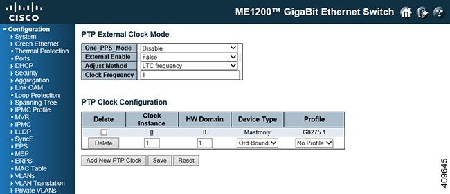
This feature allows you to configure and inspect the current PTP clock settings.
-
One_PPS_Mode: This drop-down list allows you to select the One_pps_mode configuration. The following values are possible: -
External Enable: This drop-down list allows you to configure the external cock output. The following values are possible: -
Adjust Method: This drop-down list allows you to configure the frequency adjustment configuration. -
LTC frequency: Selects Local Time Counter (LTC) frequency control.
-
SyncE-DPLL: Selects SyncE DPLL frequency control, if allowed by SyncE.
-
Oscillator: Selects an oscillator independent of SyncE for frequency control, if supported by the hardware.
-
LTC phase: Selects Local Time Counter (LTC) phase control (assumes that the frequency is locked by means of SyncE).
-
-
Clock Frequency: This will allow to set the Clock Frequency.The possible range of values are 1 - 25000000 (1 - 25MHz).
-
Delete: Check the corresponding check box and click Save to delete a clock instance.
-
Clock Instance: Indicates the Instance of a particular Clock Instance [0..3]. Click on the Clock Instance number to edit the Clock details.
-
HW Domain: Indicates the HW clock domain used by the clock.
-
Device Type: Indicates the Type of the Clock Instance. There are five Device Types. - Profile: Indicates the profile used by the clock. The different PTP profiles available are as follows:
PTP Clock's Configuration for an Instance
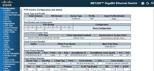
This option allows you to inspect and configure the current PTP clock settings.
-
Clock Instance: Indicates the instance number of a particular Clock Instance [0..3].
-
HW Domain: Indicates the HW clock domain used by the clock.
-
Device Type: Indicates the Type of the Clock Instance. There are five Device Types. -
Profile: Indicates the profile used by the clock.
-
Apply Profile Defaults: If the clock has been configured to use a profile, clicking the Apply button will reset configured values to profile defaults.
-
Steps Removed (stpRm): It is the number of PTP clocks traversed from the grandmaster to the local slave clock.
-
Offset From Master: Time difference between the master clock and the local slave clock, measured in ns.
-
Mean Path Delay: The mean propagation time for the link between the master and the local slave.
-
Parent Port ID: Clock identity for the parent clock. If the local clock is not a slave, the value is the clock's own id.
-
Port: Port Id for the parent master port.
-
PStat: Parent's Stats (always False).
-
Var: It is observed parent offset scaled log variance.
-
Rate: Observed Parent Clock Phase Change Rate that is, the slave clocks rate offset compared to the master. (unit = ns per s).
-
GrandMaster ID: Clock identity for the grand master clock. If the local clock is not a slave, the value is the clock's own id.
-
GrandMaster Clock Quality: The clock quality announced by the grand master (See the description of Clock Default DataSet: Clock Quality).
-
Pri1: Clock priority 1 announced by the grand master.
-
Pri2: Clock priority 2 announced by the grand master.
-
Device Type: Indicates the Type of the Clock Instance. There are five Device Types. -
2 Step Flag: True if two-step Sync events and Pdelay_Resp events are used.
-
One-Way: If True, one way measurements are used. This parameter applies only to a slave. In one-way mode no delay measurements are performed, that is, this is applicable only if frequency synchronization is needed. The master always responds to delay requests.
-
Ports: The total number of physical ports in the node.
-
Clock Identity: It shows unique clock identifier.
-
Dom: Clock domain [0..127].
-
Clock Quality: The clock quality is determined by the system, and holds three parts: Clock Class, Clock Accuracy and OffsetScaledLog Variance as defined in IEEE1588.The Clock Accuracy values are defined in IEEE1588 table 6 (Currently, the clock Accuracy is set to 'Unknown' as default).
-
Pri1: Clock priority 1 [0..255] used by the BMC master select algorithm
-
Pri2: Clock priority 2 [0..255] used by the BMC master select algorithm.
-
Protocol: Transport protocol used by the PTP protocol engine. The following values are possible: -
VLAN Tag Enable: The VLAN Tag Enable parameter is ignored, because the tagging is controlled by the VLAN configuration.
-
VID: VLAN Identifier used for tagging the VLAN packets.
-
PCP: Priority Code Point value used for PTP frames.
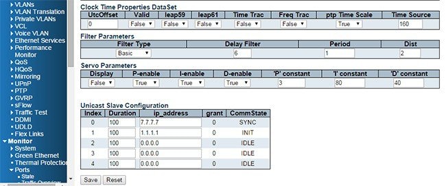
Filter Parameters: The default delay filter is a low pass filter, with a time constant of 2**Delay Filter*DelayRequestRate.
 Note | In configurations with Timestamp enabled PHYs, the period is automatically increased, if period*dist < SyncPackets per sec/4, that is, max four adjustments are made per sec. |
Servo Parameters: The default clock servo uses a PID regulator to calculate the current clock rate that is,
clockAdjustment =
OffsetFromMaster/ P constant +
Integral(OffsetFromMaster)/ I constant +
-
Display: If True, then Offset From Master, MeanPathDelay and clockAdjustment are logged on the debug terminal.
-
P-enable: If True, the P part of the algorithm is included.
-
I-enable: If True, the I part of the algorithm is included.
-
D-enable: If True, the D part of the algorithm is included.
-
'P' constant: [1..1000] See above.
-
'I' constant: [1..1000] See above.
-
'D' constant: [1..1000] See above.
-
Duration: The number of seconds a master is requested to send Announce/Sync messages. The request is repeated from the slave each Duration/4 seconds.
-
ip_address: IPv4 Address of the Master clock.
- grant: The granted repetition period for the sync message.
-
CommState: The state of the communication with the master, possible values are:
PTP Clock's Port Configuration
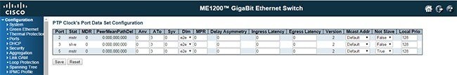
The port data set is defined in the IEEE 1588 Standard. It holds three groups of data: the static members, the dynamic members, and configurable members which can be set here.
-
Port: Static member port Identity. Port number [1..max port no].
-
Stat: Dynamic member port State. Current state of the port.
-
MDR: Dynamic member log Min Delay Req Interval. The delay request interval announced by the master.
-
PeerMeanPathDel: The path delay measured by the port in P2P mode. In E2E mode this value is 0.
-
Anv: The interval for issuing announce messages in master state. Range is -3 to 4.
-
ATo: The timeout for receiving announce messages on the port. Range is 1 to 10.
-
Syv: The interval for issuing sync messages in master. Range is -7 to 4.
-
Configurable member delay mechanism (Dlm): The delay mechanism used for the port. Possible values are: Can be defined per port in an Ordinary or Boundary clock. In a transparent clock all ports use the same delay mechanism, determined by the clock type.
-
MPR: The interval for issuing Delay_Req messages for the port in e2e mode. This value is announced from the master to the slave in an announce message. The value is reflected in the MDR field in the Slave. The interval for issuing Pdelay_Req messages for the port in P2P mode.
Note
The interpretation of this parameter has changed from release 2.40. In earlier versions, the value was interpreted relative to the Sync interval, this was a violation of the standard, so now the value is interpreted as an interval that is, MPR = 0 => 1 Delay_Req pr sec, independent of the Sync rate. Range is -7 to 5.
-
Delay Asymmetry: If the transmission delay for a link in not symmetric, the asymmetry can be configured here, see IEEE 1588 Section 7.4.2 Communication path asymmetry. Range is -100000 to 100000.
-
Ingress latency: Ingress latency measured in ns, as defined in IEEE 1588 Section 7.3.4.2. Range is -100000 to 100000.
-
Egress Latency: Egress latency measured in ns, as defined in IEEE 1588 Section 7.3.4.2. Range is -100000 to 100000.
-
Version: The current implementation only supports PTP version 2.
 Feedback