- Preface
- Basic Functionality
- Basic Configurations
- Configuring System
- Configuring Green Ethernet
- Configuring Thermal Protection
- Configuring Ports
- Configuring Security
- Configuring Aggregation
- Configuring Link OAM
- Configuring Loop Protection
- Configuring Spanning Tree
- Configuring MVR
- Configuring LLDP
- Configuring SyncE
- Configuring EPS
- Configuring MEP
- Configuring ERPS
- Configuring MAC Table
- Configuring VLANs
- Configuring VLAN Translation
- Configuring Ethernet Services
- Configuring Performance Monitor
- Configuring QoS
- Configuring HQoS
- Configuring Mirroring
- Configuring PTP
- Configuring sFlow
- Configuring Traffic Test
- Configuring Traffic Test Loops
- Configuring DDMI
- Configuring UDLD
- Configuring Flex Links
- Monitoring System
- Monitoring Green Ethernet
- Monitoring Thermal Protection
- Monitoring Ports
- Monitoring Link OAM
- Monitoring Security
- Monitoring Aggregation
- Monitoring Loop Protection
- Monitoring Spanning Tree
- Monitoring MVR
- Monitoring LLDP
- Monitoring Ethernet Services
- Monitoring Performance Monitor
- Monitoring PTP
- Monitoring MAC Table
- Monitoring VLANs
- Monitoring sFlow
- Monitoring DDMI
- Monitoring UDLD
- Monitoring Flex Links
- Diagnostics
- Maintenance
- Use Cases
Use Cases
This section presents a few essential use cases for configuring in the ME 1200 Cisco Ethernet Switch Web GUI Interface.
Configuring Y.1731
This use case describes the flow of configurations that are required to configure the Y.1731 feature in the Cisco ME 1200 Web GUI Interface.
- Prerequisites for ITU-T Y.1731 Performance Monitoring In a Service Provider Network
- Steps to Configure Y1731
Prerequisites for ITU-T Y.1731 Performance Monitoring In a Service Provider Network

Steps to Configure Y1731
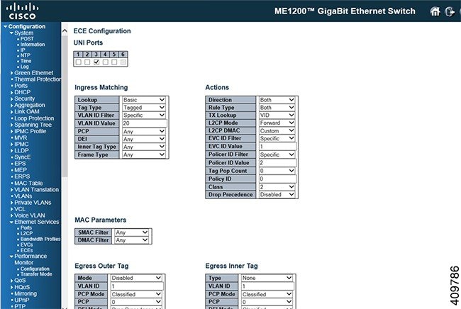
| Step 1 | To configure
ECE, click
. For more information,
ECE Control List Configuration.
 |
| Step 2 | To configure
EVC, click
. For more information, see
EVC Port Configuration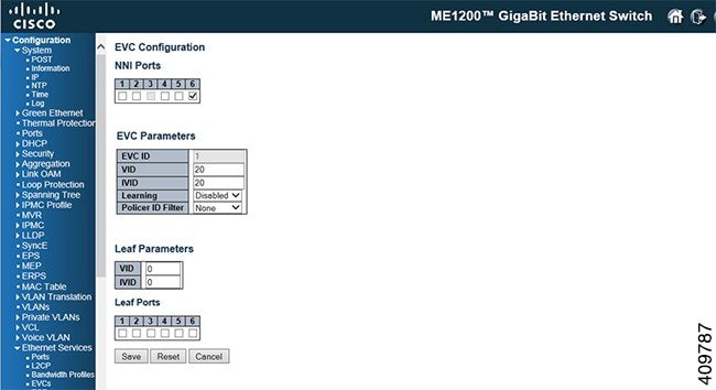 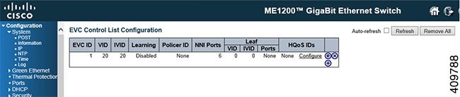 |
| Step 3 | To configure
MEP, click
. For more information, see
Maintenance Entity Point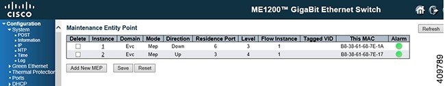 |
| Step 4 | Click on the
instance number which is created in the above step to configure MEP
parameters.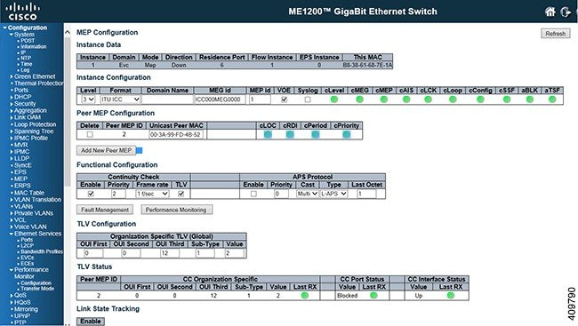 |
| Step 5 | To configure the
Performance Monitoring session and storage, click
. This enables the
session and storage parameters which stores session data in the RAM storage
data in the flash respectively. For more information, see
Performance Monitor Configuration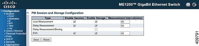 |
| Step 6 | To transfer
performance monitoring data to a tftp/http server, click
. For more information, see
Performance Monitor Transfer Configuration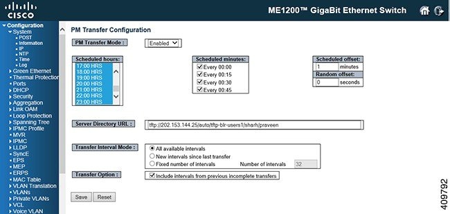 |
| Step 7 | To enable
Performance Monitoring, click
. For more
information, see
Maintenance Entity Point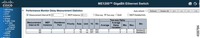 |
| Step 8 | To enable Fault
Management, click
For more information,
see
Maintenance Entity Point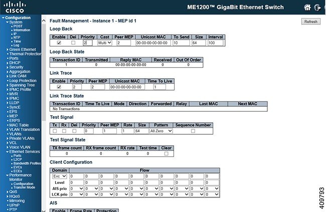 |
Configuring RFC2544
This use case describes the flow of configurations that are required to configure the RFC2544 feature in the Cisco ME 1200 Web GUI Interface.
Steps to Configure RFC2544
| Step 1 | To configure
RFC2544, click
. This option provides an
overview of the defined profiles along with options for editing and deleting
them and creating new one. For more information,
RFC2544 Profile Overview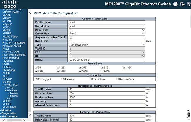 |
| Step 2 | To disable Port
3 in STP, click
. The STP option allows you
to inspect the current STP CIST port configurations and change them. For more
information, see
STP CIST Port Configuration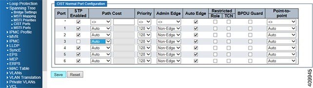 |
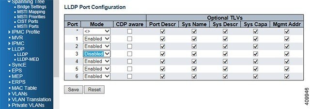
| Step 3 | To disable LLDP
on Port 3, click
. The LLDP option allows you to inspect
and configure the current LLDP port settings. For more information, see
LLDP Configuration
 |
| Step 4 | To configure
VLAN settings, click
. For more information on configuring
VLANs, see
VLAN Configuration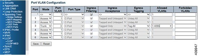 |
| Step 5 | To execute a
test run of RFC2455 configuration, click
. For more information, see
RFC2544 Report Overview
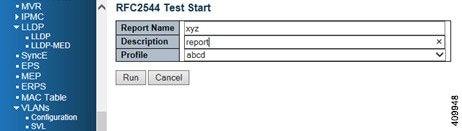 |
| Step 6 | To configure on
a remote nid to Loop, click
. For more information, see
TT-LOOP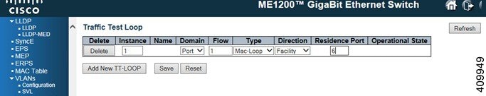 |
| Step 7 | The loopback
must be enabled in the remote end and port should be
Active. For more information, see
Maintenance Entity Point
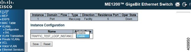 |
 Feedback