- Preface
- Basic Functionality
- Basic Configurations
- Configuring System
- Configuring Green Ethernet
- Configuring Thermal Protection
- Configuring Ports
- Configuring Security
- Configuring Aggregation
- Configuring Link OAM
- Configuring Loop Protection
- Configuring Spanning Tree
- Configuring MVR
- Configuring LLDP
- Configuring SyncE
- Configuring EPS
- Configuring MEP
- Configuring ERPS
- Configuring MAC Table
- Configuring VLANs
- Configuring VLAN Translation
- Configuring Ethernet Services
- Configuring Performance Monitor
- Configuring QoS
- Configuring HQoS
- Configuring Mirroring
- Configuring PTP
- Configuring sFlow
- Configuring Traffic Test
- Configuring Traffic Test Loops
- Configuring DDMI
- Configuring UDLD
- Configuring Flex Links
- Monitoring System
- Monitoring Green Ethernet
- Monitoring Thermal Protection
- Monitoring Ports
- Monitoring Link OAM
- Monitoring Security
- Monitoring Aggregation
- Monitoring Loop Protection
- Monitoring Spanning Tree
- Monitoring MVR
- Monitoring LLDP
- Monitoring Ethernet Services
- Monitoring Performance Monitor
- Monitoring PTP
- Monitoring MAC Table
- Monitoring VLANs
- Monitoring sFlow
- Monitoring DDMI
- Monitoring UDLD
- Monitoring Flex Links
- Diagnostics
- Maintenance
- Use Cases
Monitoring
LLDP
The LLDP feature available on the ME 1200 Web GUI allows you to monitor the LLDP parameters, LLDP port, and LLDP Media.
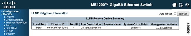
LLDP Neighbor
This option provides a
status overview for all LLDP neighbors. The displayed table contains a row for
each port on which an LLDP neighbor is detected.
-
Local Port: The port on which the LLDP frame was received.
-
Chassis ID: The Chassis ID is the identification of the neighbor's LLDP frames.
-
Port ID: The Port ID is the identification of the neighbor port.
-
Port Description: Port Description is the port description advertised by the neighbor unit.
-
System Name: System Name is the name advertised by the neighbor unit.
-
System Capabilities: System Capabilities describes the neighbor unit's capabilities. The possible capabilities are:
-
Management Address: Management Address is the neighbor unit's address that is used for higher layer entities to assist discovery by the network management. This could for instance hold the neighbor's IP address.
LLDP-MED Neighbor Information
This option provides a
status overview of all LLDP-MED neighbors. The displayed table contains a row
for each port on which an LLDP neighbor is detected.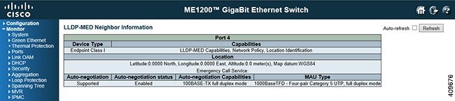
-
Port: The port on which the LLDP frame was received.
-
Device Type: LLDP-MED Devices are comprised of two primary Device Types - Network Connectivity Devices and Endpoint Devices.
LLDP-MED Network Connectivity Device Definition
LLDP-MED Network Connectivity Devices, as defined in TIA-1057, provide access to the IEEE 802 based LAN infrastructure for LLDP-MED Endpoint Devices. An LLDP-MED Network Connectivity Device is a LAN access device based on any of the following technologies: LLDP-MED Endpoint Device Definition
LLDP-MED Endpoint Devices, as defined in TIA-1057, are located at the IEEE 802 LAN network edge, and participate in IP communication service using the LLDP-MED framework. Within the LLDP-MED Endpoint Device category, the LLDP-MED scheme is broken into further Endpoint Device Classes, as defined in the following.
Each LLDP-MED Endpoint Device Class is defined to build upon the capabilities defined for the previous Endpoint Device Class. For-example will any LLDP-MED Endpoint Device claiming compliance as a Media Endpoint (Class II) also support all aspects of TIA-1057 applicable to Generic Endpoints (Class I), and any LLDP-MED Endpoint Device claiming compliance as a Communication Device (Class III) will also support all aspects of TIA-1057 applicable to both Media Endpoints (Class II) and Generic Endpoints (Class I).
LLDP-MED Generic Endpoint (Class I)
The LLDP-MED Generic Endpoint (Class I) definition is applicable to all endpoint products that require the base LLDP discovery services defined in TIA-1057, however do not support IP media or act as an end-user communication appliance. Such devices may include (but are not limited to) IP Communication Controllers, other communication related servers, or any device requiring basic services as defined in TIA-1057.
Discovery services defined in this class include LAN configuration, device location, network policy, power management, and inventory management.
LLDP-MED Media Endpoint (Class II)
The LLDP-MED Generic Endpoint (Class I) definition is applicable to all endpoint products that require the base LLDP discovery services defined in TIA-1057, however do not support IP media or act as an end-user communication appliance. Such devices may include (but are not limited to) IP Communication Controllers, other communication related servers, or any device requiring basic services as defined in TIA-1057.
Discovery services defined in this class include LAN configuration, device location, network policy, power management, and inventory management.
LLDP-MED Communication Endpoint (Class III)
The LLDP-MED Communication Endpoint (Class III) definition is applicable to all endpoint products that act as end user communication appliances supporting IP media. Capabilities include all of the capabilities defined for the previous Generic Endpoint (Class I) and Media Endpoint (Class II) classes, and are extended to include aspects related to end user devices. Example product categories expected to adhere to this class include (but are not limited to) end user communication appliances, such as IP Phones, PC-based softphones, or other communication appliances that directly support the end user.
Discovery services defined in this class include provision of location identifier (including ECS / E911 information), embedded L2 switch support, inventory management.
-
LLDP-MED Capabilities: LLDP-MED Capabilities describes the neighbor unit's LLDP-MED capabilities. The possible capabilities are: -
Application Type: Application Type indicating the primary function of the application(s) defined for this network policy, advertised by an Endpoint or Network Connectivity Device. The possible application types are shown below.
-
Voice - for use by dedicated IP Telephony handsets and other similar appliances supporting interactive voice services. These devices are typically deployed on a separate VLAN for ease of deployment and enhanced security by isolation from data applications.
-
Voice Signalling - for use in network topologies that require a different policy for the voice signalling than for the voice media.
-
Guest Voice - to support a separate limited feature-set voice service for guest users and visitors with their own IP Telephony handsets and other similar appliances supporting interactive voice services.
-
Guest Voice Signalling - for use in network topologies that require a different policy for the guest voice signalling than for the guest voice media.
-
Softphone Voice - for use by softphone applications on typical data centric devices, such as PCs or laptops.
-
Video Conferencing - for use by dedicated Video Conferencing equipment and other similar appliances supporting real-time interactive video/audio services.
-
Streaming Video - for use by broadcast or multicast based video content distribution and other similar applications supporting streaming video services that require specific network policy treatment. Video applications relying on TCP with buffering would not be an intended use of this application type.
- Video Signalling - for use in network topologies that require a separate policy for the video signalling than for the video media.
-
-
Policy: Policy indicates that an Endpoint Device wants to explicitly advertise that the policy is required by the device. Can be either Defined or Unknown. -
TAG: TAG is indicative of whether the specified application type is using a tagged or an untagged VLAN. Can be Tagged or Untagged.
-
VLAN ID: VLAN ID is the VLAN identifier (VID) for the port as defined in IEEE 802.1Q-2003. A value of 1 through 4094 is used to define a valid VLAN ID. A value of 0 (Priority Tagged) is used if the device is using priority tagged frames as defined by IEEE 802.1Q-2003, meaning that only the IEEE 802.1D priority level is significant and the default PVID of the ingress port is used instead.
-
Priority: Priority is the Layer 2 priority to be used for the specified application type. One of the eight priority levels (0 through 7).
-
DSCP: DSCP is the DSCP value to be used to provide Diffserv node behavior for the specified application type as defined in IETF RFC 2474. Contain one of 64 code point values (0 through 63).
-
Auto-negotiation: Auto-negotiation identifies if MAC/PHY auto-negotiation is supported by the link partner.
-
Auto-negotiation status: Auto-negotiation status identifies if auto-negotiation is currently enabled at the link partner. If Auto-negotiation is supported and Auto-negotiation status is disabled, the 802.3 PMD operating mode will be determined the operational MAU type field value rather than by auto-negotiation.
-
Auto-negotiation Capabilities: Auto-negotiation Capabilities shows the link partners MAC/PHY capabilities.
LLDP Neighbors EEE Information
By using EEE, power savings can be achieved at the expense of traffic latency. Due to that the circuits EEE turn off to save power, need time to boot up before sending traffic over the link. This time is called wakeup time. To achieve minimal latency, devices can use LLDP to exchange information about their respective tx and rx wakeup time, as a way to agree upon the minimum wakeup time they need.
This option provides
an overview of EEE information exchanged by LLDP.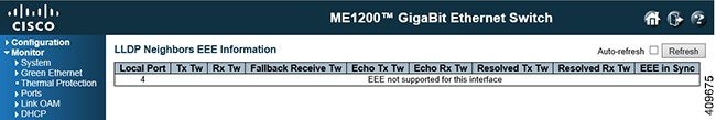
The displayed table contains a row for each port. If the port does not supports EEE, then it displays as EEE not supported for this interface.
If EEE is not enabled on particular interface, then it displays as EEE not enabled for this interface.
If the link partner does not supports EEE, then it displays as Link partner is not EEE capable.
-
Local Port: The port on which LLDP frames are received or transmitted.
-
Tx Tw: The link partner's maximum time that transmit path can hold-off sending data after deassertion of LPI.
-
Rx Tw: The link partner's time that receiver would like the transmitter to hold-off to allow time for the receiver to wake from sleep.
-
Fallback Receive Tw: The link partner's fallback receive Tw.
A receiving link partner may inform the transmitter of an alternate desired Tw_sys_tx. Since a receiving link partner is likely to have discrete levels for savings, this provides the transmitter with additional information that it may use for a more efficient allocation. Systems that do not implement this option default the value to be the same as that of the Receive Tw_sys_tx.
-
Echo Tx Tw: The link partner's Echo Tx Tw value.
The respective echo values shall be defined as the local link partners reflection (echo) of the remote link partners respective values. When a local link partner receives its echoed values from the remote link partner it can determine whether or not the remote link partner has received, registered and processed its most recent values. For example, if the local link partner receives echoed parameters that do not match the values in its local MIB, then the local link partner infers that the remote link partners request was based on stale information.
-
Echo Rx Tw: The link partner's Echo Rx Tw value.
-
Resolved Tx Tw: The resolved Tx Tw for this link. Note : NOT the link partner.
The resolved value that is the actual "tx wakeup time " used for this link (based on EEE information exchanged via LLDP).
-
Resolved Rx Tw: The resolved Rx Tw for this link. Note : NOT the link partner.
The resolved value that is the actual tx wakeup time used for this link (based on EEE information exchanged via LLDP).
-
EEE in Sync: Shows whether the switch and the link partner have agreed on wake times.
LLDP Statistics
This option provides
an overview of all LLDP traffic. Two types of counters are exist. Global
counters are counters that refer to the whole switch, while local counters
refer to per port counters for the currently selected switch.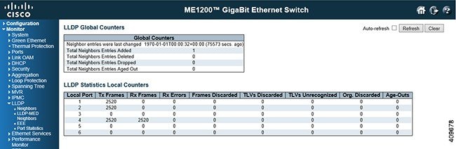
Global Counters
-
Total Neighbors Entries Added: Shows the number of new entries added since switch reboot.
-
Total Neighbors Entries Deleted: Shows the number of new entries deleted since switch reboot.
-
Total Neighbors Entries Dropped: Shows the number of LLDP frames dropped due to the entry table being full.
-
Total Neighbors Entries Aged Out: Shows the number of entries deleted due to Time-To-Live expiring.
Local Counters
-
Local Port: The port on which LLDP frames are received or transmitted.
-
Tx Frames: The number of LLDP frames transmitted on the port.
-
Rx Frames: The number of LLDP frames received on the port.
-
Rx Errors: The number of received LLDP frames containing some kind of error.
-
Frames Discarded: If a LLDP frame is received on a port, and the switch's internal table has run full, the LLDP frame is counted and discarded. This situation is known as Too Many Neighbors in the LLDP standard. LLDP frames require a new entry in the table when the Chassis ID or Remote Port ID is not already contained within the table. Entries are remove from the table when a given port's link is down, an LLDP shutdown frame is received, or when the entry ages out.
-
TLVs Discarded: Each LLDP frame can contain multiple pieces of information, known as TLVs (TLV is short for "Type Length Value"). If a TLV is malformed, it is counted and discarded.
-
TLVs Unrecognized: The number of well-formed TLVs, but with an unknown type value.
-
Org. Discarded: If LLDP frame is received with an organizationally TLV, but the TLV is not supported the TLV is discarded and counted.
-
Age-Outs: Each LLDP frame contains information about how long time the LLDP information is valid (age-out time). If no new LLDP frame is received within the age out time, the LLDP information is removed, and the Age-Out counter is incremented.
 Feedback