- Preface
- Basic Functionality
- Basic Configurations
- Configuring System
- Configuring Green Ethernet
- Configuring Thermal Protection
- Configuring Ports
- Configuring Security
- Configuring Aggregation
- Configuring Link OAM
- Configuring Loop Protection
- Configuring Spanning Tree
- Configuring MVR
- Configuring LLDP
- Configuring SyncE
- Configuring EPS
- Configuring MEP
- Configuring ERPS
- Configuring MAC Table
- Configuring VLANs
- Configuring VLAN Translation
- Configuring Ethernet Services
- Configuring Performance Monitor
- Configuring QoS
- Configuring HQoS
- Configuring Mirroring
- Configuring PTP
- Configuring sFlow
- Configuring Traffic Test
- Configuring Traffic Test Loops
- Configuring DDMI
- Configuring UDLD
- Configuring Flex Links
- Monitoring System
- Monitoring Green Ethernet
- Monitoring Thermal Protection
- Monitoring Ports
- Monitoring Link OAM
- Monitoring Security
- Monitoring Aggregation
- Monitoring Loop Protection
- Monitoring Spanning Tree
- Monitoring MVR
- Monitoring LLDP
- Monitoring Ethernet Services
- Monitoring Performance Monitor
- Monitoring PTP
- Monitoring MAC Table
- Monitoring VLANs
- Monitoring sFlow
- Monitoring DDMI
- Monitoring UDLD
- Monitoring Flex Links
- Diagnostics
- Maintenance
- Use Cases
Configuring Ethernet
Services
The Ethernet Services feature available on the ME 1200 Web GUI allows you to configure the EVC port, EVC L2CP, EVC bandwidth, and EVC Control List.
- EVC Port Configuration
- EVC L2CP Configuration
- EVC Bandwidth Profile Configuration
- EVC Control List Configuration
- ECE Control List Configuration
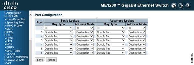
EVC Port Configuration
-
Port: The logical port for the settings contained in the same row.
-
Basic Key Type: The key type specifying the key generated for frames received on the port. The allowed values are: -
Normal: Half key, matches outer tag, SIP/DIP and SMAC/DMAC.
-
Double Tag: Quarter key, matches inner and outer tag.
-
IP Address: Half key, matches inner and outer tag, SIP and DIP. For non-IP frames, match outer tag only.
-
MAC and IP Address: Full key, matches inner and outer tag, SMAC, DMAC, SIP, and DIP.
Filtering on DMAC type (unicast or multicast or broadcast) is supported for any key type.
-
-
Basic Address Mode: The IP/MAC address mode that specifies whether the EVC classification must be based on source (SMAC/SIP) or destination (DMAC/DIP) addresses. This parameter is only used when the key type is Normal. The allowed values are: -
Advanced Key Type: The advanced key type specifying the key generated for the second lookup. The allowed values are: -
Normal: Half key, match outer tag, SIP/DIP and SMAC/DMAC.
-
Double Tag: Quarter key, match inner and outer tag.
-
IP Address: Half key, match inner and outer tag, SIP, and DIP. For non-IP frames, match outer tag only.
-
MAC and IP Address: Full key, match inner and outer tag, SMAC, DMAC, SIP and DIP.
Filtering on DMAC type (unicast/multicast/broadcast) is supported for any key type.
-
-
Advanced Address Mode: The advanced IP/MAC address mode specifying for the second lookup. This parameter is only used when the key type is Normal. The allowed values are:
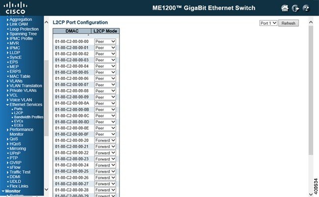
EVC L2CP Configuration
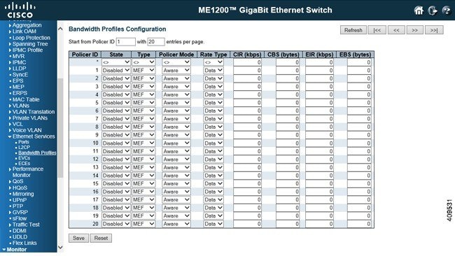
EVC Bandwidth Profile Configuration
-
Start Policer ID: The start Policer ID for displaying the table entries. The allowed range is from 1 through 1022.
-
Number of Entries: The number of entries per page. The allowed range is from 2 through 1022.
-
Policer ID: The Policer ID is used to identify one of the 1022 policers.
-
State: The administrative state of the bandwidth profile. The allowed values are: -
Type: The policer type of the bandwidth profile. The allowed values are: -
Policer Mode: The color mode of the bandwidth profile. The allowed values are: -
Rate Type: The rate type of the bandwidth profile. The allowed values are: -
CIR: The Committed Information Rate of the bandwidth profile. The allowed range is from 0 through 10000000 kilobit per second.
-
CBS: The Committed Burst Size of the bandwidth profile. The allowed range is from 0 through 100000 bytes.
-
EIR: The Excess Information Rate for MEF type bandwidth profile. The allowed range is from 0 through 10000000 kilobit per second.
-
EBS: The Excess Burst Size for MEF type bandwidth profile. The allowed range is from 0 through 100000 bytes.
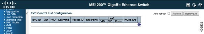
EVC Control List Configuration
-
EVC ID: The EVC ID identifies the EVC. The range is from 1 through 1024.
-
VID: The VLAN ID in the PB network. It may be inserted in a C-tag, S-tag, or S-custom tag depending on the NNI port VLAN configuration. The range is from 0 through 4095.
-
IVID: The internal or classified VLAN ID in the PB network. The range is from 1 through 4095
-
Learning: The learning mode for the EVC controls whether source MAC addresses are learned for frames matching the EVC. Learning may be disabled if the EVC only includes two UNI or NNI ports. The possible values are: -
Policer ID: The ingress bandwidth profile mode for the EVC. The possible values are: -
NNI Ports: The list of Network to Network Interfaces for the EVC.
-
Leaf VID: The leaf VLAN ID used in the outer tag for the EVC.
-
Leaf IVID: The leaf internal classified VLAN ID for the EVC.
-
Leaf Ports: The list of leaf ports for the EVC.
-
HQoS IDs: The list of HQoS entries mapped to the EVC ports and a link to configure the mappings.
-
Modification icons: You can modify each EVC in the table using the following icons:
ECE Control List Configuration
This option displays the current EVC Control Entries (ECEs). The settings can also be configured here.
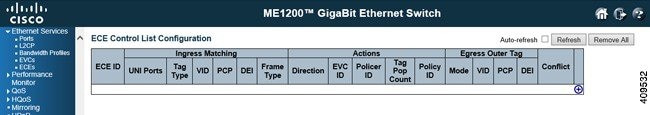
ECE ID: The ECE ID identifies the ECE. Unique ECE IDs are automatically assigned to ECEs added. The range is from 1 through 1024.
-
UNI Ports: The list of User Network Interfaces for the ECE.
-
Tag Type: The tag type for the ECE. The possible values are:
-
VID: The VLAN ID for the ECE. It is only significant if the tag type Tagged is selected. The possible values are: -
PCP: The PCP value for the ECE. It is only significant if the tag type Tagged is selected. The possible values are: -
DEI: The DEI value for the ECE. It is only significant if the tag type Tagged is selected. The possible values are: 0, 1, or Any.
-
Frame Type: The frame type for the ECE. The possible values are:
-
Outer Tag Mode: The outer tag for nni-to-uni direction for the ECE. The possible values are:
-
Outer Tag VID: The EVC outer tag VID for UNI ports. The range is from 0 through 4095.
-
Outer Tag PCP: The outer tag PCP mode for the ECE. The possible values are:
-
Outer Tag DEI: The outer tag DEI mode for the ECE. The possible values are:
-
Conflict: Indicates the hardware status of the specific ECE. The specific ECE is not applied to the hardware due to hardware limitations.
-
Modification icons: You can modify each EVC Control Entry (ECE) in the table using the following icons:
-
Insert new ECE before this ECE icon: Inserts a new ECE before the current row.
-
Edit ECE icon: Edits the ECE row.
-
Move ECE up icon: Moves the ECE up the list.
-
Move ECE down icon: Moves the ECE down the list.
-
Delete ECE icon: Deletes the ECE.
-
Add ECE to end of list icon: The lowest plus sign adds a new entry at the bottom of the ECE listings.
-
 Feedback