- Preface
- Basic Functionality
- Basic Configurations
- Configuring System
- Configuring Green Ethernet
- Configuring Thermal Protection
- Configuring Ports
- Configuring Security
- Configuring Aggregation
- Configuring Link OAM
- Configuring Loop Protection
- Configuring Spanning Tree
- Configuring MVR
- Configuring LLDP
- Configuring SyncE
- Configuring EPS
- Configuring MEP
- Configuring ERPS
- Configuring MAC Table
- Configuring VLANs
- Configuring VLAN Translation
- Configuring Ethernet Services
- Configuring Performance Monitor
- Configuring QoS
- Configuring HQoS
- Configuring Mirroring
- Configuring PTP
- Configuring sFlow
- Configuring Traffic Test
- Configuring Traffic Test Loops
- Configuring DDMI
- Configuring UDLD
- Configuring Flex Links
- Monitoring System
- Monitoring Green Ethernet
- Monitoring Thermal Protection
- Monitoring Ports
- Monitoring Link OAM
- Monitoring Security
- Monitoring Aggregation
- Monitoring Loop Protection
- Monitoring Spanning Tree
- Monitoring MVR
- Monitoring LLDP
- Monitoring Ethernet Services
- Monitoring Performance Monitor
- Monitoring PTP
- Monitoring MAC Table
- Monitoring VLANs
- Monitoring sFlow
- Monitoring DDMI
- Monitoring UDLD
- Monitoring Flex Links
- Diagnostics
- Maintenance
- Use Cases
Configuring
ERPS
ERPS
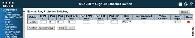
The ERPS instances can be configured here.
-
Delete: This check box is used to mark an ERPS for deletion in the next Save operation.
-
ERPS ID: The ID of the created Protection group, It must be an integer value between 1 and 64. The maximum number of ERPS Protection Groups that can be created are 64. Click the ID of a Protection group to enter the configuration page.
-
Port 0: This will create a Port 0 of the switch in the Ring.
-
Port 1: This will create Port 1 of the switch in the Ring. As interconnected sub-ring will have only one ring port, "Port 1" is configured as "0" for interconnected sub-ring. "0" in this field indicates that no "Port 1" is associated with this instance.
-
Port 0 SF MEP: The Port 0 Signal Fail reporting MEP.
-
Port 1 SF MEP: The Port 1 Signal Fail reporting MEP. As only one SF MEP is associated with interconnected sub-ring without virtual channel, it is configured as "0" for such ring instances. "0" in this field indicates that no Port 1 SF MEP is associated with this instance.
-
Port 0 APS MEP: The Port 0 APS PDU handling MEP.
-
Port 1 APS MEP: The Port 1 APS PDU handling MEP. As only one APS MEP is associated with interconnected sub-ring without virtual channel, it is configured as "0" for such ring instances. "0" in this field indicates that no Port 1 APS MEP is associated with this instance.
-
Ring Type: Type of Protecting ring. It can be either major ring or sub-ring.
- Interconnected Node: Interconnected Node indicates that the ring instance is interconnected. Check the check box to configure this. "Yes" indicates it is an interconnected node for this instance. "No" indicates that the configured instance is not interconnected.
-
Virtual Channel: Sub-rings can either have or not have a virtual channel on the interconnected node. This is configured using the Virtual Channel check box. "Yes" indicates it is a sub-ring with virtual channel. "No" indicates, sub-ring does not have a virtual channel.
-
Major Ring ID: Major ring group ID for the interconnected sub-ring. It is used to send topology change updates on major ring. If ring is major, this value is same as the protection group ID of this ring.
-
Alarm: There is an active alarm on the ERPS.
ERPS Configuration for an Instance
This option allows you to inspect and configure the current ERPS instance.
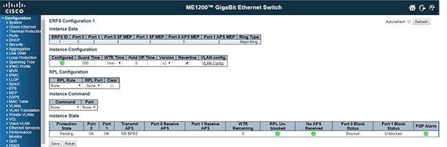
Instance Data: For a description of all the fields displayed here, see ERPS.
-
Configured -
Guard Time: Guard timeout value to be used to prevent ring nodes from receiving outdated R-APS messages.
The period of the guard timer can be configured in 10 ms steps between 10 ms and 2 seconds, with a default value of 500 ms.
-
WTR Time: The Wait To Restore timing value to be used in revertive switching.
The period of the WTR time can be configured by the operator in 1 minute steps between 5 and 12 minutes with a default value of 5 minutes.
-
Hold Off Time: The timing value to be used to make persistent check on Signal Fail before switching.
The range of the hold off timer is 0 to 10 seconds in steps of 100 ms.
-
Version: ERPS Protocol Version - v1 or v2.
-
Revertive: In Revertive mode, after the conditions causing a protection switch has cleared, the traffic channel is restored to the working transport entity, that is, blocked on the RPL.
In Non-Revertive mode, the traffic channel continues to use the RPL, if it is not failed, after a protection switch condition has cleared.
-
VLAN config: VLAN configuration of the Protection Group. Click the VLAN Config link to configure VLANs for this protection group.
-
Command: Administrative command. A port can be administratively configured to be in either manual switch or forced switch state. -
Forced Switch: Forced Switch command forces a block on the ring port where the command is issued.
-
Manual Switch: In the absence of a failure or FS, Manual Switch command forces a block on the ring port where the command is issued.
-
Clear: The Clear command is used for clearing an active local administrative command (for example, Forced Switch or Manual Switch).
-
-
Port: Port selection - Port0 or Port1 of the Protection Group on which the command is applied.
-
Protection State: ERPS state according to State Transition Tables in G.8032.
-
Port 0 -
Port 1 -
Transmit APS: The transmitted APS according to State Transition Tables in G.8032.
-
Port 0 Receive APS: The received APS on Port 0 according to State Transition Tables in G.8032.
-
Port 1 Receive APS: The received APS on Port 1 according to State Transition Tables in G.8032.
-
WTR Remaining: Remaining WTR timeout in milliseconds.
-
RPL Un-blocked: APS is received on the working flow.
-
No APS Received: RAPS PDU is not received from the other end.
-
Port 0 Block Status: Block status for Port 0 (Both traffic and R-APS block status). R-APS channel is never blocked on sub-rings without virtual channel.
-
Port 1 Block Status: Block status for Port 1 (Both traffic and R-APS block status). R-APS channel is never blocked on sub-rings without virtual channel.
-
FOP Alarm: Failure of Protocol Defect(FOP) status. If FOP is detected, red LED glows; else green LED glows.
ERPS VLAN Configuration
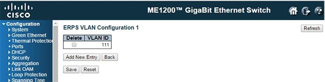
The VLAN is enabled when you click Save. A VLAN without any port members will be deleted when you click Save.
The Delete check box can be used to undo the addition of new VLANs.
 Feedback