- Preface
- Basic Functionality
- Basic Configurations
- Configuring System
- Configuring Green Ethernet
- Configuring Thermal Protection
- Configuring Ports
- Configuring Security
- Configuring Aggregation
- Configuring Link OAM
- Configuring Loop Protection
- Configuring Spanning Tree
- Configuring MVR
- Configuring LLDP
- Configuring SyncE
- Configuring EPS
- Configuring MEP
- Configuring ERPS
- Configuring MAC Table
- Configuring VLANs
- Configuring VLAN Translation
- Configuring Ethernet Services
- Configuring Performance Monitor
- Configuring QoS
- Configuring HQoS
- Configuring Mirroring
- Configuring PTP
- Configuring sFlow
- Configuring Traffic Test
- Configuring Traffic Test Loops
- Configuring DDMI
- Configuring UDLD
- Configuring Flex Links
- Monitoring System
- Monitoring Green Ethernet
- Monitoring Thermal Protection
- Monitoring Ports
- Monitoring Link OAM
- Monitoring Security
- Monitoring Aggregation
- Monitoring Loop Protection
- Monitoring Spanning Tree
- Monitoring MVR
- Monitoring LLDP
- Monitoring Ethernet Services
- Monitoring Performance Monitor
- Monitoring PTP
- Monitoring MAC Table
- Monitoring VLANs
- Monitoring sFlow
- Monitoring DDMI
- Monitoring UDLD
- Monitoring Flex Links
- Diagnostics
- Maintenance
- Use Cases
Monitoring
Performance Monitor
The Performance Monitor feature available on the ME 1200 Web GUI allows you to monitor the Performance Monitor statistics.
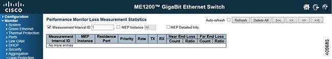
- Performance Monitor Loss Measurement Statistics
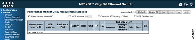
- Performance Monitor Delay Measurement Statistics
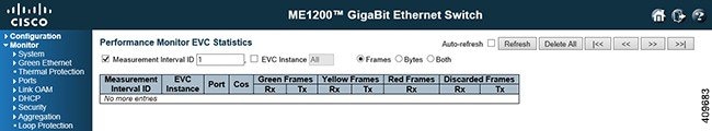
- Performance Monitor EVC Statistics
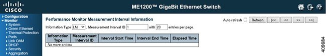
- Performance Monitor Measurement Interval Information
Performance Monitor Loss Measurement Statistics
-
Measurement Interval ID: The measurement interval for the performance monitor data sets.
-
MEP Instance: The MEP instance for the performance monitor data sets.
-
Residence Port: The residence port for the MEP.
-
Priority: The priority to be inserted as PCP bits in TAG (if any).
-
Rate: The gap between transmitting 1DM/DMM PDU in 10 ms. The range is 10 to 65535.
-
Unit: The time resolution.
-
TX: The number of frame transmitted.
-
RX: The number of frame received.
-
One-way Far to Near Average Delay: The one-way far to near average delay.
-
One-way Far to Near Average Delay Variation: The one-way far to near average delay variation.
-
One-way Far to Near Min. Delay: The minimum one-way near to far delay.
-
One-way Far to Near Max. Delay: The maximum one-way near to far delay.
-
One-way Near to Far Average Delay: The number of red received.
-
One-way Near to Far Average Delay Variation: The one-way near to far average delay variation.
-
One-way Near to Far Min. Delay: The minimum one-way near to far delay.
-
One-way Near to Far Max. Delay: The maximum one-way near to far delay.
-
Two-way Delay Average Delay: The two-way average delay.
-
Two-way Average Delay Variation: The two-way average delay variation.
-
Two-way Min. Delay: The minimum two-way delay.
-
Two-way Max. Delay: The maximum two-way delay.
-
Domain
-
Direction
-
Level: The MEG level of this MEP.
-
Flow Instance: The MEP is related to this flow - See Domain.
-
Tagged VID
-
MEP ID: This value will become the transmitted two byte CCM MEP ID.
-
MAC Address: The MAC of this MEP - can be used by other MEP when unicast is selected (Info only).
-
Peer MEP ID: This value will become an expected MEP ID in a received CCM - see cMEP.
-
Peer MAC Address: This MAC will be used when unicast is selected with this peer MEP. Also this MAC is used to create HW checking of receiving CCM PDU (LOC detection) from this MEP.
-
Bin: A Measurement Bin is a counter that stores the number of delay measurements falling within a specified range, during a Measurement Interval.
If the measurement threshold is 5000 microseconds and the total number of Measurement Bins is four, we can give an example as follows: Bin Threshold Range bin0
0 microsecond
0 microsecond <= measurement < 5,000 microseconds
bin1
5,000 microseconds
5,000 microseconds <= measurement < microseconds
bin2
10,000 microseconds
10,000 microseconds <= measurement < 15,000 microseconds
bin3
15,000 microseconds
15,000 microseconds <= measurement < infinite microseconds
Performance Monitor Delay Measurement Statistics
-
Measurement Interval ID: The measurement interval for the performance monitor data sets.
-
MEP Instance: The MEP instance for the performance monitor data sets.
-
Residence Port: The residence port for the MEP.
-
Priority: The priority to be inserted as PCP bits in TAG (if any).
-
Rate: Selected the frame rate of CCM/LMM PDU. This is the inverse of transmission period as described in Y.1731.
-
TX: The number of frame transmitted. RXThe number of frame received.
-
Near End Loss Count: The near end loss count.
-
Near End Loss Ratio: The near end loss ratio.
-
Far End Loss Count: The far end loss count.
-
Far End Loss Ratio: The far end loss ratio.
-
Domain
-
Direction
-
Level: The MEG level of this MEP.
-
Flow Instance: The MEP is related to this flow - See Domain.
-
Tagged VID -
MEP ID: This value will become the transmitted two byte CCM MEP ID.
-
MAC Address: The MAC of this MEP - can be used by other MEP when unicast is selected (Info only).
Performance Monitor EVC Statistics
-
Measurement Interval ID: The measurement interval for the performance monitor data sets.
-
EVC Instance: The EVC instance for the performance monitor data sets.
-
MEP Instance: The MEP instance for the performance monitor data sets.
-
Residence Port: The residence port for the EVC.
-
Cos -
Rx Green Frames: The number of green received.
-
Tx Green Frames: The number of green transmitted.
-
Rx Yellow Frames: The number of yellow received.
-
Tx Yellow Frames: The number of yellow transmitted.
-
Rx Red Frames: The number of red received.
-
Rx Discarded Frames: The number of discarded in the ingress queue system.
-
Tx Discarded Frames: The number of discarded in the egress queue system.
-
Frames: Show frames statistics only.
-
Bytes: Show bytes statistics only.
-
Both: Show both frames and bytes statistics.
Performance Monitor Measurement Interval Information
 Feedback