EVPN Configuration Guide for Cisco 8000 Series Routers, Cisco IOS XR Releases

PDF

EVPN Configuration Guide for Cisco 8000 Series Routers, Cisco IOS XR Releases

Virtual Ethernet segment

Want to summarize with AI?

Log in

Introduces virtual Ethernet segments, describing their role in aggregating physical Ethernet links, enabling multihoming for EVPN over MPLS, supporting redundancy and load balancing, and outlines feature availability across various Cisco modular and fixed system platforms.


A virtual Ethernet segment is a logical Ethernet segment that

  • aggregates multiple physical Ethernet segments into a single common segment visible to the CE device

  • enables multihoming access to EVPN bridges through an MPLS network, and

  • provides connectivity to PWs and AC sub-interfaces for redundancy and load balancing.

Table 1. Feature History Table

Feature Name

Release Information

Feature Description

Virtual Ethernet Segment

Release 26.2.1

Introduced in this release on: Modular Systems (8800 [LC ASIC: K100])(select variants only*);

*This feature is supported on Cisco 88-LC1-48Y8H-EM line cards.

Virtual Ethernet Segment

Release 25.4.1

Introduced in this release on: Fixed Systems (8010 [ASIC: A100])(select variants only*)

*This feature is now supported on:

  • 8011-32Y8L2H2FH

  • 8011-12G12X4Y-A

  • 8011-12G12X4Y-D

Virtual Ethernet Segment

Release 25.1.1

Introduced in this release on: Fixed Systems (8010 [ASIC: A100]) (select variants only*)

*This feature is now supported on the Cisco 8011-4G24Y4H-I routers.

Virtual Ethernet Segment

Release 24.4.1

Introduced in this release on: Fixed Systems (8700) (select variants only*)

*The Virtual Ethernet Segment functionality is now extended to the Cisco 8712-MOD-M routers.

Virtual Ethernet Segment

Release 24.3.1

Introduced in this release on: Fixed Systems (8200, 8700); Modular Systems (8800 [LC ASIC: P100]) (select variants only*)

*The Virtual Ethernet Segment functionality is now extended to:

  • 8212-48FH-M

  • 8711-32FH-M

  • 88-LC1-52Y8H-EM

  • 88-LC1-12TH24FH-E

Virtual Ethernet Segment

Release 24.2.11

Introduced in this release on: Modular Systems (8800 [LC ASIC: P100]) (select variants only*)

A Virtual Ethernet Segment (VES) allows a Customer Edge (CE) device to connect to an EVPN service over an MPLS network, which can be used for redundancy and load balancing.

*This feature is supported only on routers with the 88-LC1-36EH line cards.


Virtual Ethernet segment architecture for multihomed CE-PE connectivity in EVPN

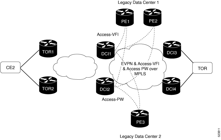
A CE device connects to multiple PE devices, with each CE-PE connection forming an individual Ethernet segment (ES). When these multiple Ethernet segments are combined and presented as a single logical segment to the CE device, this combined entity is called a virtual Ethernet segment (VES). The VES uses a PW as the logical link between the CE and PE devices to facilitate access to EVPN bridges. This architecture supports network resilience and efficient traffic distribution by enabling access through both pseudowires and AC sub-interfaces.


How virtual Ethernet segment works

Summary

The key components involved in the VES traffic flow process are:

  • CE2: Customer edge device that initiates traffic.

  • DCI1 and DCI2: EVPN data centers connected to legacy data centers via access pseudowires on a single Ethernet segment.

  • PE1, PE2, and PE3: Provider edge devices in legacy data centers receiving traffic from EVPN data centers.

  • Designated Forwarder (DF) and non-DF: Roles elected by DCI1 and DCI2 to manage traffic forwarding and standby paths.

The VES process enables resilient traffic forwarding by having CE2 send traffic through EVPN data centers, which elect a DF to manage active paths while the non-DF remains on standby, ensuring efficient and redundant connectivity to legacy data center PEs.

Workflow

These stages describe how virtual Ethernet segment works.

  1. CE2 sends traffic to either DCI1 or DCI2 through the EVPN network.
  2. DCI1 and DCI2 advertise Type 4 routes and discover each other.
  3. DCI1 and DCI2 perform a DF election; one becomes the DF, and the other becomes the non-DF.
  4. For traffic destined to PE3 (Legacy Data Center 2), the DF forwards traffic through the access pseudowire on the single Ethernet segment; the non-DF path remains in standby.
  5. For traffic destined to PE1 and PE2 (Legacy Data Center 1), the DF forwards traffic to PE1 and PE2; the non-DF path remains in standby.

Result

This process ensures loop-free and resilient traffic forwarding between EVPN data centers and legacy data centers over a virtual Ethernet segment by using Type 4 route advertisement and designated forwarder election, optimizing traffic flow and providing redundancy.


Configure virtual Ethernet segment

Configure access PWs to act as VES, enabling resilient and loop-free forwarding between EVPN data centers and legacy data centers.

Use this task to set up VES on DCI1, DCI2, and PE3 devices, connecting EVPN data centers to legacy data centers through access pseudowires on a single Ethernet segment.

Procedure

1.

Configure DCI1 with bridge domain and assign EVI to the bridge domain.

Example:

Router# configure 
Router(config)# l2vpn 
Router(config-l2vpn)# bridge group bg1
Router(config-l2vpn-bg)# bridge-domain bd1
Router(config-bg-bd)# neighbor 70.70.70.70 pw-id 17300001
Router(config-bg-bd-pw)# evi 1 
Router(config-bg-bd-pw-evi)# member vni 10001
Router(config-bg-bd-pw-evi)# commit
Router# configure 
Router(config)# evpn 
Router(config-evpn)# virtual neighbor 70.70.70.70 pw-id 17300001
Router(config-evpn-ac-pw)# ethernet-segment
Router(config-evpn-ac-pw-es)# identifier type 0 12.12.00.00.00.01.00.00.03
Router(config-evpn-ac-pw-es)# bgp route-target 1212.8888.0003
Router(config-evpn-ac-pw-es)# exit
Router(config-evpn-ac-pw)# timers peering 15
Router(config-evpn-ac-pw-timers)# commit
2.

Configure DCI2 with bridge domain and assign EVI to the bridge domain.

Example:

Router# configure 
Router(config)# l2vpn 
Router(config-l2vpn)# bridge group bg1
Router(config-l2vpn-bg)# bridge-domain bd1
Router(config-bg-bd)# neighbor 70.70.70.70 pw-id 17300001
Router(config-bg-bd-pw)# evi 1 
Router(config-bg-bd-pw-evi)# member vni 10001
Router(config-bg-bd-pw-evi)# commit
Router# configure 
Router(config)# evpn 
Router(config-evpn)# virtual neighbor 70.70.70.70 pw-id 27300001
Router(config-evpn-ac-pw)# ethernet-segment
Router(config-evpn-ac-pw-es)# identifier type 0 12.12.00.00.00.01.00.00.03
Router(config-evpn-ac-pw-es)# bgp route-target 1212.8888.0003
Router(config-evpn-ac-pw-es)# exit
Router(config-evpn-ac-pw)# timers peering 15
Router(config-evpn-ac-pw-timers)# commit
3.

Configure EVPN with virtual ethernet segment on both DCI1 and DCI2.

Example:

Router(config)# evpn 
Router(config-evpn)# virtual neighbor 70.70.70.70 pw-id 27300001
Router(config-evpn-ac-pw)# ethernet-segment
Router(config-evpn-ac-pw-es)# identifier type 0 12.12.00.00.00.01.00.00.03
Router(config-evpn-ac-pw-es)# bgp route-target 1212.8888.0003
Router(config-evpn-ac-pw-es)# exit
Router(config-evpn-ac-pw)# timers peering 15
Router(config-evpn-ac-pw-timers)# commit
4.

Configure PE3 with bridge domain and assign the virtual ethernet segments of DC1 and DCI2 as neighbors to the bridge domain.

Example:

Router# configure 
Router(config)# l2vpn 
Router(config-l2vpn)# bridge group 73
Router(config-l2vpn-bg)# bridge-domain 73-1
Router(config-bg-bd)# neighbor 10.10.10.10 pw-id 17300001
Router(config-bg-bd-pw)# exit
Router(config-bg-bd)# neighbor 20.20.20.20 pw-id 27300001
Router(config-bg-bd)# commit
5.

Running configuration of virtual Ethernet segment.

Example:

/* On DCI1 */

l2vpn
 bridge group bg1
  bridge-domain bd1
   neighbor 70.70.70.70 pw-id 17300001
    evi 1
     member vni 10001
!

evpn
  virtual neighbor 70.70.70.70 pw-id 17300001
   ethernet-segment
    identifier type 0 12.12.00.00.00.01.00.00.03
    bgp route-target 1212.8888.0003
    !
  timers peering 15
!

/* On DCI2 */

l2vpn
 bridge group bg1
  bridge-domain bd1
   neighbor 70.70.70.70 pw-id 27300001
    evi 1
     member vni 10001
!

evpn
  virtual neighbor 70.70.70.70 pw-id 27300001
   ethernet-segment
    identifier type 0 12.12.00.00.00.01.00.00.03
    bgp route-target 1212.8888.0003
    !
  timers peering 15
!

/* On PE3 */
!
l2vpn
 bridge group bg73
  bridge-domain bd73-1
   neighbor 10.10.10.10 pw-id 17300001
   !
   neighbor 20.20.20.20 pw-id 27300001
				
!
6.

Use the show evpn ethernet-segment command to to verify the Ethernet segment ID and interface status.

Example:

Router# show evpn ethernet-segment 
Thu Mar  7 10:56:37.662 UTC

Ethernet Segment Id      Interface                          Nexthops            
------------------------ ---------------------------------- --------------------
0012.1200.0000.0100.0003 PW:70.70.70.70,17300001            N/A                           
RP/0/RP0/CPU0:ios#show evpn ethernet-segment  detail
Thu Mar  7 10:56:53.806 UTC
Legend:
  B   - No Forwarders EVPN-enabled,
  C   - MAC missing (Backbone S-MAC PBB-EVPN / Grouping ES-MAC vES),
  RT  - ES-Import Route Target missing,
  E   - ESI missing,
  H   - Interface handle missing,
  I   - Name (Interface or Virtual Access) missing,
  M   - Interface in Down state,
  O   - BGP End of Download missing,
  P   - Interface already Access Protected,
  Pf  - Interface forced single-homed,
  R   - BGP RID not received,
  S   - Interface in redundancy standby state,
  X   - ESI-extracted MAC Conflict
  SHG - No local split-horizon-group label allocated
  Hp  - Interface blocked on peering complete during HA event
  Rc  - Recovery timer running during peering sequence

Ethernet Segment Id      Interface                          Nexthops            
------------------------ ---------------------------------- --------------------
0012.1200.0000.0100.0003 PW:70.70.70.70,17300001            N/A                           
  ES to BGP Gates   : R
  ES to L2FIB Gates : Ready
  Virtual Access    :
     Name           : PW_70.70.70.70_17300001
     State          : Peering
     Num PW Up      : 0
  ESI ID            : 1
  ESI type          : 0
     Value          : 0012.1200.0000.0100.0003
  ES Import RT      : 1212.8888.0003 (Local)
  Source MAC        : 0000.0000.0000 (N/A)
  Topology          :
     Operational    : SH
     Configured     : Single-active (AApS) (default)
  

This configuration ensures resilient and loop-free forwarding over the virtual Ethernet segment by establishing access pseudowires on DCI1 and DCI2 and connecting them as neighbors to PE3’s bridge domain.