Introduces Layer 3 EVPN IGMP and MLD state synchronization, which synchronizes IPv4 IGMP and IPv6 MLD states across multiple PE devices, ensures reliable multicast delivery for FTTH networks, and simplifies configuration by eliminating complex L2 and IRB requirements using L3 subinterfaces.
Layer 3 EVPN IGMP and Multicast Listener Discovery (MLD) state synchronization is a network solution that
synchronizes IPv4 IGMP and IPv6 MLD states across multiple PE devices
ensures reliable and seamless multicast service delivery in residential fiber-to-the-home (FTTH) deployments, and
removes the need for complex L2 and integrated routing and bridging (IRB) configurations by utilizing L3 subinterfaces.
Table 1. Feature History Table
Feature Name
Release Information
Feature Description
Layer 3 EVPN IGMP and MLD state synchronization
Release 26.2.1
Introduced in this release on: Fixed Systems (8010 [ASIC: A100])
This feature is supported on:
8011-32Y8L2H2FH
8011-12G12X4Y-A/D
Layer 3 EVPN IGMP and MLD state synchronization
Release 25.4.1
Introduced in this release on: Fixed Systems (8700 [ASIC: K100])(select variants only*)
*This feature is supported on Cisco 8711-48Z-M routers.
Layer 3 EVPN IGMP and MLD state synchronization
Release 25.3.1
Introduced in this release on: Fixed Systems(8200, 8700, 8011)(select variants only*); Modular Systems (8800 [LC ASIC: P100])
You can ensure seamless and reliable multicast delivery in residential FTTH networks with IGMP and MLD state synchronization for L3 using EVPN. This feature synchronizes IPv4 IGMP and IPv6 Multicast Listener Discovery (MLD) states across multiple PE devices using L3 sub-interfaces, eliminating the need for complex L2 or IRB configurations. It supports both VRF and global routing table deployments, providing flexibility for various network designs.
*This feature is supported on:
8212-48FH-M
8711-32FH-M
8712-MOD-M
8011-4G24Y4H-I
Simplified multicast delivery in residential FTTH networks
In many fiber-to-the-home (FTTH) deployments, multicast receivers are located within residential networks where hosts do not communicate with each other. To minimize costs, service providers often deploy basic Layer 2 switches in these networks and connect them to Provider Edge (PE) devices using Layer 2 port channels. However, when PE devices terminate traffic at Layer 2, Integrated Routing and Bridging (IRB) interfaces must be configured to bridge Layer 2 and Layer 3 domains. This adds unnecessary complexity because there is no host-to-host communication in these environments.
Including L2 switching and IRB interfaces in such scenarios increases operational overhead without providing tangible benefits. A simpler architecture can be achieved by terminating access connections as Layer 3 subinterfaces on the PE device. This eliminates the need for IRB interfaces, streamlines forwarding logic, and results in a more efficient and cost-effective design for residential multicast delivery.
Using EVPN for IGMP and MLD state synchronization at Layer 3 ensures consistent IPv4 and IPv6 multicast group membership across multiple PE devices. This approach supports resilient multicast services in residential FTTH networks by leveraging Layer 3 connectivity. The design aligns with RFC 9251, providing robust and scalable multihoming capabilities.
Multihomed topologies for IGMP and MLD state synchronization
A multihomed topology for IGMP and MLD state synchronization is a network design that
connects CE devices to multiple PE devices
uses L3 subinterfaces for direct connections, and
supports multicast state synchronization to ensure uninterrupted service for both IPv4 and IPv6 multicast traffic.
Benefits of Layer 3 EVPN IGMP and MLD state synchronization
Layer 3 EVPN IGMP and MLD state synchronization offers several key benefits:
Simplifies network architecture by removing unnecessary Layer 2 switching in residential deployments.
Enhances scalability and lowers operational overhead through the adoption of L3 multihoming, as specified in RFC 9251.
Boosts multicast performance and reliability by streamlining forwarding processes, improving efficiency across different IP versions.
Guidelines for Layer 3 EVPN IGMP and MLD state synchronization
Do not change the standard multicast routing configuration when enabling Layer 3 EVPN IGMP and MLD state synchronization.
Use only bundle subinterfaces to support Layer 3 EVPN IGMP and MLD state synchronization.
Deploy this feature in both VRF and global routing table environments.
Configure all IGMP (IPv4) and MLD (IPv6) parameters—such as timers, versions, and querier settings—identically across all redundancy groups.
If static joins are necessary on multihomed ports, configure them identically across redundancy groups because static joins are not synchronized automatically.
When using PIM or PIMv6 with IGMP or MLD state synchronization, configure multicast redundancy in all-active mode only; single-active and port-active modes are not supported.
How Layer 3 EVPN IGMP and MLD state synchronization works
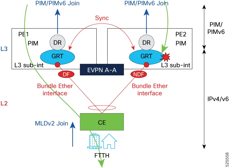
In EVPN multihoming, the designated forwarder (DF) exclusively forwards multicast traffic, including IGMP and MLD queries, to the customer edge, while the non-designated forwarder (NDF) blocks duplicates to prevent loops. This IGMP and MLD state synchronization ensures efficient, loop-free multicast delivery by coordinating forwarding roles across Layer 2 and Layer 3 components.
Summary
The key components involved in IGMP and MLD state synchronization are:
L3
PE1 and PE2: Both act as PE routers running PIM/PIMv6 (Protocol Independent Multicast for IPv4/IPv6) and connect to the customer edge (CE) via Bundle Ethernet interfaces.
Global routing table (GRT): Handles unicast and multicast routing.
Designated router (DR): Manages multicast group membership.
Designated forwarder (DF): Forwards multicast traffic on the shared segment as elected per EVPN rules.
In EVPN multihoming scenarios, the DF is responsible for forwarding multicast traffic, including IGMP and MLD queries, to the CE. Only the DF PE forwards such traffic, while the Non-Designated Forwarder (NDF) blocks it to prevent duplication and loops. This mechanism ensures that the CE receives a single, loop-free copy of multicast queries and traffic.
EVPN A-A (All-active): Enables both PEs to be active and participate in forwarding.
L2
CE: Device that receives L2 multicast (IGMP/MLD) joins from FTTH subscribers.
IGMP and MLD state synchronization ensures efficient and loop-free multicast delivery in EVPN active-active multihoming environments by coordinating state and forwarding roles among L2 and L3 network components.
Workflow
Figure 1. A sample toplogy for L3 EVPN IGMP and MLD state synchronization
This diagram illustrates the operation of L3 EVPN for synchronizing IGMP and MLD state across PE devices in a dual-homed all-active topology. The goal is to ensure consistent multicast group state between PE1 and PE2 for seamless multicast forwarding, even in the event of a link or device failure.
This example focuses on multicast running in the global routing table (GRT), but the process is the same when multicast operates in a VRF (MVPN).
These stages describe multicast state synchronization:
Reception of IGMP/MLD joins from the customer edge (CE): The CE device sends IGMP (for IPv4) or MLD (for IPv6) membership reports upstream to either PE1 or PE2 over the Layer 2 Bundle Ethernet interface to indicate interest in specific multicast groups.
State learning and actions: The PE that receives the IGMP or MLD join sends a PIM or PIMv6 join message to the core to request the multicast stream. Because both PEs act as PIM or PIMv6 DRs for the Bundle-Ether interface, either PE that receives the IGMP or MLD join will trigger a PIM or PIMv6 join to the core.
State synchronization between PEs: IGMP and MLD state information is synchronized between PE1 and PE2 using EVPN mechanisms. The PEs exchange synchronization messages containing IGMP and MLD states, including group membershipand source details, over the EVPN all-active control plane. This ensures both PEs maintain an identical view of multicast group membership, regardless of which PE received the original join.
Live-live redundancy: IGMP/MLD state synchronization allows the second PE to also send PIM or PIMv6 join towards the core to request the multicast stream. Both PEs receive the multicast stream from the core, ensuring live-live redundancy.
Multicast traffic forwarding: Both PEs receive the multicast traffic, but only the DF sends it through the Bundle-Ether interface. The non-designated forwarder (NDF) does not forward the traffic.
Failure scenario: If the Bundle-Ether interface on the DF fails, the second PE automatically becomes the DF and immediately forwards the multicast stream. This ensures uninterrupted multicast delivery.
Example scenario
A subscriber sends an IGMP join message for a TV multicast group from behind the CE device.
The CE forwards the IGMP join on one of the two bundle links; for example, the join is received by PE1.
Both PE1 and PE2 are designated routers (DRs). Regardless of which PE receives the IGMP join, a Protocol Independent Multicast (PIM) join is sent upstream to request multicast traffic.
PE1 exchanges its IGMP state with PE2 over EVPN active-active synchronization.
When PE2 receives the IGMP state over EVPN A-A, it also sends a PIM join upstream.
PE1 forwards the multicast stream through the Bundle-Ether interface because it is the DF.
If PE1 fails, PE2 already maintains the multicast group state and receives the stream from the core, allowing it to immediately take over forwarding multicast traffic to the subscriber.
Note
Because of IGMP/MLD state synchronization, the process operates the same way if the join is received on PE2, the non-designated forwarder, in step 2.
Configure Layer 3 EVPN IGMP and MLD state synchronization
Enable and maintain synchronized IGMP and MLD multicast group state across dual-homed PE routers in an EVPN all-active multihoming environment to ensure efficient, loop-free multicast delivery.
This task applies to Layer 3 EVPN deployments where PE routers connect to customer edge devices via Bundle Ethernet interfaces, supporting multicast traffic with redundancy and active-active forwarding.
Before you begin
Enable and activate the l2vpn evpn address family on peering with route reflectors to allow EVPN control plane messages to be exchanged between PEs.
Ensure that the same ESI value is configured under the EVPN settings on both PEs for the Bundle-Ether interface.
Layer 3 EVPN IGMP and MLD state synchronization requires the standard multicast configuration. For more details, see the Multicast Configuration Guide for Cisco 8000 Series Routers.
Procedure
1.
Configure the Ethernet Virtual Instance (EVI) to be used for EVPN synchronization.
Run the evpn route-sync <evi> command if multicast operates in GRT.
The evpn route-sync <evi> command enables route synchronization for a specific EVI in the GRT. Use this command when multicast operates in the GRT and the ESI and associated bundle subinterfaces are not tied to any VRF. The command ensures that Layer 3 routes for the EVPN instance are synchronized across all PE devices within the GRT.
Run the evpn route-sync <evi> command if multicast operates in default VRF.
The evpn route-sync <evi> command enables route synchronization for a specific EVI in the default VRF context. This command synchronizes Layer 3 routes learned on bundle subinterfaces or Ethernet segments for that EVPN instance across all PE devices within the default VRF.
Note
The ethernet-segment identifier type must match the one configured on the remote dual-homed PE router.
Run the vrf <name> evpn-route-sync <evi> command if multicast operates in a private VRF.
The vrf <name> evpn-route-sync <evi> command enables route synchronization for a specific EVI within a non-default VRF context. Use this command when the Ethernet segment identifier (ESI) and related bundle subinterfaces are part of a non-default VRF. The command ensures that Layer 3 routes for that EVPN instance are synchronized across all PE devices in the specified VRF.
Use a unique EVI number for this CLI; do not use the same EVI under l2vpn configuration for standard EVPN services.
2.
Use the show mfib platform evpn bucket loc <location> command to display EVPN bucket information for the specified location.
Example:
Router#show mfib platform evpn bucket loc 0/0/CPU0

-------------------------------------------------------------------------------
ESI Interface        Handle     Bucket ID  State  Ref cnt    Stale  Del pending
-------------------------------------------------------------------------------
BE1                  0x7800008c 8          NDF    0          F      F
BE1                  0x7800008c 9          DF     0          F      F
BE1                  0x7800008c 10         NDF    0          F      F
BE1                  0x7800008c 11         DF     0          F      F
BE1                  0x7800008c 4          NDF    0          F      F
BE1                  0x7800008c 5          DF     4          F      F
BE1                  0x7800008c 6          NDF    0          F      F
BE1                  0x7800008c 7          DF     0          F      F
BE1                  0x7800008c 0          NDF    0          F      F
BE1                  0x7800008c 1          DF     0          F      F
BE1                  0x7800008c 2          NDF    0          F      F
BE1                  0x7800008c 3          DF     0          F      F
BE2                  0x78000094 4          NDF    0          F      F
BE2                  0x78000094 5          DF     0          F      F
BE2                  0x78000094 6          NDF    0          F      F
BE2                  0x78000094 7          DF     0          F      F
BE2                  0x78000094 0          NDF    0          F      F
BE2                  0x78000094 1          DF     0          F      F
BE2                  0x78000094 2          NDF    0          F      F
BE2                  0x78000094 3          DF     0          F      F
BE2                  0x78000094 8          NDF    0          F      F
BE2                  0x78000094 9          DF     0          F      F
BE2                  0x78000094 10         NDF    0          F      F
BE2                  0x78000094 11         DF     0          F      F
-------------------------------------------------------------------------------
Router#
This output shows that EVPN multihoming is enabled with multiple buckets per ESI, and DF roles are distributed across different buckets and interfaces. The mix of DF and NDF states indicates active load balancing and redundancy, ensuring resiliency in multicast forwarding. No entries are stale or pending deletion.
3.
Use the show mrib platform idb command to display the multicast routing interface database (IDB) information for all interfaces on the platform.
This output shows that sub-interfaces Bundle-Ether1.10, Bundle-Ether1.11, and Bundle-Ether2.10 are registered for EVPN multihoming, each associated with their root bundle and ESI. The MH count indicates that each sub-interface is participating in a multihoming group with two members, confirming redundancy and active EVPN multihoming configuration.
4.
Use the show mfib vrf <vrf-name> platform route olist det location <location> command to display multicast forwarding details, highlighting EVPN multihoming information for each outgoing interface.
Example:
Use the show mfib vrf vpn101 platform route olist det location 0/0/CPU0 command to verify that both BE1.10 and BE1.11 subinterfaces are multihomed under the same ESI, with both acting as designated forwarders for multicast traffic.
Example:
Router#show mfib vrf vpn101 platform route olist det location 0/0/CPU0

------------------------------------------------------------------------------
Legend:
Route Information
    MC GID:    Multicast Index     NPI:     NP Independent

Outgoing Interface Information
    UL_Intf: Underlying Interface  UL_IFH:  Underlying Interface Handle
    L:       Local Interface       B:       Bundle Interface
    O:       In NPI Layer          OT:      OLE TYPE
    MRID:    Multicast Group Index DF:      Designated Forwarder
    EI:      ESI IFH               BI:      Bucket ID
    SE:      Last sync error reported in OFA
    AE:      Last async error reported in OFA
------------------------------------------------------------------------------


 VRF_ID: 0x0          Source: 40.10.1.2       Group: 232.0.0.1       Mask: 64

    SW Route Information
    ----------------------------
    Global MC GID: 317        Scale mode: Not-Set          Total OLE_CNT:2
    ------------------------------------------------------------------------------

    SW OLE Information
    ------------------------------------------------------------------------------
    Interface        IFH        UL_Intf     UL_IFH     L  B  O  SE   AE    NP
    ------------------------------------------------------------------------------
    BE1.11           0x780000a4 Hu0/0/0/0/1 0x368      F  T  T  0x0  0x0   0xff
    BE1.10           0x7800009c Hu0/0/0/0/1 0x368      F  T  T  0x0  0x0   0xff
    ------------------------------------------------------------------------------

    EVPN Multihoming Information
    -------------------------------------
    Intf            EI         BI  DF
    -------------------------------------
    BE1.11          0x7800008c 5   DF
    BE1.10          0x7800008c 5   DF
    -------------------------------------

    HW OLE NPI Information
    ------------------------------------------------------------------------------
    Interface   IFH        UL_Intf     UL_IFH     NP ID  MRID   OT       IC
    ------------------------------------------------------------------------------
    BE1.11      0x780000a4 Hu0/0/0/0/1 0x368      0x0    0      BE-Sub   F
    BE1.10      0x7800009c Hu0/0/0/0/1 0x368      0x0    0      BE-Sub   F
    ------------------------------------------------------------------------------

 VRF_ID: 0x0          Source: 40.10.1.2       Group: 232.0.0.2       Mask: 64

    SW Route Information
    ----------------------------
    Global MC GID: 318        Scale mode: Not-Set          Total OLE_CNT:2
    ------------------------------------------------------------------------------

    SW OLE Information
    ------------------------------------------------------------------------------
    Interface        IFH        UL_Intf     UL_IFH     L  B  O  SE   AE    NP
    ------------------------------------------------------------------------------
    BE1.11           0x780000a4 Hu0/0/0/0/0 0x2b0      F  T  T  0x0  0x0   0xff
    BE1.10           0x7800009c Hu0/0/0/0/0 0x2b0      F  T  T  0x0  0x0   0xff
    ------------------------------------------------------------------------------

    EVPN Multihoming Information
    -------------------------------------
    Intf            EI         BI  DF
    -------------------------------------
    BE1.11          0x7800008c 5   DF
    BE1.10          0x7800008c 5   DF
    -------------------------------------

    HW OLE NPI Information
    ------------------------------------------------------------------------------
    Interface   IFH        UL_Intf     UL_IFH     NP ID  MRID   OT       IC
    ------------------------------------------------------------------------------
    BE1.11      0x780000a4 Hu0/0/0/0/0 0x2b0      0x0    0      BE-Sub   F
    BE1.10      0x7800009c Hu0/0/0/0/0 0x2b0      0x0    0      BE-Sub   F
    ------------------------------------------------------------------------------
The output confirms that both BE1.10 and BE1.11 subinterfaces are multihomed under the same ESI, with both acting as designated forwarders for multicast traffic. This indicates a redundant and active-active multihoming setup, providing resiliency for multicast forwarding in the EVPN environment.
Use the show mfib vrf vpn101 platform route olist det location 0/RP0/CPU0 command to verify that the redundant EVPN multihoming setup is configured correctly, with multiple subinterfaces grouped into different ESIs.
Example:
Router# show mfib vrf vpn101 platform route olist det location 0/RP0/CPU0

------------------------------------------------------------------------------
Legend:
Route Information
    MC GID:    Multicast Index     NPI:     NP Independent

Outgoing Interface Information
    UL_Intf: Underlying Interface  UL_IFH:  Underlying Interface Handle
    L:       Local Interface       B:       Bundle Interface
    O:       In NPI Layer          OT:      OLE TYPE
    MRID:    Multicast Group Index DF:      Designated Forwarder
    EI:      ESI IFH               BI:      Bucket ID
    SE:      Last sync error reported in OFA
    AE:      Last async error reported in OFA
------------------------------------------------------------------------------


 VRF_ID: 0x0          Source: 40.10.1.2       Group: 232.0.0.1       Mask: 64

    SW Route Information
    ----------------------------
    Global MC GID: 318        Scale mode: Not-Set          Total OLE_CNT:3
    ------------------------------------------------------------------------------

    SW OLE Information
    ------------------------------------------------------------------------------
    Interface        IFH        UL_Intf     UL_IFH     L  B  O  SE   AE    NP
    ------------------------------------------------------------------------------
    BE1.11           0x780000a4 FH0/0/0/1   0x78000198 F  T  T  0x0  0x0   0xff
    BE1.10           0x7800009c FH0/0/0/1   0x78000198 F  T  T  0x0  0x0   0xff
    BE2.10           0x780000d4 FH0/0/0/2   0x780001a0 F  T  T  0x0  0x0   0xff
    ------------------------------------------------------------------------------

    EVPN Multihoming Information
    -------------------------------------
    Intf            EI         BI  DF
    -------------------------------------
    BE1.11          0x7800008c 5   NDF
    BE1.10          0x7800008c 5   NDF
    BE2.10          0x78000094 5   NDF
    -------------------------------------

    HW OLE NPI Information
    ------------------------------------------------------------------------------
    Interface   IFH        UL_Intf     UL_IFH     NP ID  MRID   OT       IC
    ------------------------------------------------------------------------------
    BE1.11      0x780000a4 FH0/0/0/1   0x78000198 0x0    0      BE-Sub   F
    BE1.10      0x7800009c FH0/0/0/1   0x78000198 0x0    0      BE-Sub   F
    BE2.10      0x780000d4 FH0/0/0/2   0x780001a0 0x0    0      BE-Sub   F
    ------------------------------------------------------------------------------

 VRF_ID: 0x0          Source: 40.10.1.2       Group: 232.0.0.2       Mask: 64

    SW Route Information
    ----------------------------
    Global MC GID: 319        Scale mode: Not-Set          Total OLE_CNT:3
    ------------------------------------------------------------------------------

    SW OLE Information
    ------------------------------------------------------------------------------
    Interface        IFH        UL_Intf     UL_IFH     L  B  O  SE   AE    NP
    ------------------------------------------------------------------------------
    BE1.11           0x780000a4 FH0/0/0/0   0x78000190 F  T  T  0x0  0x0   0xff
    BE1.10           0x7800009c FH0/0/0/0   0x78000190 F  T  T  0x0  0x0   0xff
    BE2.10           0x780000d4 FH0/0/0/2   0x780001a0 F  T  T  0x0  0x0   0xff
    ------------------------------------------------------------------------------

    EVPN Multihoming Information
    -------------------------------------
    Intf            EI         BI  DF
    -------------------------------------
    BE1.11          0x7800008c 5   NDF
    BE1.10          0x7800008c 5   NDF
    BE2.10          0x78000094 5   NDF
    -------------------------------------

    HW OLE NPI Information
    ------------------------------------------------------------------------------
    Interface   IFH        UL_Intf     UL_IFH     NP ID  MRID   OT       IC
    ------------------------------------------------------------------------------
    BE1.11      0x780000a4 FH0/0/0/0   0x78000190 0x0    0      BE-Sub   F
    BE1.10      0x7800009c FH0/0/0/0   0x78000190 0x0    0      BE-Sub   F
    BE2.10      0x780000d4 FH0/0/0/2   0x780001a0 0x0    0      BE-Sub   F
    ------------------------------------------------------------------------------
This output shows a redundant EVPN multihoming setup with multiple subinterfaces grouped into different ESIs. However, for the listed multicast groups, none of these local interfaces are acting as the designated forwarder, indicating that the DF role is handled elsewhere or is pending election.