Cisco Catalyst 9800 Series Wireless Controller Software Configuration Guide, Cisco IOS XE 26.1.x

PDF

Cisco Catalyst 9800 Series Wireless Controller Software Configuration Guide, Cisco IOS XE 26.1.x

Local web authentication

Want to summarize with AI?

Log in

Introduces local web authentication concepts, detailing authentication process, device roles, usage restrictions, customizable web pages, banners, and guidelines. Guides configuration through GUI and CLI, including HTTP/HTTPS requests, parameter maps, WLANs, ACLs, banners, TrustPoint, and provides practical configuration examples.


Local web authentication is a network security mechanism that

  • authenticates users through a web browser login page

  • enables access control on host systems that do not run IEEE 802.1X supplicants, and

  • communicates with authentication, authorization, and accounting (AAA) servers to enforce security policies.

Feature history

Feature Name

Release

Description

Built-in Captive Portal Improvement

Cisco IOS XE 17.1.1

This release introduces support for special characters in the login portal banner title and banner text. The number of characters supported on the banner text has doubled to 400.

The exec-character-bits command has been introduced.

Presentation options for local web authentication web pages

Local web authentication intercepts HTTP sessions on Layer 2 interfaces, and in some cases, Layer 3 interfaces (with restrictions for some switch models). When users try to access the network, local web authentication displays a login page and verifies user credentials with AAA servers, granting or denying access accordingly.

Local web authentication is categorized by the location where its web pages are hosted.

  • Internal: Uses HTML pages (login, success, fail, and expire) stored on the controller .

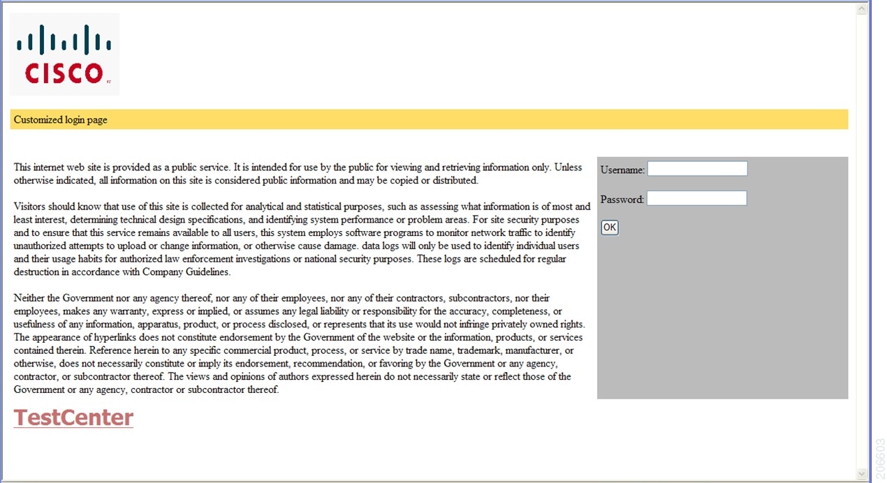
  • Customized: Uses customized HTML pages (login, success, fail, and expire) downloaded onto the controller for a customized user experience.

  • External: Uses HTML pages hosted on an external web server.

We recommend that you follow the Cisco guidelines to create a customized web authentication login page. If you use the latest versions of Google Chrome or Mozilla Firefox browsers, ensure that your webauth bundle uses this line in the login.html file:
<body onload="loadAction();">

Web authentication modes

The types of web authentication differ according to the available web authentication pages.

  • Webauth—The controller displays a page with the user name and password. Users enter valid credentials to gain network access.

  • Consent or web-passthrough—The controller presents a policy page with the Accept and Deny buttons. Users simply click Accept to access the network – no credentials are required.

  • Webconsent—This mode combines the features of Webauth and Consent. The controller displays a policy page with Accept or Deny buttons along with user name or password. Users must enter the correct credentials and click Accept to access the network.

Additional reference information

  • You can view the webauth parameter-map information using the show running-config command.

  • If you see tracebacks during client authentication, performance and behavior are not affected. Tracebacks may occur if Flexible Forwarding Mode (FFM) replies to Endpoint Profiler Module (EPM) for ACL application after the session is dequeued, usually because a timer expired or the session became unauthorized.

  • Apply web authentication methods (such as consent, web consent, and webauth) using either a global or named parameter-map under WLAN (for method-type, custom, and redirect). If you do not configure a parameter-map under WLAN, the global parameter-map applies by default.

  • You can configure web-based authentication on Layer 2 and layer 3 interfaces.

  • When a client reaches the maximum limit of 200 HTTP connections, the system resets TCP connections and excludes your client from the network.
How local web authentication works

Summary

authentication enables secure network access for clients by prompting users to authenticate through a web login page. The process coordinates actions between the user, authentication server, and the network switch. The key components are:

  • User: Initiates the HTTP session and enters authentication credentials.

  • Network switch: Intercepts traffic, presents login pages, applies policies, and communicates with the authentication server.

  • Authentication server: Verifies credentials and provides policy enforcement details.

Workflow

These are the stages of the process.

  1. Session initiation: The user starts an HTTP session by attempting to access the network.
  2. Traffic interception and login page presentation: The network switch intercepts the HTTP request and triggers the authorization process. It presents a login page for the user to enter their username and password.
  3. Credential submission and authentication: After the user submits credentials, the switch forwards them to the authentication server
  4. Authentication outcome:
    • If authentication succeeds, the switch downloads and activates the access policy assigned to the user from the server, then displays a login success page.
    • If authentication fails, the switch displays a login failure page. After a maximum number of failures, the login expired window appears, and the host is put on a watch list. Once the timeout expires, the user may try again
  5. Server non-response handling: If the authentication server does not respond, and an AAA fail policy is in place, the switch applies the failure policy to the host and displays a login success page.
  6. Reauthentication triggers: The switch reauthenticates a client if the host does not respond to an ARP probe (Layer 2) or does not send traffic within an idle timeout (Layer 3) suppress-feature-id="uabu_2960l_sw".
  7. Session timeout enforcement: The switch applies either the session timeout configured locally or provided by the server. The default local web authentication session timeout on controller is 1800 seconds from Cisco IOS XE 16.1.1 and later. The default session timeout value was infinite seconds, prior to Cisco IOS XE Denali 16.1.1.
  8. Session termination:
    • If the terminate action is set to RADIUS, the switch sends a nonresponsive host request to the server; the server’s response dictates the next action.
    • If the terminate action is set to default, the switch dismantles the session and removes the access policy.

Result

If authentication succeeds and the correct policies are applied, the user gains network access. If authentication fails, failure policies or timeout mechanisms may deny access.


Restrictions

  • You cannot configure bypass authentication with the wireless web authentication feature.

  • To update the redirect login URL, enable and then disable the WLAN. The redirect login URL specified in the web authentication parameter map changes when an AP rejoins.

  • If authentication fails, users receive a failure page and can try to log in again. If the number of allowed attempts is exceeded, users may be excluded and receive a specific reason for the exclusion.

  • Use the local web authentication feature to authenticate end users on host systems that do not run the IEEE 802.1x supplicant.


Roles of devices in local web authentication

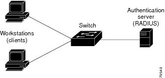
In a local web authentication scenario, network devices assume specific roles to manage authentication and access to the LAN.

  • Client: A device, such as a workstation, that requests network access and responds to authentication requests from the switch. The client must have an HTML browser with JavaScript enabled.

  • Authentication server: A server that validates the identity of the client. The authentication server notifies the switch if the client is allowed or denied access to the LAN and related services.

  • Switch: A network device that manages physical access to the network based on the authentication status of the client. The switch relays identity information and authorization responses between the client and the authentication server.

These device roles work together to ensure secure access control through local web authentication processes.

Figure 1. Local web authentication device roles

Local web authentication banners provide visual feedback to users during authentication on switches. The banners can display default or customized messages. They may also include branding or additional information on the login and result screens.

Default banner messages

When web authentication is enabled, one of these default messages appears on both the login screen and the authentication result pop-up page:

  • Authentication Successful

  • Authentication Failed

  • Authentication Expired

Commands to configure local web authentication banner

You can configure the local web authentication banner using the new style (Session-aware) CLI mode.

Use the command in the global configuration mode:

Device(config)# parameter map type webauth global
Device(config-params-parameter-map)# banner ?
file <file-name>
text <Banner text>
title <Banner title>

You can add a custom message, such as a switch, router, or company name, to the banner using the command:

Device(config)# parameter map type webauth global
Device(config-params-parameter-map)# banner text <text>

You can add a logo or text file to the banner using the command:

Device(config)# parameter map type webauth global
Device(config-params-parameter-map)# banner text <filepath>

Banner examples

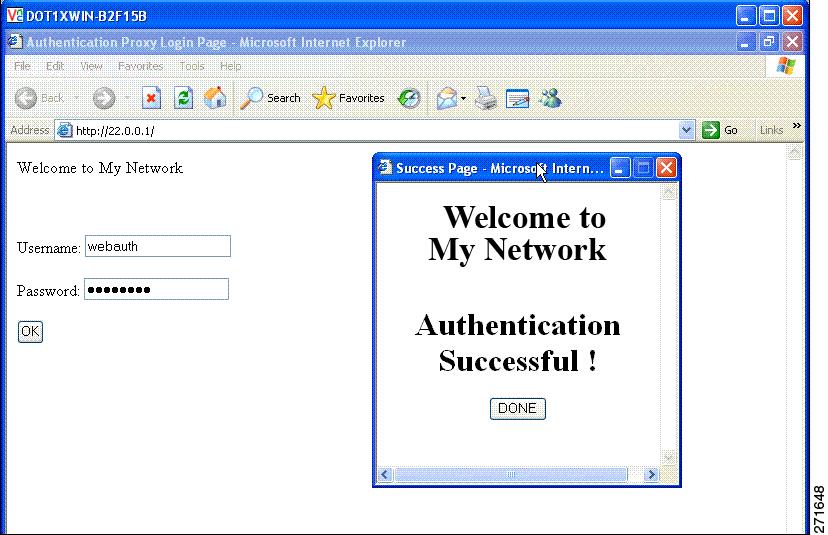
Figure 2. Customized web banner: Authentication Successful
Customized web banner with 'Authentication Successful
Figure 3. Login screen with no banner
Login screen showing no banner present.

Banner usage and behavior

  • The default banners are Cisco Systems and Switch host-name Authentication. These banners appear on the login page. The Cisco Systems banner also appears on the authentication result pop-up page.

  • The default banners appear unless custom banners are configured.

  • If you do not enable a banner, only username and password dialog boxes appear on the web authentication login screen. You will not see a banner when you log into the switch.


Authentication states in customized local web authentication

During local web authentication, the switch’s internal HTTP server hosts four HTML pages that communicate authentication states to the client.

You can replace the default internal HTML pages or specify a URL that redirects users after authentication. This URL replaces the internal Success page.

The four authentication pages and states are:

  • Login: Credentials are requested from the client.

  • Success: The client has authenticated successfully.

  • Fail: Authentication attempt failed.

  • Expire: The session expires after excessive failures.

You must configure all four pages. You can specify text or add a logo to each of the four pages.

Banner examples

Figure 4. Customizable Authentication Page
Customizable Web Authentication banner

Best practices for customizing web authentication pages

  • Add appropriate text to the banner and login pages as needed.

  • Always include a valid HTML redirect command in the success page to redirect users to a specific URL after login

  • Ensure the URL string is well-formed (for example, "http://www.cisco.com") to avoid browser errors.

  • If you configure web pages for HTTP authentication, include the appropriate HTML commands. For example, HTML commands to set the page time out, to set a hidden password, or to confirm that the same page is not submitted twice.

  • You can copy the configured web pages to the switch boot flash or the flash.

  • The login page can reside on one flash device, while the success and failure pages can be stored on another flash device

  • You must configure all four pages.

  • All logo files—including image, flash, audio, video, and similar file types—stored in the system directory must use web_auth_<filename> as the file name. System directory examples are flash, disk0, or disk.

  • You can copy the configured web pages to the switch boot flash or the flash.


Restrictions for customizing web authentication pages

  • The banner page has no effect if it is configured together with a web authentication page.

  • When the configured login form is enabled, the CLI command for redirecting users to a specific URL is unavailable. Configure redirection in the web page.

  • If you enter the CLI command to redirect users to a specific URL after authentication and then configure web pages, the redirect command does not take effect.

  • The configured authentication proxy feature supports both HTTP and SSL.


Guidelines for configuring a redirection URL for Successful Login page

  • If you enable the custom authentication proxy web pages feature, you cannot use the redirection URL feature in the CLI. To redirect users after login, configure redirection in the custom login success page.

  • If you enable the redirection URL feature, the configured authorization proxy banner is not be used.

  • To remove the specification of a redirection URL, use the no form of the command.

  • If a redirection URL is required after successful authentication, it must begin with a valid protocol prefix (such as http://) followed by the URL. If http:// is omitted, the browser might show a page not found error or similar issue


How to configure local web authentication


Configure default local web authentication

Table 1. Default local web authentication configuration

Feature

Default Setting

AAA

Disabled

RADIUS server

  • IP address

  • UDP authentication port

  • Key

  • None specified

Default value of inactivity timeout

3600 seconds

Inactivity timeout

Enabled


Configure AAA settings using the wizard

Use the AAA Wizard to streamline the addition of authentication, authorization, and accounting (AAA) servers and settings through a guided interface.

The AAA wizard helps you add the authentication, authorization and accounting details without going into multiple screens.

The AAA Wizard guides you through configuring RADIUS, TACACS+, and LDAP servers, and mapping AAA server groups and methods. If you need to edit details entered with the wizard, use the appropriate configuration screens.

Note

Configure attribute formats as listed in the Supported authentication and authorization attribute formats section to ensure successful transactions.

Before you begin

Ensure you have network information and credentials available for the AAA servers to be configured.

Procedure

1.

Choose Configuration > Security > AAA.

2.

Click + AAA Wizard.

The Add Wizard window is displayed.

3.

Go to the RADIUS tab.

The RADIUS server option is enabled by default. You can switch between Basic and Advanced options using the radio buttons.

  1. In the Name field, enter the name of the RADIUS server.

  2. In the IPv4 / IPv6 Server Address field, enter the IPv4 or IPv6 address, or hostname of the server.

  3. Select the PAC Key check box to enable Protected Access Credential (PAC) authentication key option.

  4. From the Key Type drop-down list, select the authentication key type.

  5. In the Key field, enter the authentication key.

  6. In the Confirm Key field, re-enter the authentication key.

  7. Click Advanced radio button.

    This enables the advanced options.

  8. In the Auth Port field, enter the authorization port number.

  9. In the Acct Port field, enter the accounting port number.

  10. In the Server Timeout field, enter the timeout duration, in seconds.

  11. In the Retry Count field, enter the number of retries.

  12. In the Support for CoA field, use the toggle button to enable or disable change-of-authorization (CoA).

4.

To enter TACACS+ options, check the TACACS+ check box.

This enables the TACACS+ options. You can switch between Basic and Advanced options using the radio buttons.

  1. In the Name field, enter the TACACS+ server name.

  2. In the IPv4 / IPv6 Server Address field, enter the IPv4 or IPv6 address, or hostname.

  3. In the Key field, enter the authentication key.

  4. In the Confirm Key field, re-enter the authentication key.

  5. Click Advanced radio button.

    This enables the advanced options.

  6. In the Port field, enter the port number to use.

  7. In the Server Timeout field, enter the timeout duration, in seconds.

5.

To enter LDAP options, check the LDAP check box.

This enables the LDAP options. You can switch between Basic and Advanced options using the radio buttons.

  1. In the Server Name field, enter the LDAP server name.

  2. In the IPv4 / IPv6 Server Address field, enter the IPv4 or IPv6 address, or hostname.

  3. In the Port Number field, enter the port number to use.

  4. From the Simple Bind drop-down list, select the authentication key type.

  5. In the User Base DN field, enter the user base distinguished name.

  6. Click Advanced radio button.

    This enables the advanced options.

  7. From the User Attribute drop-down list, select the user attribute.

  8. In the User Object Type field, enter the details and click the + icon.

    The objects you add appear in the list, and you can use the x mark beside each object to remove it.

  9. In the Server Timeout field, enter the timeout duration, in seconds.

  10. Check the Secure Mode check box to enable secure mode.

    Selecting the Secure Mode option enables the Trustpoint Name drop-down list.

  11. From the Trustpoint Name drop-down list, select the trustpoint.

  12. Click Next.

    This enables the Server Group Association screen and RADIUS tab is selected by default.

6.

Go to the RADIUS tab.

  1. In the Name field, enter the name of the RADIUS server group.

  2. From the MAC-Delimiter drop-down list, choose the delimiter to be used in the MAC addresses that are sent to the RADIUS servers.

  3. From the MAC Filtering drop-down list, choose a value based on which to filter MAC addresses.

  4. To configure dead time for the server group and direct AAA traffic to alternative groups of servers that have different operational characteristics, in the Dead-Time field, enter the amount of time, in minutes, after which a server is assumed to be dead.

  5. Choose the servers that you want to include in the server group from the Available Servers list and move them to the Assigned Servers list.

  6. Click Next.

    The TACACS+ window is displayed, if you have selected TACACS+ in Server configuration.

7.

Use the TACACS+ window to enter details.

  1. In the Name field, enter the name of the TACACS+ server group.

  2. Choose the servers that you want to include in the server group from the Available Servers list and move them to the Assigned Servers list.

  3. Click Next.

    The LDAP window is displayed, if you have selected LDAP in server configuration.

8.

Use the LDAP window to enter details.

  1. In the Name field, enter the name of the LDAP server group.

  2. Choose the servers that you want to include in the server group from the Available Servers list and move them to the Assigned Servers list.

9.

Click Next.

The MAP AAA window is displayed.

You can use the check boxes to enable the Authentication, Authorization, and Accounting tabs. You cannot deselect all three options. At least one option has to be selected.

10.

Use the Authentication tab to enter authentication details.

  1. In the Method List Name field, enter the name of the method list.

  2. From the Type drop-down list, choose the type of accounting you want to perform before allowing access to the network.

  3. From the Group Type drop-down list, choose if you want to assign a group of servers as your access server, or if you want to use a local server to authenticate access.

    If you choose local option, Fallback to local option is removed.

  4. Check the Fallback to local check box to configure a local server to act as a fallback method when servers in the group are unavailable.

  5. From the Available Server Groups list, choose the server groups you want to use to authenticate access to your network and click > icon to move them to the Assigned Server Groups list.

11.

Check the Authorization check box to configure authorization details.

  1. In the Method List Name field, enter the name of the method list.

  2. From the Type drop-down list, choose the type of authorization you want to perform before allowing access to the network.

  3. From the Group Type drop-down list, choose if you want to assign a group of servers as your access server, or if you want to use a local server to authorize access.

    If you choose local option, Fallback to local option is removed.

  4. Check the Fallback to local check box to configure a local server to act as a fallback method when servers in the group are unavailable.

  5. From the Available Server Groups list, choose the server groups you want to use to authorize access to your network and click > icon to move them to the Assigned Server Groups list.

12.

Check the Accounting check box to configure accounting details.

  1. In the Method List Name field, enter the name of the method list.

  2. From the Type drop-down list, choose the type of accounting you want to perform.

  3. From the Available Server Groups list, choose the server groups you want to use to authorize access to your network and click > icon to move them to the Assigned Server Groups list.

13.

Click Apply to Device.

The system saves your AAA configuration, associating servers and methods as specified. AAA features are ready for use.


Configure AAA authentication (GUI)

Set up AAA authentication to control network access using the GUI.

Use this task to define and assign authentication methods and server groups for device access.

Before you begin

Confirm that server groups are configured if you plan to use them.

Procedure

1.

Choose Configuration > Security > AAA.

2.

In the Authentication section, click Add.

3.

In the Quick Setup: AAA Authentication window that is displayed, enter a name for your method list.

4.

Choose the type of authentication you want to perform before allowing access to the network, in the Type drop-down list.

5.

In the Group Type drop-down list, select either a group of servers as your access server or a local server to authenticate access.

6.

To configure a local server to act as a fallback method when servers in the group are unavailable, check the Fallback to local check box.

7.

Choose the server groups you want to use to authenticate access to your network, from the Available Server Groups list and click > icon to move them to the Assigned Server Groups list.

8.

Click Save & Apply to Device.

The controller is now configured with AAA authentication, and users are authenticated using the chosen methods.


Configure AAA authentication (CLI)

Enable authentication, authorization, and accounting (AAA) on the device to manage login methods and network access.

AAA centralizes user authentication for device access and network services. Select a named method list or the default list, depending on your VTY line configuration.

If no method list is configured under VTY lines, add the default method list to the AAA configuration.”

line vty 0 4 
 authorization commands 15 abc
aaa authorization commands 15 abc group tacacs+ 
If a method-list is not configured under VTY lines, you must add the default method list to the AAA configuration:
line vty 0 4
 aaa authorization commands 15 default group tacacs+

Note

Use the default list for AAA authorization if you plan to use features such as dACL.

Before you begin

Ensure that the TACACS+ server address and group name are available.

Procedure

1.

Enable AAA functionality.

Example:

Device
(config)# aaa new-model
2.

Define the list of authentication methods at login using the aaa authentication login {default | named_authentication_list} group AAA_group_name command.

Example:


Device(config)# aaa authentication login default group AAA_group_name

named_authentication_list refers to any name that is not greater than 31 characters.

AAA_group_name refers to the server group name. Define the server_name at the beginning of the configuration.

3.

Create an authorization method list for web-based authorization using the aaa authorization network {default | named_authorization_list} group AAA_group_name command.

Example:


Device(config)# aaa authorization network default group group1
4.

Specify an AAA server.

Example:


Device(config)# tacacs server yourserver
5.

Configure the IP address for the TACACS server.

Example:


Device(config-server-tacacs)# address ipv4 10.0.1.12
6.

Specify a AAA server.

Example:


Device(config)# tacacs-server host 10.1.1.1


Configure the HTTP or HTTPS server (GUI)

Set up HTTP and HTTPS access to enable secure web-based management of the device.

HTTP provides basic web access; HTTPS secures connections with SSL encryption. You can configure access ports, authentication, trust points, and session policies to meet your security requirements.

Before you begin

Confirm necessary certificates are available if using HTTPS trust points.

Procedure

1.

Choose Administration > Management > HTTP/HTTPS/Netconf.

2.

In the HTTP/HTTPS Access Configuration section, enable HTTP Access and enter the port that will listen for HTTP requests. The default port is 80. Valid values are 80, and ports between 1025 and 65535.

3.

Enable HTTPS Access on the device and enter the designated port to listen for HTTPS requests. The default port is 1025. Valid values are 443 and ports between 1025 and 65535. Data exchanged over a secure HTTP connection is encrypted before transmission across the Internet. SSL encryption over HTTP enables secure configuration of the switch through a web browser.

4.

Choose the Personal Identity Verification as enabled or disabled.

5.

In the HTTP Trust Point Configuration section, enable Enable Trust Point to use Certificate Authority servers as trustpoints.

6.

From the Trust Points drop-down list, choose a trust point.

7.

In the Timeout Policy Configuration section, enter the HTTP timeout policy in seconds. Enter a value between one to 600 seconds.

8.

Enter the number of minutes of inactivity allowed before the session times out. Enter a value between 180 and 1200 seconds.

9.

Enter the server life time in seconds. Enter a value between one and 86400 seconds.

10.

Enter the maximum number of requests the device can accept. Valid values range from one and 86400 requests.

11.

Save the configuration.

The device is configured for HTTP or HTTPS access according to your specified settings.


Configure the HTTP server (CLI)

Enable HTTP or HTTPS server functionality on your device to support local web authentication.

Local web authentication requires the HTTP server to be enabled on the controller.

You can configure both HTTP and HTTPS servers to support device management and user authentication.

Both HTTP and HTTPS servers can be configured to support device management and user authentication.

Note that some browsers, such as the Apple psuedo-browser, do not open if you configure only the ip http secure-server command. You should also configure the ip http server command.

Procedure

1.

Enable the HTTP server. The local web authentication feature uses the HTTP server to communicate with the hosts for user authentication.

Example:


Device(config)# ip http server
2.

Enable HTTPS.

Example:


Device(config)# ip http secure-server

You can configure custom authentication proxy web pages or specify a redirection URL for successful login.

Note

To ensure secure authentication when you enter the ip http secure-server command, the login page is always in HTTPS (secure HTTP) even if the user sends an HTTP request.

3.

Return to privileged EXEC mode.

Example:


Device(config)# end

The controller is now configured with the HTTP or HTTPS or both. This enables local web authentication and secure browser access for users.


Allow special characters for serial port

Configure the serial port to support special characters for advanced device communication.

Use this procedure when the connected device or application must process special characters on the serial console port.

Procedure

1.

Enter global configuration mode.

Example:

Device# configure terminal
2.

Configure the primary terminal line number.

Example:

Device(config)# line console 0
3.

Configure the time to disconnect idle EXEC sessions using the exec-timeout mins sec command.

Example:

Device(config-line)# exec-timeout 12 0
4.

Configure login authentication checking using the login authentication word default command.

Example:

Device(config-line)# login authentication NO_LOGIN
You can configure an authentication list with a name or use the default authentication list
5.

Configure the character widths of EXEC command characters using the exec-character-bit { 7 | 8} command.

Example:

Device(config-line)# exec-character-bit 8
6.

Configure the stop bits for the console port using the stopbits { 1 | 1.5| 2} command.

Example:

Device(config-line)# stopbits 1
7.

Return to privileged EXEC mode.

Example:

Device(config-line)# end

The serial port is now configured to support special characters according to your settings.


Allow special characters for VTY port

Enable the use of special (non-standard) characters in the banner text for Virtual Teletype (VTY) ports, which enhances customization options and supports global character sets.

You can allow special (non-standard) characters in the banner text for Virtual Teletype (VTY) ports. This lets you customize banners and support global character sets.

You may want to allow special characters in the banner displayed on the VTY port—for example, to include accented letters, non-English text, or symbols for branding or user communication.

Before you begin

Ensure you have determined the desired banner text and any required special characters.

Procedure

1.

Enter global configuration mode.

Example:

Device# configure terminal
2.

Create a parameter map and enter parameter-map webauth configuration mode.

Example:

Device(config)# parameter-map type webauth global
3.

Create a custom banner using the banner text text command.

Example:

Device(config-params-parameter-map)# banner text #Hêllö#

You can create a custom banner (of up to 400 characters) by entering c <banner-text> c, where c is a delimiting character.

If the banner text exceeds 400 characters (400 characters is about 250 words), you see an error message and the configuration is rejected. The parser limits each line to 254 characters (about 150 words), including CLI keywords. If you need more than 254 characters, split the banner text into multiple lines.

The webauth login page displays only the default banner strings, if banner command is not configured.

4.

Return to privileged EXEC mode.

Example:

Device(config-params-parameter-map)# end

You can now use special characters in the VTY port banner. When users connect through VTY, they see your custom banner.


HTTP and HTTPS access modes for web authentication

The table describes the various CLI combinations.

You can control HTTP and HTTPS access separately for device management (admin) and web authentication by configuring web authentication using CLI command combinations. The main commands involved are:

  • ip http server : Enables HTTP access to the device for administration.

  • ip http secure-server : Enables HTTPS access to the device for administration and is required for HTTPS access to web authentication.

  • webauth-http-enable (under parameter-map type webauth global) : Allows HTTP access for web authentication without enabling HTTP access for administration. This command is not enabled by default.

  • secure-webauth-disable (under parameter-map type webauth global ): Disables HTTPS access for web authentication only. This command is not enabled by default.

CLI combinations

The table describes the possible CLI combinations.

Admin (Device Management)

Web Authentication

Required Configurations

HTTP Access

HTTPS Access

HTTP Access

HTTPS Access

Admin

Web Authentication

No

Yes

Yes

Yes

no ip http server
ip http secure-server
no ip http server
ip http secure-server
parameter-map type webauth global
   webauth-http-enable

No

Yes

No

Yes

no ip http server
ip http secure-server
no ip http server
ip http secure-server

No

Yes

Yes

No

no ip http server
ip http secure-server
no ip http server
ip http secure-server
parameter-map type webauth global
   webauth-http-enable
   secure-webauth-disable

No

Yes

No

No

no ip http server
ip http secure-server
no ip http server
ip http secure-server
parameter-map type webauth global
   secure-webauth-disable

No

No

No

Yes

no ip http server
no ip http secure-server

Not supported

No

No

Yes

No

no ip http server
no ip http secure-server
no ip http server
no ip http secure-server
parameter-map type webauth global
   webauth-http-enable

Yes

No

Yes

No

ip http server
no ip http secure-server
ip http server
no ip http secure-server

Yes

Yes

Yes

No

ip http server
ip http secure-server
ip http server
ip http secure-server
parameter-map type webauth global
   secure-webauth-disable
  • To enable HTTP access for web authentication without also enabling HTTP administrative access, configure webauth-http-enable in parameter-map type webauth global mode. Do not use ip http server .

  • HTTPS access for web authentication always requires ip http secure-server .

  • To disable HTTPS access for web authentication, use the secure-webauth-disable command.

  • These combinations allow granular control over how users can access the device for both management and web authentication purposes.


Limitations

These guidelines and limitations help you configure HTTP and HTTPS requests for web authentication.

  • Enable HTTPS for device management before you enable HTTPS web authentication

  • If secure-webauth-disable is configured and the client's initial request is https://< >, central web authentication cannot be performed.


Configure HTTP and HTTPS requests for web authentication (CLI)

Configure HTTP and HTTPS server parameters to support secure web authentication.

Perform this configuration when you need to enable or disable HTTP or HTTPS web authentication features on your device.

Procedure

1.

Enable privileged EXEC mode.

Example:

Device# enable

Enter your password if prompted.

2.

Enter global configuration mode.

Example:

Device# configure terminal
3.

Set the HTTP server to default.

Example:

Device(config)# no ip http server
4.

Enable the HTTP server or the HTTP secure server using the ip http {server | secure-server} command.

Example:

Device(config)# ip http server
5.

Enable the global parameter map mode.

Example:

Device(config)# parameter-map type webauth global
6.

Disable HTTP secure server for web authentication.

Example:

Device(config-params-parameter-map)# secure-webauth-disable
7.

Enable HTTP server for web authentication.

Example:

Device(config-params-parameter-map)# webauth-http-enable

The device is configured to send HTTP requests, HTTPS requests, or both to the web authentication module according to your settings.


Create Parameter Maps


Create a parameter map (GUI)

Define criteria-based policies to control device and user access within the local policy framework.

Use this task to create a parameter map by specifying match criteria and associating service templates. This enables dynamic policy application based on device type, user role, and other attributes.

Before you begin

Ensure you have the required policy details and service templates ready.

Procedure

1.

Choose Configuration > Security > Local Policy.

2.

Click Add.

3.

Click Policy Map.

4.

Enter Policy Map Name.

5.

In the Match Criteria List settings, click Add.

6.

In the Add Match Criteria settings, choose the service template from the Service Template drop-down list.

7.

Choose the filters from Device Type, User Role, User Name, OUI, and MAC Address drop-down lists.

8.

Click Add Criteria.

9.

Click Apply to Device.

The parameter map is created and applied, enabling policy enforcement based on the selected criteria.


Configure local web authentication (GUI)

Enable local web authentication for your network using GUI.

Use this task to set authentication parameters, banner messages, and related settings for web authentication.

Procedure

1.

Choose Configuration > Security > Web Auth.

2.

On the Web Auth page, click Add.

3.

In the Create Web Auth Parameter window that is displayed, enter a name for the parameter map.

4.

In the Maximum HTTP Connections field, enter the maximum number of HTTP connections that you want to allow.

5.

In the Init-State Timeout field, enter the timeout duration. The timer expires if the user does not enter valid credentials on the login page

6.

Choose the type of Web Auth parameter.

7.

Click Apply to Device.

8.

On the Web Auth page, click the name of the parameter map.

9.

In the Edit WebAuth Parameter window that is displayed, choose the required Banner Type.

  • If you choose Banner Text, enter the required banner text to be displayed.
  • If you choose File Name, specify the path of the file from which the banner text has to be picked up.
10.

Enter the virtual IP addresses as required.

11.

Set the status of WebAuth Intercept HTTPS, Captive Bypass Portal, and Watch List Enable as required.

12.

In the Watch List Expiry Timeout field, enter the time in seconds after which the watch list should time out.

13.

Set the status for Disable Success Window, Disable Logout Window, and Login Auth Bypass for FQDN, as required.

14.

Check the Sleeping Client Status check box to enable authentication of sleeping clients. Specify the Sleeping Client Timeout in minutes. The valid range is 10 to 43,200 minutes.

15.

Click the Advanced tab.

16.

In the Redirect for log-in field, enter the name of the external server to which to send the login request.

17.

In the Redirect On-Success field, enter the name of the external server to redirect after a successful login.

18.

In the Redirect On-Failure field, enter the name of the external server to redirect after a login failure.

19.

To configure external local web authentication, perform these steps:

  1. Under Redirect to External Server in the Redirect Append for AP MAC Address field, enter the AP MAC address.

  2. In the Redirect Append for Client MAC Address field, enter the client MAC address.

  3. In the Redirect Append for WLAN SSID field, enter the WLAN SSID.

  4. In the Portal IPV4 Address field, enter the IPv4 address of the portal to send redirects.

  5. In the Portal IPV6 Address field, enter the IPv6 address of the portal to send redirects if you are using an IPv6 address.

20.

To configure customized local web authentication, perform these steps:

  1. Under Customized Page, specify the following pages:

    • Login Failed Page

    • Login Page

    • Logout Page

    • Login Successful Page

21.

Click Update & Apply.

Local web authentication is enabled with your specified settings.


Configure internal local web authentication (CLI)

Set up internal local web authentication on your device using CLI.

Procedure

In the global configuration mode, create a parameter map

Example:


Device(config)# parameter-map type webauth sample

Creates the parameter map.

The name of the parameter map must not exceed 99 characters.

You have configured internal local web authentication.

The device prompts clients to authenticate through the web portal. After authentication, the device grants full network access.


Configure the customized local web authentication (CLI)

Configure custom local web authentication workflow on a Cisco device by specifying custom portal pages using CLI.

Perform this procedure to offer users a personalized login, success, and failure experience during web authentication.

Before you begin

  • Ensure you have valid HTML files for login, success, expired, and failure pages uploaded to device storage.

  • Configure a virtual IP in the global parameter map to use the customized web authentication bundle.

Procedure

1.

Configure the webauth type parameter.

Example:

Device(config)# parameter-map type webauth parameter-map-name
					

Configure a virtual IP in the global parameter map so the device uses the customized web authentication bundle.

2.

Configures webauth sub-types using the type {authbypass | consent | webauth | webconsent} command.

Example:

Device(config-params-parameter-map)# type webauth


The types are passthru, consent, webauth, or webconsent.

3.

Configure the customized login page using the custom-page login device html-filename command.

Example:

Device(config-params-parameter-map)# custom-page login device bootflash:login.html
4.

Configure the customized login expiry page using the custom-page login expired device html-filename command.

Example:

Device(config-params-parameter-map)# custom-page login expired device bootflash:loginexpired.html
5.

Configure the customized login success page using the custom-page success device html-filename command.

Example:

Device(config-params-parameter-map)# custom-page success device bootflash:loginsuccess.html
6.

Configure the customized login failure page using the custom-page failure device html-filename command.

Example:

Device(config-params-parameter-map)# custom-page failure device bootflash:loginfail.html

You have configured the customized local web authentication portal. Users can see the specified custom pages during authentication.


Configure the external local web authentication (CLI)

Enable external local web authentication on your device by configuring the required CLI parameters.

Use this procedure to set up external local web authentication settings, including parameter maps and redirect URLs, using the CLI.

Before you begin

Gather the parameter map name and redirect URLs.

Procedure

1.

Enter global configuration mode.

Example:


Device# configure terminal
2.

Configure the webauth type parameter.

Example:


Device(config)# parameter-map type webauth sample
3.

Configure web authentication subtypes by using the type {authbypass | consent | webauth | webconsent} command.

Example:


Device(config-params-parameter-map)# type webauth
4.

Configure the redirect URL for the login, failure, and success pages using the redirect [for-login | on-failure | on-success] URL command.

Example:


Device(config-params-parameter-map)# redirect for-login
http://www.cisco.com/login.html
Note

In the redirect URL, you need to press Ctrl+v and type ? to configure the ? character.

The ? character is commonly used in URL when ISE is configured as an external portal.

5.

Configure the external portal IPv4 address using the redirect portal {ipv4 | ipv6} ip-address command.

Example:


Device(config-params-parameter-map)# redirect portal ipv4 23.0.0.1

When using FQDN, use an IP address associated with the domain. If the domain resolves to more than one IP address, use the FQDN URL instead of an individual IP address.

6.

Return to privileged EXEC mode.

Example:


Device(config-params-parameter-map)# end

You have configured external local web authentication. Your device redirects users to the correct portal for authentication events, based on your parameter map and settings.


Configure the web authentication WLANs

Configure a WLAN with web authentication security using CLI. Map authentication lists and parameter maps using the CLI.

Perform this task to set up a WLAN that uses web authentication, specifying key identifiers and settings through the CLI on your network device.

Procedure

1.

Enter global configuration mode.

Example:


Device# configure terminal

2.

Enter the WLAN configuration sub-mode.

Example:


Device(config)# wlan wlan-name wlan-id SSID-name

3.

Disable WPA security.

Example:


Device(config-wlan)# no security wpa

4.

Enable web authentication for WLAN.

Example:


Device(config-wlan)# security web-auth
5.

Enable web authentication for WLAN using the security web-auth {authentication-list authentication-list-name | parameter-map parameter-map-name} command.

Example:


Device(config-wlan)# security web-auth authentication-list webauthlistlocal
Device(config-wlan)# security web-auth parameter-map sample

Here is a description of some of the parameters.

  • authentication-list authentication-list-name : Sets the authentication list for IEEE 802.1x.

  • parameter-map parameter-map-name : Configures the parameter map.

Note

When security web-auth is enabled, you can map the default authentication-list and global parameter-map . This is applicable for authentication-list and parameter-map that are not explicitly mentioned.

6.

Return to privileged EXEC mode.

Example:


Device(config-wlan)# end

The WLAN is configured with web authentication security and the desired authentication and parameter settings.


Configure pre-auth web authentication ACL (GUI)

Map a pre-authentication access control list (ACL) to a WLAN to control network access for users before authentication.

Use this procedure to enforce security policies by restricting network access to specified resources while users are in the pre-authenticated state on a wireless LAN.

Before you begin

Ensure that you have configured an ACL and a WLAN.

Procedure

1.

Choose Configuration > Tags & Profiles > WLANs.

2.

Click the name of the WLAN.

3.

In the Edit WLAN window, click the Security tab and then click the Layer3 tab.

4.

Click Show Advanced Settings.

5.

In the Preauthenticaion ACL section, choose the appropriate ACL to map to the WLAN.

6.

Click Update & Apply to Device.

When you connect to this WLAN, you must adhere to the access restrictions defined by the ACL until authentication is complete.


Configure pre-authentication web authentication ACL (CLI)

Set up a pre-authentication web authentication access control list (ACL) and apply it to a WLAN using CLI commands. This configuration ensures only authorized traffic passes through before web authentication occurs.

Use this task to control the network traffic permitted before clients authenticate on a WLAN. The ACL defines which clients and protocols are permitted through during the web authentication process.

Before you begin

  • Gather the required network and client information.

  • Determine the ACL rules (permit or deny) and relevant addresses.

Procedure

1.

Enters global configuration mode.

Example:


Device# configure terminal

2.

Create an ACL list using the access-list access-list-number {deny | permit} hostname source-wildcard-bits command.

Example:


Device(config)# access-list 2 deny your_host 10.1.1.1 log

The access-list-number is a decimal number from one to 99, 100 to 199, 300 to 399, 600 to 699, 1300 to 1999, 2000 to 2699, or 2700 to 2799.

Enter deny or permit to specify whether to deny or permit if the conditions are matched.

The source is the source address of the network or host from which the packet is being sent specified as:

  • The 32-bit quantity in dotted-decimal format.

  • The keyword any as an abbreviation for source and source-wildcard of 0.0.0.0 255.255.255.255. You do not need to enter a source-wildcard.

  • The keyword host as an abbreviation for source and source-wildcard of source 0.0.0.0.

(Optional) The source-wildcard applies wildcard bits to the source.

Note

The AP forwards traffic if it matches any of the ACLs applied in the pre-authentication ACLs. Use bidirectional rules for clients in web authentication pending state and for downstream traffic.

3.

Create the WLAN.

Example:


Device(config)# wlan mywlan 34 mywlan-ssid

profile-name is the WLAN name which can contain up to 32 alphanumeric characters.

wlan-id is the wireless LAN identifier. The valid range is from one to 512.

ssid-name is the SSID which can contain 32 alphanumeric characters.

4.

Map the ACL to the web auth WLAN.

Example:


Device(config-wlan)# ip access-group web name

access-list-name is the IPv4 ACL name or ID.

5.

Return to privileged EXEC mode.

Example:


Device(config-wlan)# end

The ACL is configured and mapped to the WLAN. Only traffic that matches the permitted criteria passes before web authentication.


Configure the maximum web authentication request retries

Set the maximum number of web authentication request retries to define how many times the system attempts authentication before it stops.

Configure this setting to adjust the tolerance for failed web authentication attempts, which can improve network security and user experience.

Before you begin

Ensure you are in global configuration mode on your device.

Procedure

1.

Configure the maximum web authentication request retries.

Example:


Device(config)# wireless security web-auth retries  number

number is the maximum number of web authentication request retries. The valid range is 0-20.

2.

Return to privileged EXEC mode.

Example:


Device(config)# end

You have configured the specified maximum number of web authentication request retries.


Configure a local banner in web authentication page (GUI)

Present a custom banner to users on the web authentication page to meet organizational messaging or compliance requirements.

Use this task to configure a banner that will display on the login page for web authentication sessions.

Procedure

1.

Choose Configuration > Security > Web Auth.

2.

In the Webauth Parameter Map tab, click the parameter map name. The Edit WebAuth Parameter window is displayed.

3.

In the General tab and choose the required Banner Type:

  • If you choose Banner Text, enter the required banner text to be displayed.

  • If you choose File Name, specify the path of the file from which the banner text has to be picked up.

4.

Click Update & Apply.

The specified banner displays on the web authentication page as configured.


Configure a local banner in web authentication page (CLI)

Present a custom banner to users on the Web Authentication page to meet organizational messaging or compliance requirements.

Use this task to configure a banner that displays on the login page for web authentication sessions.

Procedure

1.

Enter global configuration mode.

Example:

Device# configure terminal
2.

Configure the web authentication parameters. Enters the parameter map configuration mode.

Example:

Device(config)# parameter-map type webauth param-map
3.

Enable the local banner using the banner [ file | banner-text | title] command.

Example:

Device(config-params-parameter-map)# banner http C My Switch C

Create a custom banner by entering C banner-text C (where C is a delimiting character), or file that indicates a file (for example, a logo or text file) that appears in the banner, or title that indicates the title of the banner.

4.

Return to privileged EXEC mode.

Example:

Device(config-params-parameter-map)# end 

The specified banner displays on the web authentication page as configured.


Configure a parameter map to use webauth type, consent, or webconsent login types.

Use this configuration to enable flexible guest access authentication for users on supported devices.

Procedure

1.

Enter global configuration mode.

Example:

Device# configure terminal
2.

Configure the Webauth type parameter.

Example:

Device(config)# parameter-map type webauth webparalocal
3.

Configure webauth type to Consent. You can configure the type as Webauth, Consent, or both (Webconsent).

Example:

Device(config-params-parameter-map)# type consent
4.

Return to privileged EXEC mode.

Example:

Device(config-params-parameter-map)# end
5.

Display the configuration details.

Example:

Device(config)#show running-config | section parameter-map type webauth test

The parameter map is configured to use Webauth, Consent, or Webconsent types as specified and is ready for client authentication.


Configure preauthentication ACL

Set up a preauthentication access control list (ACL) to restrict network access prior to client authentication.

Use this task when you need to limit which resources clients can reach before they have authenticated on a WLAN.

Procedure

1.

Enter global configuration mode.

Example:

Device# configure terminal
2.

Enter the WLAN you want to configure.

Example:

Device(config)# wlan ramban
3.

Disable the WLAN.

Example:

Device(config-wlan)# shutdown 
4.

Configure the ACL to apply before authentication.

Example:

Device(config-wlan)# ip access-group web preauthrule
5.

Enable the WLAN again.

Example:

Device(config)# no shutdown 
6.

Return to privileged EXEC mode.

Example:

Device(config-wlan)# end
7.

Display the configuration details for the WLAN

Example:

Device# show wlan name wlan-name

The preauthentication ACL is now active on the WLAN, restricting client access prior to authentication.


Configure trustpoint for local web authentication

Configure a trustpoint on your controller to support secure local web authentication.

Set up a trustpoint so the controller can present a domain-specific certificate. Client browsers recognize and accept this certificate during redirection to the portal (for example, example.com).

Before you begin

Ensure that a certificate is installed on your controller.

Procedure

1.

Enter global configuration mode.

Example:

Device# configure terminal
2.

Create the parameter map.

Example:

Device(config)# parameter-map type webauth global
3.

Configure trustpoint for local web authentication.

Example:

Device(config-params-parameter-map)# trustpoint trustpoint-name 
4.

Return to privileged EXEC mode.

Example:

Device(config-params-parameter-map)# end

During local web authentication, the controller presents the specified domain-specific certificate. Clients’ browsers then recognize and accept the portal redirection.


Configuration examples for local web authentication


Example: obtain a web authentication certificate

This example shows how to obtain web authentication certificate.

DeviceDevice# configure terminal
Device(config)# crypto pki import cert pkcs12 tftp://10.1.0.100/ldapserver-cert.p12 cisco
Device(config)# end
Device# show crypto pki trustpoints cert
	Trustpoint cert:
    Subject Name: 
    e=rkannajr@cisco.com
    cn=sthaliya-lnx
    ou=WNBU
    o=Cisco
    l=SanJose
    st=California
    c=US
          Serial Number (hex): 00
    Certificate configured.
Device# show  crypto pki certificates cert
Certificate
  Status: Available
  Certificate Serial Number (hex): 04
  Certificate Usage: General Purpose
  Issuer: 
    e=rkannajr@cisco.com
    cn=sthaliya-lnx
    ou=WNBU
    o=Cisco
    l=SanJose
    st=California
    c=US
  Subject:
    Name: ldapserver
    e=rkannajr@cisco.com
    cn=ldapserver
    ou=WNBU
    o=Cisco
    st=California
    c=US
  Validity Date: 
    start date: 07:35:23 UTC Jan 31 2012
    end   date: 07:35:23 UTC Jan 28 2022
  Associated Trustpoints: cert ldap12 
  Storage: nvram:rkannajrcisc#4.cer

CA Certificate
  Status: Available
  Certificate Serial Number (hex): 00
  Certificate Usage: General Purpose
  Issuer: 
    e=rkannajr@cisco.com
    cn=sthaliya-lnx
    ou=WNBU
    o=Cisco
    l=SanJose
    st=California
    c=US
  Subject: 
    e=rkannajr@cisco.com
    cn=sthaliya-lnx
    ou=WNBU
    o=Cisco
    l=SanJose
    st=California
    c=US
  Validity Date: 
    start date: 07:27:56 UTC Jan 31 2012
    end   date: 07:27:56 UTC Jan 28 2022
  Associated Trustpoints: cert ldap12 ldap 
  Storage: nvram:rkannajrcisc#0CA.cer


Example: display a web authentication certificate

This example shows how to display a web authentication certificate.

Device# show crypto ca certificate verb
					Certificate
  			Status: Available
  			Version: 3
  			Certificate Serial Number (hex): 2A9636AC00000000858B
  			Certificate Usage: General Purpose
  			Issuer:
    cn=Cisco Manufacturing CA
    o=Cisco Systems
  		Subject:
    Name: WS-C3780-6DS-S-2037064C0E80
    Serial Number: PID:WS-C3780-6DS-S SN:FOC1534X12Q
    cn=WS-C3780-6DS-S-2037064C0E80
    serialNumber=PID:WS-C3780-6DS-S SN:FOC1534X12Q
  		CRL Distribution Points:
    http://www.cisco.com/security/pki/crl/cmca.crl
  		Validity Date:
    start date: 15:43:22 UTC Aug 21 2011
    end   date: 15:53:22 UTC Aug 21 2021
  		Subject Key Info:
    Public Key Algorithm: rsaEncryption
    RSA Public Key: (1024 bit)
  		Signature Algorithm: SHA1 with RSA Encryption
  		Fingerprint MD5: A310B856 A41565F1 1D9410B5 7284CB21
  		Fingerprint SHA1: 04F180F6 CA1A67AF 9D7F561A 2BB397A1 0F5EB3C9
 			X509v3 extensions:
    X509v3 Key Usage: F0000000
      Digital Signature
      Non Repudiation
      Key Encipherment
      Data Encipherment
    X509v3 Subject Key ID: B9EEB123 5A3764B4 5E9C54A7 46E6EECA 02D283F7
    X509v3 Authority Key ID: D0C52226 AB4F4660 ECAE0591 C7DC5AD1 B047F76C
    Authority Info Access:
  		Associated Trustpoints: CISCO_IDEVID_SUDI
  		Key Label: CISCO_IDEVID_SUDI


Example: choose the default web authentication login page

This example shows how to choose a default web authentication login page.

Device# configure terminal
Device(config)# parameter-map type webauth test
This operation will permanently convert all relevant authentication commands to their CPL control-policy equivalents. As this conversion is irreversible and will 
disable the conversion CLI 'authentication display [legacy|new-style]', you are strongly advised to back up your current configuration before proceeding.
Do you wish to continue? [yes]: yes
Device(config)# wlan wlan50
Device(config-wlan)# shutdown
Device(config-wlan)# security web-auth authentication-list test
Device(config-wlan)# security web-auth parameter-map test
Device(config-wlan)# no shutdown
Device(config-wlan)# end
Device# show running-config | section wlan50
wlan wlan50 50 wlan50
 security wpa akm wpa2
 security wpa wpa1
 security wpa wpa1 ciphers aes
 security wpa wpa1 ciphers tkip
 security web-auth authentication-list test
 security web-auth parameter-map test
 session-timeout 1800
 no shutdown

Device# show running-config | section parameter-map type webauth test
parameter-map type webauth test
 type webauth

Example: choosing a CWA login page from an IPv4 external web server

This example shows how to choose a customized web authentication login page from an IPv4 external web server.

Device# configure terminal
Device(config)# parameter-map type webauth global
Device(config-params-parameter-map)# virtual-ip ipv4 192.0.2.1.
Device(config-params-parameter-map)# parameter-map type webauth test
Device(config-params-parameter-map)# type webauth
Device(config-params-parameter-map)# redirect for-login http://9.1.0.100/login.html
Device(config-params-parameter-map)# redirect portal ipv4 9.1.0.100
Device(config-params-parameter-map)# end
Device# show running-config | section parameter-map
parameter-map type webauth global
virtual-ip ipv4 192.0.2.1.
parameter-map type webauth test
type webauth
redirect for-login http://10.1.0.100/login.html
redirect portal ipv4 10.1.0.100
security web-auth parameter-map rasagna-auth-map
security web-auth parameter-map test


Example: choose a customized web authentication login page from an IPv6 external web server

This example shows how to choose a customized web authentication login page from an IPv6 external web server.

Device# configure terminal
Device(config)# parameter-map type webauth global
Device(config-params-parameter-map)# virtual-ip ipv6 2001:DB8::/48
Device(config-params-parameter-map)# parameter-map type webauth test
Device(config-params-parameter-map)# type webauth
Device(config-params-parameter-map)# redirect for-login http://9:1:1::100/login.html
Device(config-params-parameter-map)# redirect portal ipv6 9:1:1::100
Device(config-params-parameter-map)# end
Device# show running-config | section parameter-map
parameter-map type webauth global
virtual-ip ipv6 2001:DB8::/48
parameter-map type webauth test
type webauth
redirect for-login http://10:1:1::100/login.html
redirect portal ipv6 10:1:1::100
security web-auth parameter-map rasagna-auth-map
security web-auth parameter-map test


Example: assigning login, login failure, and logout pages per WLAN

This example shows how to assign login, login failure and logout pages per WLAN.

Device# configure terminal
Device(config)# parameter-map type webauth test
Device(config-params-parameter-map)# custom-page login device flash:loginsantosh.html
Device(config-params-parameter-map)# custom-page login expired device flash:loginexpire.html
Device(config-params-parameter-map)# custom-page failure device flash:loginfail.html
Device(config-params-parameter-map)# custom-page success device flash:loginsucess.html
Device(config-params-parameter-map)# end
Device# show running-config | section parameter-map type webauth test
	parameter-map type webauth test
 type webauth
 redirect for-login http://10.1.0.100/login.html
 redirect portal ipv4 10.1.0.100
 custom-page login device flash:loginsantosh.html
 custom-page success device flash:loginsucess.html
 custom-page failure device flash:loginfail.html
 custom-page login expired device flash:loginexpire.html		

Example: configure preauthentication ACL

This example shows how to configure preauthentication ACL.

Device# configure terminal
Device(config)# wlan fff
Device(config-wlan)# shutdown
Device(config-wlan)# ip access-group web preauthrule
Device(config-wlan)# no shutdown
Device(config-wlan)# end
Device# show wlan name fff	

Example: configure webpassthrough

This example shows how to configure webpassthrough.

Device# configure terminal
Device(config)# parameter-map type webauth webparalocal
Device(config-params-parameter-map)# type consent
Device(config-params-parameter-map)# end
Device# show running-config | section parameter-map type webauth test
	parameter-map type webauth test
 type webauth
 redirect for-login http://10.1.0.100/login.html
 redirect portal ipv4 10.1.0.100		

Verify web authentication type

To verify the web authentication type, run the command:

Device# show parameter-map type webauth all
Type Name
---------------------------------
Global global
Named webauth
Named ext
Named redirect
Named abc
Named glbal
Named ewa-2
Device# show parameter-map type webauth global
Parameter Map Name : global
Banner:
Text : CisCo
Type : webauth
Auth-proxy Init State time : 120 sec
Webauth max-http connection : 100
Webauth logout-window : Enabled
Webauth success-window : Enabled
Consent Email : Disabled
Sleeping-Client : Enabled
Sleeping-Client timeout : 60 min
Virtual-ipv4 : 10.0.2.1.
Virtual-ipv4 hostname :
Webauth intercept https : Disabled
Webauth Captive Bypass : Disabled
Webauth bypass intercept ACL :
Trustpoint name :
HTTP Port : 80
Watch-list:
Enabled : no
Webauth login-auth-bypass:
Device# show parameter-map type webauth name global
Parameter Map Name : global
Type : webauth
Auth-proxy Init State time : 120 sec
Webauth max-http connection : 100
Webauth logout-window : Enabled
Webauth success-window : Enabled
Consent Email : Disabled
Sleeping-Client : Disabled
Webauth login-auth-bypass: