Cisco Catalyst 9800 Series Wireless Controller Software Configuration Guide, Cisco IOS XE 26.1.x

PDF

Cisco Catalyst 9800 Series Wireless Controller Software Configuration Guide, Cisco IOS XE 26.1.x

IPv6 client address learning

Want to summarize with AI?

Log in

Explains how wireless controllers learn IPv6 client addresses and the mechanisms clients use to acquire them.


A client address learning mechanism is a wireless controller feature that

  • identifies and stores IPv4 and IPv6 addresses for wireless clients

  • maintains the client's transition state during association and timeout, and

  • operates through monitoring relevant network protocols.

There are three ways for an IPv6 client to acquire IPv6 addresses:

  • Stateless Address Auto-Configuration (SLAAC)

  • Stateful DHCPv6

  • Static Configuration

In all of these methods, the IPv6 client always sends a Neighbor Solicitation Duplicate Address Detection (DAD) request to ensure that there is no duplicate IP address on the network. The device monitors Neighbor Discovery Protocol (NDP) and DHCPv6 packets from the client to learn its IP addresses.


Prerequisites for IPv6 client address learning

  • Before configuring IPv6 client address learning, configure the clients to support IPv6.

  • To enable wireless IPv6 client connectivity, the underlying wired network must support IPv6 routing and an address assignment mechanism, such as SLAAC or DHCPv6. The wireless LAN controller must have L2 adjacency to the IPv6 router.

Note

The AP learns the IPv6 client address based on the source IP address, even though neighbor advertisements can hold the remaining IPv6 addresses. The AP does not examine neighbor advertisements to learn the IPv6 address acquired by the client. This behavior occurs only with Apple clients and not with Microsoft Windows clients.


Configure IPv6 interface on a switch (GUI)

Enable IPv6 connectivity on a switch interface by assigning IPv6 addresses and configure related settings via the GUI.

Procedure

1.

Choose Configuration > Layer2 > VLAN > SVI.

2.

Click Add.

3.

Enter VLAN Number, Description and MTU (Bytes).

4.

Enable or disable the Admin Status toggle button.

5.

In IP Options, check the IPv6 check box.

6.

Select the type of Static address from the drop-down list and enter the static address.

7.

Check or uncheck the DHCP, Autoconfig and Act as an IPv6 DHCP client check boxes.

If you check the DHCP check box, the Rapid Commit check box is displayed. Check or uncheck the Rapid Commit check box.

8.

Click Apply to Device.


Configure IPv6 on Interface (CLI)

Use this procedure to assign IPv6 addresses to a specific controller interface using commands.

Before you begin

Enable IPv6 on the client and IPv6 support on the wired infrastructure.

Procedure

1.

Enable the privileged EXEC mode.

Example:

Device# enable

Enter your password, if prompted.

2.

Enter the global configuration mode.

Example:

Device# configure terminal
3.

Create an interface and enter the interface configuration mode.

Example:

Device(config)# interface vlan vlan-id
4.

Configure IPv6 address on the GigabitEthernet interface using the link-local option.

Example:

Device(config-if)# ip address 198.51.100.1 255.255.255.0
Device(config-if)# ipv6 address fe80::1 link-local
Device(config-if)# ipv6 address 2001:DB8:0:1:FFFF:1234::5/64
Device(config-if)# ipv6 address 2001:DB8:0:0:E000::F/64
5.

(Optional) Enable IPv6 on the GigabitEthernet interface.

Example:

Device(config)# ipv6 enable
6.

Exit interface mode.

Example:

Device(config)# end

Address assignment using SLAAC

A SLAAC address assignment is an IPv6 address configuration mechanism that

  • enables clients to automatically generate their own addresses based on a network prefix

  • provides plug-and-play connectivity without requiring manual configuration, and

  • utilizes router advertisements to communicate the IPv6 prefix and default gateway to clients.

SLAAC is configured as follows:

  • A host sends a Router Solicitation message.

  • The host waits for a Router Advertisement message.

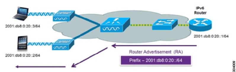
  • The host takes the first 64 bits of the IPv6 prefix from the Router Advertisement message and combines it with the 64-bit EUI-64 address (in the case of Ethernet, this is created from the MAC address) to create a global unicast address. The host also uses the source IP address in the IP header of the Router Advertisement message as its default gateway.

  • IPv6 clients perform Duplicate Address Detection to ensure that randomly chosen addresses do not conflict with those of other clients.

Note

The last 64 bits of the IPv6 address can be learned by using one of these algorithms:

  • EUI-64, which is based on the MAC address of the interface

  • Private addresses that are randomly generated

Figure 1. Address Assignment Using SLAAC


These Cisco IOS configuration commands from a Cisco-capable IPv6 router are used to enable SLAAC addressing and router advertisements:

ipv6 unicast-routing
				interface Vlan20
				description IPv6-SLAAC
				ip address 192.168.20.1 255.255.255.0
				ipv6 address FE80:DB8:0:20::1 linklocal
				ipv6 address 2001:DB8:0:20::1/64
				ipv6 enable
				end

Stateful DHCPv6 address assignment

A stateful DHCPv6 address assignment is an IPv6 address management method that

  • assigns unique IPv6 addresses to clients from a DHCPv6 pool

  • enables the router or external DHCPv6 server to manage address state and lease information, and

  • provides additional configuration details, including domain names and DNS servers.

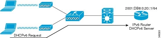
There are two modes of operation for DHCPv6: Stateless and Stateful.

The DHCPv6 Stateless mode is used to provide clients with additional network information that is not available in the router advertisement, but not an IPv6 address, becuase this is already provided by SLAAC. This information includes the DNS domain name, DNS servers, and other DHCP vendor-specific options.

Figure 2. Stateful DHCPv6 Address Assignment

Configure the interface as shown to implement stateless DHCPv6 with SLAAC enabled on your Cisco IOS IPv6 router.

ipv6 unicast-routing
ipv6 dhcp pool IPV6_DHCPPOOL
address prefix 2001:db8:5:10::/64
domain-name cisco.com
dns-server 2001:db8:6:6::1
interface Vlan20
description IPv6-DHCP-Stateless
ip address 192.168.20.1 255.255.255.0
ipv6 nd other-config-flag
ipv6 dhcp server IPV6_DHCPPOOL
ipv6 address 2001:DB8:0:20::1/64
end

Configure DHCP pool on switch (GUI)

Set up DHCP pools to automatically assign IP addresses to devices on your network using the GUI.

Procedure

1.

Choose Administration > DHCP. Click the Add button. The Create DHCP Pool dialog box appears.

2.

Enter a pool name in the DHCP Pool Name field. The pool name must not exceed 236 characters.

3.

Select either IPv4 or IPv6 from the IP Type drop-down list.

4.

Enter an IP address in the Network field.

5.

Select a subnet mask from the Subnet Mask drop-down list.

6.

Enter an IP address in the Starting ip field amd enter an IP address in the Ending ip field.

7.

(Optional) Set the status of the Reserved Only field to Enabled to reserve the DHCP pool. Select the desired option from the Lease drop-down list.

8.

Selecting the User Defined option from the Lease drop-down list enables the (0-365 days), (0-23 hours), and (0-59 minutes) fields. Enter appropriate values. Click the Save & Apply to Device button.

9.

For IPv6, enter the DNS Server, DNS Domain Name, and Ipv6 Address Allocation.


Configure DHCP pool on Switch (CLI)

Set up a DHCP pool so that devices connected to the switch automatically receive IP addresses and network configuration using commands.

Follow the procedure given below to configure DHCP Pool on an interface:

Procedure

1.

Enable the privileged EXEC mode.

Example:

Device# enable

Enter your password if prompted.

2.

Enter the global configuration mode.

Example:

Device# configure terminal
3.

Enter the configuration mode and configure the IPv6 DHCP pool on the VLAN.

Example:

Device(config)# ipv6 dhcp pool vlan-id
4.

Enter the configuration-DHCP mode and configure the address pool and its lifetime on a VLAN.

Example:

Device(config-dhcpv6)# address prefix 2001:DB8:0:1:FFFF:1234::/64 lifetime 300 10
5.

Configure the DNS servers for the DHCP pool.

Example:

Device(config-dhcpv6)# dns-server 2001:20:21::1
6.

Configure the domain name to complete unqualified host names.

Example:

Device(config-dhcpv6)# domain-name example.com
7.

Return to the privileged EXEC mode.

Example:

Device(config)# end

Alternatively, you can also press Ctrl-Z to exit global configuration mode.


Configure stateless auto address configuration without DHCP on Switch (CLI)

Configure IPv6 addresses using stateless auto address configuration without enabling DHCP on the switch using commands.

Procedure

1.

Enable the privileged EXEC mode.

Example:

Device# enable

Enter your password if prompted.

2.

Enter the global configuration mode.

Example:

Device# configure terminal
3.

Create an interface and enter the interface configuration mode.

Example:

Device# interface vlan 1
4.

Configure IPv6 address on the GigabitEthernet interface using the link-local option.

Example:

Device(config-if)# ip address 198.51.100.1 255.255.255.0
Device(config-if)# ipv6 address fe80::1 link-local
Device(config-if)# ipv6 address 2001:DB8:0:1:FFFF:1234::5/64 
Device(config-if)# ipv6 address 2001:DB8:0:0:E000::F/64
5.

(Optional) Enable IPv6 on the GigabitEthernet interface.

Example:

Device(config)# ipv6 enable
6.

Ensure the attached hosts do not use stateful autoconfiguration to obtain addresses.

Example:

Device(config)# interface vlan 1
Device(config-if)# no ipv6 nd managed-config-flag
7.

Ensure the attached hosts do not use stateful autoconfiguration to obtain non-address options from DHCP (domain etc).

Example:

Device(config-if)# no ipv6 nd other-config-flag
8.

Return to the privileged EXEC mode.

Example:

Device(config)# end

Alternatively, you can also press Ctrl-Z to exit global configuration mode.


Configure stateless auto address configuration with DHCP on Switch

Enable IPv6 stateless auto address configuration so attached hosts can receive IPv6 addresses and additional information from DHCP without stateful address assignment using commands.

Procedure

1.

Enable the privileged EXEC mode and enter the global configuration mode.

Example:

Device# enable
Device# configure terminal

Enter your password if prompted.

2.

Create an interface and enter the interface configuration mode.

Example:

Device(config)# interface vlan 1
3.

Configure IPv6 address on the GigabitEthernet interface using the link-local option.

Example:

Device(config-if)# ip address 198.51.100.1 255.255.255.0
Device(config-if)# ipv6 address fe80::1 link-local
Device(config-if)# ipv6 address 2001:DB8:0:1:FFFF:1234::5/64 
Devicec(config-if)# ipv6 address 2001:DB8:0:0:E000::F/64
4.

Configure IPv6 address on the GigabitEthernet interface using the link-local option.

Example:

Device(config-if)# ip address 198.51.100.1 255.255.255.0
Device(config-if)# ipv6 address fe80::1 link-local
Device(config-if)# ipv6 address 2001:DB8:0:1:FFFF:1234::5/64 
Device(config-if)# ipv6 address 2001:DB8:0:0:E000::F/64
5.

(Optional) Enable IPv6 on the GigabitEthernet interface.

Example:

Device(config)# ipv6 enable
6.

Specify a subnet prefix.

Example:

Device(config)# ipv6 nd prefix 2001:9:3:54::/64 no-advertise
7.

Ensure the attached hosts do not use stateful autoconfiguration to obtain addresses.

Example:

Device(config)# interface vlan 1
Device(config-if)# no ipv6 nd managed-config-flag
8.

Ensure the attached hosts do not use stateful autoconfiguration to obtain non-address options from DHCP (domain etc).

Example:

Device(config-if)# no ipv6 nd other-config-flag
9.

Display the configuration parameters and exit the interface mode.

Example:

Device(config)# ipv6 dhcp server servername
Device(config)# end

Configure stateless address auto configuration without DHCP on Switch (CLI)

Set up IPv6 addresses for hosts on a switch using SLAAC, ensuring they do not rely on DHCP for address or configuration using commands.

Procedure

1.

Enable the privileged EXEC mode.

Example:

Device# enable

Enter your password if prompted.

2.

Enter the global configuration mode.

Example:

Device# configure terminal
3.

Create an interface and enter the interface configuration mode.

Example:

Device(config)# interface vlan 1
4.

Configure IPv6 address on the GigabitEthernet interface using the link-local option.

Example:

Device(config-if)# ip address 198.51.100.1 255.255.255.0
Device(config-if)# ipv6 address fe80::1 link-local
Device(config-if)# ipv6 address 2001:DB8:0:1:FFFF:1234::5/64 
Device(config-if)# ipv6 address 2001:DB8:0:0:E000::F/64
5.

(Optional) Enable IPv6 on the GigabitEthernet interface.

Example:

Device(config)# ipv6 enable
6.

Ensure the attached hosts do not use stateful autoconfiguration to obtain addresses.

Example:

Device(config)# interface vlan 1
Device(config-if)# no ipv6 nd managed-config-flag
7.

Ensure the attached hosts do not use stateful autoconfiguration to obtain non-address options from DHCP (domain etc).

Example:

Device(config-if)# no ipv6 nd other-config-flag
8.

Return to the privileged EXEC mode.

Example:

Device(config)# end

Alternatively, you can also press Ctrl-Z to exit global configuration mode.


Router solicitation

A router solicitation message is a network communication signal that

  • is issued by a host controller to locate local routers

  • prompts routers to transmit Router Advertisement messages, and

  • facilitates the host in obtaining routing information or performing stateless auto-configuration.

Router Advertisements are transmitted periodically. The host triggers an immediate Router Advertisement using a Router Solicitation, for example, when it boots or after a restart operation.


Router advertisement

A Router advertisement is a type of message

  • that is sent by IPv6 routers either periodically or in response to Router Solicitation messages from hosts, and

  • communicates essential information such as network prefixes, default gateway availability, and configuration flags.

Router advertisement messages enable hosts to perform stateless autoconfiguration and update their routing tables with current network settings.


Router advertisement guard

A router advertisement guard is a security feature that

  • examines incoming router advertisement messages from IPv6 devices

  • drops unwanted or rogue router advertisements coming from wireless clients, and

  • protects legitimate IPv6 routers and the network from misconfigured or malicious IPv6 clients.

By default, RA guard is always enabled on the controller.

  • Port on which the frame is received

  • IPv6 source address

  • Prefix list

  • Trusted or Untrusted ports for receiving the router advertisement guard messages

  • Trusted/Untrusted IPv6 source addresses of the router advertisement sender

  • Trusted/Untrusted Prefix list and Prefix ranges

  • Router preference


Router advertisement throttling

A router advertisement throttle is a network control mechanism that

  • enforces limits on the frequency of router advertisement (RA) packets sent toward the wireless network

  • ensures routers that send multiple RA packets are restricted to a minimum frequency required for IPv6 client connectivity, and

  • maintains uninterrupted IPv6 connectivity for new or roaming clients by allowing RA packets in response to Router Solicitation (RS) packets.

If a client sends an RS packet, the router sends an RA back to the client. The controller allows this RA to pass and delivers it as a unicast message to the client. This process ensures that new or roaming clients are not affected by RA throttling.


Configure RA throttle policy (CLI)

Restrict the frequency and quantity of multicast Router Advertisements (RAs) sent to wireless clients for improved network performance and client behavior using commands.

Configure RA Throttle policy to allow the enforce the limits

Procedure

1.

Enter the global configuration mode.

Example:

Device# configure terminal
2.

Define the router advertisement (RA) throttler policy name and enter IPv6 RA throttle policy configuration mode.

Example:

Device(config)# ipv6 nd ra-throttler policy ra-throttler1
3.

Configure the throttle period in an IPv6 RA throttler policy.

Example:

Device(config-nd-ra-throttle)# throttle-period 500
The throttle period is measured in seconds. It is the duration during which the controller does not forward RA to wireless clients.
4.

Limit multicast RAs per VLAN per throttle period.

Example:

Device(config-nd-ra-throttle)# max-through 15
5.

Limit the number of multicast RAs per device per throttle period in an RA throttler policy.

Example:

Deviceconfig-nd-ra-throttle)# allow at-least 5 at-most 10

Apply RA throttle policy on VLAN (GUI)

Apply a Router Advertisement (RA) throttle policy to a VLAN through the GUI to control the rate of RA packets on your network.

Procedure

1.

Choose Configuration > Services > RA Throttle Policy.

2.

Click Add. The Add RA Throttle Policy dialog box appears.

3.

Enter a name for the policy in the Name field.

4.

Select the desired option from the Medium Type drop-down list.

5.

Enter a value in the Throttle Period field. RA throttling takes place only after the Max Through limit is reached for the VLAN or the Allow At-Most value is reached for a particular router.

6.

Enter a value for the Max Through field, which is the maximum number of RA packets on a VLAN that can be sent before throttling takes place. The No Limit option allows an unlimited number of RA packets through with no throttling.

7.

Choose an Interval Option. The device acts differently based on the RFC 3775 value set in IPv6 RA packets. Options include:

  • Ignore: Causes the RA throttle to treat packets with the interval option as a regular RA and subjects them to throttling if in effect.

  • Passthrough: Allows any RA messages with the RFC 3775 interval option to go through without throttling.

  • Throttle: Causes the RA packets with the interval option to always be subject to rate limiting.

8.

Enter the minimum number of RA packets per router that can be sent as multicast before throttling takes place in the At Least Multicast RAs field.

9.

Enter the maximum number of RA packets per router that can be sent as multicast before throttling takes place in the At Most Multicast RAs field. The No Limit option allows an unlimited number of RA packets through the router. Click the Add & Apply to Device button.


Apply RA throttle policy on a VLAN (CLI)

Control and optimize IPv6 Router Advertisement (RA) packet frequency within a VLAN, ensuring efficient IPv6 client connectivity using commands.

Applying the RA Throttle policy on a VLAN. Enabling RA throttling reduces the frequency of router advertisement packets while still maintaining IPv6 client connectivity.

Procedure

1.

Enter the global configuration mode.

Example:

Device# configure terminal
2.

Configure a VLAN or a collection of VLANs and enter the VLAN configuration mode.

Example:

Device(config)# vlan configuration 1
3.

Attach an IPv6 RA throttler policy to a VLAN or a collection of VLANs.

Example:

Device(config-vlan)# ipv6 nd ra throttler attach-policy ra-throttler1

Neighbor discovery

IPv6 Neighbor Discovery (ND) is a suite of messages and processes

  • that allows devices on an IPv6 network to discover neighbors, determine their link-layer addresses, identify routers, and

  • maintain information about routes and reachability replacing several IPv4 mechanisms, including the Address Resolution Protocol (ARP), ICMP Router Discovery, and ICMP Redirect.

IPv6 neighbor discovery inspection analyzes neighbor discovery messages to build a trusted binding table database. IPv6 Neighbor Discovery packets that do not comply with requirements are dropped. The neighbor binding table in the tracks each IPv6 address and its associated MAC address. The table removes clients according to the neighbor-binding timers.


Neighbor discovery suppression

A neighbor discovery suppression mechanism is a network optimization feature that

  • caches IPv6 addresses of wireless clients when they reach RUN state

  • selectively converts multicast Neighbor Solicitation (NS) requests to unicast or replies directly, depending on configuration, and

  • forwards NS multicast requests to the wired side when the target address is not in the device’s cache.

The same behavior applies to ARP requests for IPv4 addresses, where the device maintains the IPv4 address of the wireless client in the cache.

If neither configuration is enabled, and the device receives a Non-DAD or DAD NS multicast searching for an IPv6 address, and the target address is known to the device and belongs to one of its clients, the device converts the multicast NS to a unicast NS. It replaces the destination MAC address with the client’s MAC address and forwards the unicast packet to the client.

If full proxy is enabled, and the device receives a Non-DAD or DAD NS multicast searching for an IPv6 address, and the target address is known to the device and belongs to one of its clients, the device replies with an NA message on behalf of the client.

Use the ipv6 nd proxy command to enable or disable DAD or full proxy.

When the device receives an DAD-NS multicast looking for an IPv6 address, and if the target address is known to the device and belongs to one of its clients, the device will reply with an NA message on behalf of the client.

If the device receives a DAD-NS multicast searching for an IPv6 address, and the target address is known to the device and belongs to one of its clients, the device replies with an NA message on behalf of the client.

If the device does not have the IPv6 address of a wireless client, it does not respond with NA; instead, it forwards the NS packet to the wired side. This is because all wireless client IPv6 addresses and their corresponding MAC addresses should be available in the controller. If an IPv6 address required by the NS is not available, the address is assumed not to belong to a wireless client, so the request is forwarded to the wired side.