Cisco Catalyst 9800 Series Wireless Controller Software Configuration Guide, Cisco IOS XE 26.1.x

PDF

Cisco Catalyst 9800 Series Wireless Controller Software Configuration Guide, Cisco IOS XE 26.1.x

High Availability

Want to summarize with AI?

Log in

This topic explains High Availability (HA) and how it reduces wireless network downtime by enabling seamless failover between controllers, ensuring continuous service for APs and clients.


A high availability feature is a wireless controller capability that

  • reduces network downtime by enabling seamless failover between active and standby controllers,

  • preserves AP and client connectivity through stateful switchover by maintaining CAPWAP tunnels and client sessions during failover, and

  • mirrors AP and client databases from the active controller to the standby controller to prevent APs from entering discovery state and avoid client disconnections.

Feature history for High Availability

This table provides release and related information for the features explained in this module.

These features are available in all the releases subsequent to the one they were introduced in, unless noted otherwise.

Table 1. Feature history

Release

Feature

Feature information

Cisco IOS XE 17.18.1

Enhanced Gateway Reachability Statistics

Improves visibility into gateway reachability and provides detailed statistics for ICMP, ARP, and ND probes. This feature enables simplified troubleshooting, greater transparency, and more reliable diagnostics for HA and RMI functionality.

This command is introduced:

  • show platform software rif-mgr chassis { active | standby} r0 gateway-statistics

This command is modified:

  • show platform software rif-mgr chassis { active | standby} r0 resource-status

Cisco IOS XE 17.9.1

High Availability Deployment for Application Centric Infrastructure (ACI) Network

This feature avoids interleaving traffic between the old and new active controller using these functionalities:

  • Bringing down Wireless Management Interface (WMI) faster.

  • Disabling fast switchover notification.

Link Layer Discovery Protocol (LLDP) Support in the Standby Controller

From this release, the Link Layer Discovery Protocol (LLDP) process will be up and running in both active and standby controllers.

Cisco IOS XE 17.6.1

Standby Interface Status using Active SNMP

This feature allows the standby controller interface status to be queried at the active using SNMP.

Cisco IOS XE 17.5.1

Auto-Upgrade

The auto-upgrade feature enables the standby controller to upgrade to active controller's software image, so that both controllers can form an high availability (HA) pair.

Cisco IOS XE 17.5.1

Standby Monitoring Enhancements

The Standby Monitoring Enhancements feature monitors the standby CPU or memory information from the active controller. Also, this feature independently monitors the standby controller using SNMP for the interface MIB.

The cLHaPeerHotStandbyEvent and cLHaPeerHotStandbyEvent MIB objects in CISCO-HA-MIB are used to monitor the standby HA status.

Cisco IOS XE 17.4.1

Gateway Reachability Detection

Gateway reachability feature minimizes the downtime on APs and clients when the gateway reachability is lost on the active controller.

Cisco IOS XE 17.1.1s

Redundant Management Interface

The Redundancy Management Interface (RMI) is used as a secondary link between the active and standby controllers. This interface is the same as the Wireless Management Interface and the IP address on this interface is configured in the same subnet as the Wireless Management Interface.

Additional reference information

High availability enables seamless controller failover, ensuring that APs and clients remain connected during controller outages. These notes and recommendations apply to HA deployments:

  • Do not shut or unshut the RP port during controller bootup in HA mode.

  • If RP communication is lost between the active and standby controllers during HA synchronization, the standby controller intentionally crashes when IPC communication fails.

    If the RP link is restored, the standby controller restarts gracefully and forms an HA pair.

  • When the controller operates as a spanning tree host, configure portfast trunk on the uplink switch to ensure faster convergence. Use spanning-tree port type edge trunk or spanning-tree portfast trunk.

  • You can configure FIPS in an HA setup. For information, see the Configuring FIPS in HA Setup.

  • Do not configure the secondary IPv4 address. The controller uses the IPv4 secondary address internally for RMI purposes.

    Configure only one management IPv6 address on the Wireless Management Interface (WMI). The controller uses any secondary address for RMI-IPv6.

    Configuring more than one management IPv4 address or more than one management IPv6 address on the WMI may cause unpredictable behavior.

During a failover event, only one CAPWAP tunnel is maintained between APs and the active controller. This ensures zero downtime for client services and no SSID outages. Database mirroring prevents APs from entering the discovery state and ensures that clients remain connected without interruption.


Prerequisites for High Availability

To ensure high availability, configure interfaces properly, select the appropriate HA port, and meet latency, bandwidth, and MTU requirements for RP links.

External interfaces and IPs

All interfaces are configured on the Active box and synchronized with the Standby box. Therefore, the same set of interfaces is present on both controller s.

External nodes connect to the same IP addresses regardless of which controller they are connected to.

APs, clients, DHCP servers, Cisco Prime Infrastructure, Cisco Catalyst Center, and Cisco Identity Services Engine (ISE) servers, as well as other controller members in the mobility group, always connect to the same IP address.

The SSO switchover is transparent to these devices. However, if TCP connections exist from external nodes to the controller , reset and reestablish those connections.

HA interfaces

The HA interface provides:

  • Provides connectivity between the controller pair before an IOSd comes up,

  • provides IPC transport across the controller pair, and

  • enables redundancy across control messages exchanged between the controller pair. The control messages include HA role resolution, keepalive messages, notifications, HA statistics, and similar messages.

You can select an SFP or RJ-45 connection for the HA port. Supported Cisco SFPs are:

  • GLC-SX-MMD

  • GLC-LH-SMD

Note

Connect either the SFP port or the RJ-45 port to the peer. Do not connect both ports at the same time.

HA operates when either an SFP or RJ-45 connection is present between the two controllers. If you connect an SFP link while RJ-45 HA is active, the HA pair restarts. The restart occurs even if the SFP link is not connected.

Note
  • Use a dedicated physical network interface card (NIC) and switch for the redundancy port (RP) when deploying the HA pair across two hosts. This prevents keepalive losses and false HA switchovers or alarms.

  • Disable security scans on VMware virtual instances to prevent HA issues.

Note

Connect RP links using switches to enable controller HA. Keep the round-trip time between the two controllers under 80 milliseconds.

Latency, bandwidth, and MTU

These are the latency, bandwidth, and MTU prerequisites for the RP link:

  • The maximum supported latency for the RP link is 80 milliseconds round-trip time (RTT).

  • The RP link must support a minimum bandwidth of 60 megabits per second (Mbps).

  • The RP link must support a minimum maximum transmission unit (MTU) of 1500 bytes.


High Availability restrictions

  • Wait until configuration synchronization completes on the standby controller. Before initiating a fail-safe Stateful Switchover (SSO), ensure that the standby controller has been powered on for sufficient time (up to 24 minutes [up to 1,440 seconds] on some platforms) to achieve readiness. Use the show wireless stats redundancy config database command to view database statistics.

  • During a switchover in local mode, NBAR engine flow states are lost. As a result, classification restarts and may lead to incorrect packet classification.

  • You can use HA connections only with IPv4.

  • When you perform a switchover or an active reload, the high-availability link goes down on the new primary controller.

  • Do not enable hyper-threading in HA systems. If enabled, HA keepalives are lost, and a stack merge may occur.

  • You cannot access the web UI from the standby RMI interface.

  • Configure two HA interfaces, RMI and RP, on the same subnet. Do not share this subnet with any other interfaces on the device.

  • After a switchover, you must re-establish any TCP session because synchronization is not possible.

  • Client SSO does not address clients that have not reached the RUN state. These clients are removed after a switchover.

  • Statistics tables are not synchronized from the active controller to the standby controller.

  • Creating a machine snapshot of a VM hosting controller HA interfaces is not supported. This action may lead to a crash in the HA controller.

  • Clients that are not in RUN state are reauthenticated after a switchover.

  • Application classification may not be retained after SSO:

    • AVC limitation—After a switchover, context transfer or synchronization to the standby controller does not occur. The new active flow must be relearned. AVC QoS does not take effect during classification failure.

    • A voice call cannot be recognized after a switchover because a voice policy is based on RTP or RTCP protocol.

    • Auto QoS does not work due to AVC limitation.

  • For virtual platforms, pair the active controller and the standby controller with the same interface. For hardware appliances, use a dedicated HA port.

  • You can synchronize static IP addressing to the standby controller, but you cannot use the IP address from the standby controller.

  • You can map a dedicated HA port to a 1-gigabit (1,000 Mbps) interface only.

  • To use EtherChannels in HA mode in releases up to Cisco IOS XE Gibraltar 16.12.x, ensure that the channel mode is set to On.

  • EtherChannel Auto-mode is not available in HA mode in releases up to Cisco IOS XE Gibraltar 16.12.x.

  • LACP and PAGP protocols cannot be used in HA mode in releases up to Cisco IOS XE Gibraltar 16.12.x.

  • When the controller operates as a host for spanning tree, configure portfast trunk on the uplink switch using spanning-tree port type edge trunk or spanning-tree portfast trunk command to ensure faster convergence.

  • The clear chassis redundancy and write erase commands do not reset the chassis priority to the default value.

  • While configuring devices in HA, ensure that members do not have wireless trustpoints with the same name but different keys. If you form an HA pair between two standalone controllers with mismatched trustpoints, the wireless trustpoint does not come up after SSO. The rsa keypair file exists but is incorrect because the nvram:private-config file is not synchronized with the actual WLC_WLC_TP key pair.

  • Before forming HA, delete existing certificates and keys from each controller that was previously deployed as standalone. This is a best practice.

  • Do not configure the WLAN or WLAN policy after a switchover while recovery is in progress. Doing so may cause the controller to crash.

  • After a switchover, clients that are not in RUN state and not connected to an AP are removed after 300 seconds (5 minutes).


Best practices for RP port configuration

When you configure RP ports, use these best practices:

  • Ensure that the Local and Remote IP addresses are in the same subnet.

  • Use the 169.254.X.X/16 subnet, deriving the last two octets from the management interface.

  • Do not use the 10.10.10.x/24 subnet for the RP port.

  • For more information about RMI+RP chosen as the redundancy method, see Information About Redundancy Management Interface .


Configure High Availability (CLI)

Set up high availability for network redundancy and automatic failover between devices using the CLI.

Before you begin

Ensure that the active and standby controllers use the same mode—either Install mode or Bundle mode—and the same image version. Use Install mode.

Procedure

1.

(Optional) Configure the priority of the device.

Example:

Device# chassis chassis-num priority chassis-priority
Note

From Cisco IOS XE 16.12.x onward, a device reload is not required for the chassis priority to take effect.

  • chassis-num —Enter the chassis number (range: one to two).

  • chassis-priority —Enter the chassis priority (range: one to two; default: one).

Note

If both devices boot up simultaneously, the device with the higher priority (2) becomes active. The other device becomes standby. If both devices have the same priority, the device with the smaller MAC address becomes active, and the peer device becomes standby.

2.

Set the chassis high-availability parameters.

Example:

Device# chassis redundancy ha-interface GigabitEthernet num local-ip local-chassis-ip-addr network-mask remote-ip remote-chassis-ip-addr

Example:

Device# chassis redundancy ha-interface 
                        GigabitEthernet 2 local-ip 4.4.4.1 /24 remote-ip 4.4.4.2
  • num —GigabitEthernet interface number (range: zero to 32).

  • local-chassis-ip-addr —Enter the IP address of the local chassis high-availability interface.

  • network-mask —Enter the network mask or prefix length in slash nn or dotted decimal format.

  • remote-chassis-ip-addr —Enter the remote chassis IP address.

This command is not supported on these models:

  • Cisco Catalyst CW9800H1 Wireless Controller.

  • Cisco Catalyst CW9800H2 Wireless Controller.

  • Cisco Catalyst CW9800M Wireless Controller.

RMI-based high availability is mandatory in the Cisco Catalyst CW9800H1 Wireless Controller, Cisco Catalyst CW9800H2 Wireless Controller, and Cisco Catalyst CW9800M Wireless Controller.

3.

Configure the peer keepalive timeout value.

Example:

Device# chassis redundancy keep-alive timer timer

Set the time interval in multiples of 100 milliseconds (ms). Enter one for the default value.

4.

Set the peer keepalive retry value that determines when the system considers the peer down.

Example:

Device# chassis redundancy keep-alive retries retry-value

The default value is five.

After you complete these steps, high availability is configured between two devices. The system uses device priorities, high-availability interfaces, and keepalive parameters to ensure redundancy and seamless failover if a device fails.


Disable High Availability

When you disable high availability, all HA-related parameters are removed and the controller returns to stand-alone mode.

  • Use clear chassis redundancy with the RP method to clear the local IP, remote IP, HA interface, mask, timeout, and priority.

  • Use no redun-management interface vlan chassis with the RMI method.

  • After you unpair the controllers, the startup and HA configuration of the standby controller are cleared, and it enters Day zero state.

If you configure the controller using the RP method for SSO, use this command to clear all HA-related parameters: local IP, remote IP, HA interface, mask, timeout, and priority:

  • clear chassis redundancy

If you configure the controller using the RMI method, use this command:

  • no redun-management interface vlan chassis

Note

This command is not supported on these models:

  • Cisco Catalyst CW9800H1 Wireless Controller .

  • Cisco Catalyst CW9800H2 Wireless Controller .

  • Cisco Catalyst CW9800M Wireless Controller .

Note

Reload your devices to apply the changes.

Before you execute the command, you see this warning on the active controller:


Device# clear chassis redundancy
WARNING: Clearing the chassis HA configuration will result in both the chassis move into
Stand Alone mode. This involves reloading the standby chassis after clearing its HA
configuration and startup configuration which results in standby chassis coming up as a totally
clean after reboot. Do you wish to continue? [y/n]? [yes]:
*Apr 3 23:42:22.985: received clear chassis.. ha_supported:1yes
WLC#
*Apr 3 23:42:25.042: clearing peer startup config
*Apr 3 23:42:25.042: chkpt send: sent msg type 2 to peer..
*Apr 3 23:42:25.043: chkpt send: sent msg type 1 to peer..
*Apr 3 23:42:25.043: Clearing HA configurations
*Apr 3 23:42:26.183: Successfully sent Set chassis mode msg for chassis 1.chasfs file updated
*Apr 3 23:42:26.359: %IOSXE_REDUNDANCY-6-PEER_LOST: Active detected chassis 2 is no
longer standby

On the standby controller, these messages indicate that the configuration is being cleared:

Device-stby#
*Apr 3 23:40:40.537: mcprp_handle_spa_oir_tsm_event: subslot 0/0 event=2
*Apr 3 23:40:40.537: spa_oir_tsm subslot 0/0 TSM: during state ready, got event 3(ready)
*Apr 3 23:40:40.537: @@@ spa_oir_tsm subslot 0/0 TSM: ready -> ready
*Apr 3 23:42:25.041: Removing the startup config file on standby
!Standby controller is reloaded after clearing the chassis.

System and network fault handling

If the standby controller crashes, it reboots and comes up as the standby controller. Bulk sync follows causing the standby to become hot. If the active controller crashes, the standby becomes active. The new active controller assumes the role of primary and tries to detect a dual active.

These matrices provide a clear picture of the conditions the controller switchover would trigger:

Table 2. System and Network Fault Handling after 17.5

Number

RP Link

Reachability Through RMI

GW From Active

GW From Standby

SSO

Result

Additional Information

1

Up

P-Reachable

G-Reachable

G-Reachable

No SSO

No Action

2

Up

P-Reachable

G-Reachable

G-Unreachable

No SSO

No action is required. The standby unit is not ready for SSO in this state because it does not have gateway reachability. In this scenario, the standby unit appears in standby-recovery mode.

Spring Back:

If the gateway reachability is restored (G_Reachable), the controller returns to Standby state (no reboot is necessary).

Note

RP resources and gateway resources each trigger distinct actions.

Spring Back: If the gateway reachability is restored (G_Reachable), the controller transitions to Standby state. A reboot is not required.

3

Up

P-Reachable

G-Unreachable

G-Reachable

SSO

The system exchanges gateway reachability messages over the RMI and RP links. When the active controller reboots, the standby controller takes over as the active controller. The RP goes down during the reboot process.

The Stack Manager sends a message to the standby controller to initiate a role change. The standby controller consults the active controller.

  • If the active controller responds, the standby controller determines that the active controller does not have all the required resources and allows the role change.

  • If the active controller does not respond, or if the RMI link is down, the standby controller proceeds with the role change because it has all the resources required to become active.

4

Up

P-Reachable

G-Unreachable

G-Unreachable

No SSO

The standby controller is not ready for SSO in this state because it does not have gateway reachability. The standby controller appears in Standby-Recovery mode.

SpringBack:

If the gateway reachability is restored on the Standby-Recovery controller (G_Reachable), the controller transitions to the standby state.

5

Up

P-Unreachable

G-Reachable

G-Reachable

No SSO

No action taken when RMI goes DOWN. There will be no DAD when the RMI link is DOWN.

If gateway reachability (G_Reachable) is lost, the controller transitions to Standby. This situation is managed as case (3)

The active controller maintains its state when gateway reachability is lost.

No action is taken when the RMI link goes down.

Dual-Active Detection (DAD) does not occur when the RMI link is down.

6

Up

P-Unreachable

G-Reachable

G-Unreachable

No SSO

No Action. Standby is not ready for SSO in this state as it does not have gateway reachability. The standby shall be shown to be in standby-recovery mode.

Spring Back: If the gateway reachability is restored (G_Reachable), the controller shall go to Standby mode without a reload.

There shall be no action if the RMI comes UP.

7

Up

P-Unreachable

G-Unreachable

G-Reachable

SSO

A gateway reachability message is also exchanged over the RP link. The Active device reboots so that the Standby device becomes the new Active. The RP link goes down when the Active device reboots. The Stack Manager sends a message over the RP and RMI links to the Standby Controller to initiate the role change. The Standby controller consults the Active device.

  • If the Active responds, the Standby determines that the Active does not have all resources and allows the role change.

  • If the Active does not respond—possibly because the RP link is already down—the Standby allows the role change regardless of resource status.

When the active controller reboots, the RP goes down. The Stack Manager sends a message over the RP and RMI link to the standby controller to initiate a role change. The standby controller consults the active controller.

8

Up

P-Unreachable

G-Unreachable

G-Unreachable

No SSO

The standby controller is not ready for SSO in this state because it does not have gateway reachability. The standby controller appears in standby-recovery mode.

Spring Back:

If gateway reachability is restored on the standby-recovery controller (G_Reachable), the controller transitions to standby. Refer to step 7 for more details.

The active controller does not change its state when gateway reachability is lost.

No action occurs if the RMI comes up.

When the Active device reboots, the RP goes down. The Stack Manager sends a message over the RP and RMI links to the Standby Controller to initiate a role change.

The Standby Controller consults the Active Controller.

  • If the Active responds, the Standby deduces that the Active does not have all the required resources and proceeds with the role change.

  • If the Active does not respond (for example, if the RP is already down), the Standby allows the role change regardless of the resource status.

9

Down

P-Reachable

G-Reachable

G-Reachable

No SSO

When the RP is not available, the standby transitions to Standby-Recovery mode. The stack manager requests a role change when the RP goes down. If the RMI is up, the RIF manager sends a message to the active unit to check its status. If a response is received, the standby does not allow the role change and transitions to Standby-Recovery. If there is no response, such as when the active unit is down due to a crash, the role change is allowed.

This scenario works differently if the RP goes down before the standby reaches Standby-Hot state. If the RP link goes down before the standby becomes Standby-Hot, the RIF sends a positive response to the stack manager, resulting in a controller reload.

Spring Back:

If gateway reachability is restored on the Standby-Recovery (G_Reachable), the controller transitions to Standby. In this case, refer to state (7). The Active controller does not change its state when gateway reachability is lost. No action is taken if the RMI comes up.

10

Down

P-Reachable

G-Reachable

G-Unreachable

No SSO

The standby is not ready for SSO in this state because it does not have gateway reachability. The standby will appear in standby-recovery mode.

There are two possible scenarios:

  • The RP goes down first, followed by the standby gateway.

  • The standby gateway goes down first, followed by the RP.

Consider the case where the RP goes down first. In this situation, the stack manager requests a role change. However, because the standby does not have gateway reachability, it cannot allow the role change. The system starts a 30-minute timer when the RMI goes down (meaning both the RP and RMI are down).

If the RP goes down before the standby is in standby-hot state, the system reloads. There are several sub-cases:

  • If the active unit crashes and returns within 30 minutes, the timer stops. The standby remains in recovery and reboots when the RP is up.

  • If the RP stays down, no action is taken when the timer expires, provided the RMI is up.

  • If the active unit continuously crashes, the timer expires with the RMI down, and the standby-recovery unit reboots as the active unit.

Spring Back:

  • If the gateway returns first, the standby-recovery unit remains in recovery.

  • If the RP returns first, the system reboots to standby-recovery or standby, depending on whether the gateway is reachable.

When the RP goes down, the stack manager requests a role change. While the RMI is operational, the RIF manager sends a message to the active controller to verify its status. If a response is received, the standby controller prevents the role change and transitions to standby-recovery. If there is no response, such as when the active controller is down due to a crash, the role change is permitted.

However, if the RP goes down before the standby controller reaches the standby-hot state, the RIF manager sends a positive response to the stack manager, which results in a controller reload.

11

Down

P-Reachable

G-Unreachable

G-Unreachable

No SSO

Standby transitions to Standby-Recovery. Assume both controllers lose gateway, then RP goes down. Stack manager requests a role change. Because Standby lacks resources, it starts a 30-minute timer when RMI goes down (that is, RP and RMI are both down).

There are three possible outcomes:

  • If Active recovers within 30 minutes, the timer stops. Standby remains in recovery and may reboot when RP returns.

  • If RP stays down, no action occurs when the timer expires, provided RMI is up.

  • If Active never recovers, the timer expires with RMI down, and Standby-Recovery reboots as Active.

  • If Active never recovers, the timer expires with RMI down, and Standby-Recovery reboots as Active.

Note

If gateway reachability was not enabled, SSO is not allowed when Active is up. If Active is down and Standby is standby-hot, SSO is allowed. If RP returns before standby-hot, it reloads. Note: Recovery to Standby without reload is possible only if recovery was due solely to gateway.

Spring Back:

  • If gateway returns first, the system remains in Standby-Recovery.

  • If RP returns first, the system reboots to Standby-Recovery and then to Standby if gateway is up.

Let us assume that both the controllers lost their GW and then the RP went DOWN.

The stack manager will request for a role change when the RP goes DOWN. The standby anyway does not have all resources (Gateway Reachability at present) and hence it shall not allow role change to happen. It will start the 30 min timer when RMI goes DOWN( timer starts when RP+RMI are DOWN).There are now two possibilities:

  • The active suffered a software glitch (For example: a crash) in which case, it would come up within 30 minutes and the timer would be stopped. The standby will continue to be in standby-recovery. If the RP comes UP when the timer is running, the Standby-Recovery would reboot and might come up as Standby or Standby-Recovery.

  • Physical RP connection went down and it remains down. When the timer expires, if the RMI is UP, no action shall be taken.

  • The active continuously crashes, that is, it does not come up after 30 minutes. In this case, when the timer expires,the RMI will be DOWN. The standby-recovery shall reboot when the timer expires (and might come UP as Active.)

When RP DOWN event is received, if the Gateway Reachability is not enabled, Gateway will not be considered as a resource. In this case, SSO shall not be allowed if the Active is UP. SSO shall be allowed if Active is DOWN, provided Standby is in Standby-Hot state.

If the RP link goes down before the standby becomes standby-hot, it shall reload.

Note

The Standby-Recovery that has lost RP is no more Standby Hot. This implies that the recovery from Standby-Recovery to Standby without a reboot (as was the case earlier in 17.2) is not possible for RP events. It is however possible for Gateway events.

Spring Back:

  • When the Standby-Recovery findsGateway is UP it continues to be in Standby-Recovery if RP is still DOWN.

  • When the Standby-Recovery finds that its RP is UP, it will reboot and come up as Standby-Recovery

13

Down

P-Unreachable

G-Reachable

G-Reachable

SSO

A double fault may result in two active controllers. When this occurs, the Standby controller becomes active, but the original Active controller may still exist. Once connectivity is restored, role negotiation ensures that the most recent Active controller is retained.

In the event that RMI goes down and then RP also goes down, the stack manager requests a role change. If RMI is unavailable, Standby grants the role change only if it is in standby-hot mode; otherwise, it denies the request. If RP returns before standby-hot mode is reached, it reloads.

Spring Back:

If RMI returns, the previous Active controller enters Active-Recovery mode. When RP returns, the controller reboots and transitions to Standby. If RP goes down, RMI goes down, and the timer expires, Standby reboots as Active. The timer may be skipped in cases of a pure double fault.

Note
You may skip the timer for pure double-fault cases.

Let us assume that the RMI goes DOWN first and then the RP goes DOWN. When the RP goes DOWN, the stack manager requests a role change. Since the RMI is DOWN, the standby cannot consult with the Active. The standby allows a role change to become Active, regardless of its resource state, provided the standby is in Standby-Hot. If the standby is not in Standby-Hot, a role change is not allowed. If the RP link goes down before the standby becomes Standby-Hot, the standby reloads

Spring Back:

If the RMI comes UP at any time, Old Active transitions to Active-Recovery. Active-Recovery reboots when the RP comes up, after which it will become Standby.

If the RP goes DOWN first, refer to case (9). If RP_DOWN and RMI_DOWN occur in that sequence and the 30-minute timer expires, the standby shall reboot. It will come up as Active if RP and RMI continue to be DOWN. Alternatively, the 30-minute timer may not be started in this case.

The timer can be used when the standby does not have all required resources, such as gateway reachability at present or port status and gateway reachability in the future, to take over as Active.

Note

Another option is to not start the 30-minute timer in this situation. Use the timer only if the standby does not have all the required resources to take over as active. Currently, this refers to gateway reachability; in the future, it may also include port status and gateway reachability.

14

Down

P-Unreachable

G-Reachable

G-Unreachable

No SSO

Double fault – two active controllers possible. Old Active stays Active; Standby may become Active if connectivity is not restored within a set time. If Standby is in standby-recovery due to GW loss, then RMI goes down, then RP goes down. Stack manager requests role change; no RMI means no consult, so Standby allows change. If Active crashed, it restarts as Standby; if both come up, split-brain conflict may occur.

Let us assume that the Standby is in Standby-Recovery mode as it loses GW.

Let us assume that the RMI goes DOWN first and then the RP goes DOWN.

The stack manager shall request role change when the RP goes DOWN. Since the RMI isDOWN, the standby cannot consult with the Active. The standby shall allow role change.

Spring Back:

If RMI returns, Old Active enters Active-Recovery and reboots on RP return to become Standby

15

Down

P-Unreachable

G-Unreachable

G-Reachable

SSO

Double fault – two active controllers possible. Standby becomes active; old Active may still exist. Role negotiation occurs once connectivity is restored. Assume GW loss on Active, then RMI down then RP down. Stack manager requests role change; no RMI means standby allows change if in standby-hot, else reloads. If RP returns before standby-hot, it reloads.

Spring Back:

If RMI returns, old Active goes to Active-Recovery and reboots on RP return to become Standby.

Suppose the Standby is in Standby-Recovery mode after losing GW. Assume the RMI goes down first, then the RP goes down. The stack manager requests a role change when the RP goes down. Because the RMI is down, the Standby cannot consult with the Active, so it allows the role change. If the Active went down due to a software glitch, it will come up and become Standby. If no communication is established between the two controllers, both may become active, causing a network conflict

Spring Back:

If the RMI comes UP at some point of time,Old Active will go to Active-Recovery. Active-Recovery shall reboot when the RP comes up and will become Standby.

16

Down

P-Unreachable

G-Unreachable

G-Unreachable

No SSO

A double fault can result in two active controllers. The old Active remains Active, and the Standby may become Active if connectivity is not restored within a stipulated time.

If both controllers lose GW and the Standby is in standby-recovery, then RMI goes down, followed by RP going down. The stack manager requests a role change. If there is no RMI, the Standby allows the change, which can cause a conflict.

Spring Back:

If RMI returns, the old Active enters Active-Recovery and, when RP returns, reboots to become Standby.

Assume that both Active and Standby lose GW, and Standby enters Standby-Recovery. If RMI goes DOWN first, followed by RP going DOWN, the stack manager requests a role change when RP goes DOWN. Since RMI is DOWN, Standby cannot consult with Active and allows the role change. This situation can cause a network conflict.

Spring Back:

If RMI comes UP at any point, the old Active transitions to Active-Recovery. Active-Recovery reboots when RP comes UP and then becomes Standby.


Handling recovery mechanism

This topic provides details about the Active-to-Active and Standby-to-Standby High Availability (HA) recovery mechanisms and the system behaviors for each scenario.

Active-to-Active recovery

  • Active recovery occurs if the Route Processor (RP) is down but the Redundancy Management Interface (RMI) is up during boot. The system triggers active recovery after startup.

  • In a stable active–standby HA state, if RMI goes down followed by RP, and RMI recovers before RP, the system enters Active-to-Active recovery. After RP is restored, the system reloads active recovery and re-establishes HA.

Standby-to-Standby recovery

  • If the Gateway fails, the standby node enters standby recovery mode. In this mode, the standby node stays synchronized with the active unit but cannot become active without the Gateway. When in a hot state, the standby node is ready to take over when Gateway connectivity resumes.

  • If only the Gateway is unavailable, restore the Gateway to allow HA to recover without rebooting.

  • If a Route Processor (RP) failure triggers standby recovery, wait for the RP to return online. The standby node then reboots automatically, and the system restores HA.


Verify high availability configurations

To view the HA configuration details, use this command:

Device# show romvar
ROMMON variables:
 LICENSE_BOOT_LEVEL =
 MCP_STARTUP_TRACEFLAGS = 00000000:00000000
 BOOTLDR =
 CRASHINFO = bootflash:crashinfo_RP_00_00_20180202-034353-UTC
 STACK_1_1 = 0_0
 CONFIG_FILE =
 BOOT = bootflash:boot_image_test,1;bootflash:boot_image_good,1;bootflash:rp_super_universalk9.vwlc.bin,1;
 RET_2_RTS =
 SWITCH_NUMBER = 1
 CHASSIS_HA_REMOTE_IP = 10.0.1.9
 CHASSIS_HA_LOCAL_IP = 10.0.1.10
 CHASSIS_HA_LOCAL_MASK = 255.255.255.0
 CHASSIS_HA_IFNAME = GigabitEthernet2
 CHASSIS_HA_IFMAC = 00:0C:29:C9:12:0B
 RET_2_RCALTS =
 BSI = 0
 RANDOM_NUM = 647419395

Verify AP or client SSO statistics

To view the AP SSO statistics, use this command:

Device# show wireless stat redundancy statistics ap-recovery wnc all
AP SSO Statistics                                                     

Inst    Timestamp     Dura(ms)   #APs  #Succ  #Fail  Avg(ms)  Min(ms)  Max(ms)
------------------------------------------------------------------------------
   0    00:06:29.042        98     34     34      0        2        1       35
   1    00:06:29.057        56     33     30      3        1        1       15
   2    00:06:29.070        82     33     33      0        2        1       13


Statistics:

WNCD Instance   : 0
No. of AP radio recovery failures          : 0
No. of AP BSSID recovery failures          : 0
No. of CAPWAP recovery failures            : 0
No. of DTLS recovery failures              : 0
No. of reconcile message send failed       : 0
No. of reconcile message successfully sent : 34
No. of Mesh BSSID recovery failures: 0
No. of Partial delete cleanup done : 0
.
.
.

To view the Client SSO statistics, use this command:

Device# show wireless stat redundancy client-recovery wncd all
Client SSO statistics                                                      
----------------------                                                     

WNCD instance  : 1
Reconcile messages received from AP                     : 1
Reconcile clients received from AP                      : 1
Recreate attempted post switchover                      : 1
Recreate attempted by SANET Lib                         : 0
Recreate attempted by DOT1x Lib                         : 0
Recreate attempted by SISF Lib                          : 0
Recreate attempted by SVC CO Lib                        : 1
Recreate attempted by Unknown Lib                       : 0
Recreate succeeded post switchover                      : 1
Recreate Failed post switchover                         : 0
Stale client entries purged post switchover             : 0

Partial delete during heap recreate                     : 0
Partial delete during force purge                       : 0
Partial delete post restart                             : 0
Partial delete due to AP recovery failure               : 0
Partial delete during reconcilation                     : 0

Client entries in shadow list during SSO                : 0
Client entries in shadow default state during SSO       : 0
Client entries in poison list during SSO                : 0

Invalid bssid during heap recreate                      : 0
Invalid bssid during force purge                        : 0
BSSID mismatch with shadow rec during reconcilation     : 0
BSSID mismatch with shadow rec reconcilation(WGB client): 0
BSSID mismatch with dot11 rec during heap recreate      : 0

AID mismatch with dot11 rec during force purge          : 0
AP slotid mismatch during reconcilation                 : 0
Zero aid during heap recreate                           : 0
AID mismatch with shadow rec during reconcilation       : 0
AP slotid mismatch shadow rec during reconcilation      : 0
Client shadow record not present                        : 0

To view the mobility details, use this command:

Device# show wireless stat redundancy client-recovery mobilityd
Mobility Client Deletion Reason Statistics
-------------------------------------------
Mobility Incomplete State         : 0
Inconsistency in WNCD & Mobility  : 0
Partial Delete                    : 0

General statistics
--------------------
Cleanup sent to WNCD, Missing Delete case   : 0

To view the Client SSO statistics for SISF, use this command:

Device# show wireless stat redundancy client-recovery sisf
Client SSO statistics for SISF
--------------------------------
Number of recreate attempted post switchover    : 1
Number of recreate succeeded post switchover    : 1
Number of recreate failed because of no mac     : 0
Number of recreate failed because of no ip      : 0
Number of ipv4 entry recreate success           : 1
Number of ipv4 entry recreate failed            : 0
Number of ipv6 entry recreate success           : 0
Number of ipv6 entry recreate failed            : 0
Number of partial delete received               : 0
Number of client purge attempted                : 0
Number of heap and db entry purge success       : 0
Number of purge success for db entry only       : 0
Number of client purge failed                   : 0
Number of garp sent                             : 1
Number of garp failed                           : 0
Number of IP entries validated in cleanup       : 0
Number of IP entry address errors in cleanup    : 0
Number of IP entry deleted in cleanup           : 0
Number of IP entry delete failed in cleanup     : 0
Number of IP table create callbacks on standby  : 0
Number of IP table modify callbacks on standby  : 0
Number of IP table delete callbacks on standby  : 0
Number of MAC table create callbacks on standby : 1
Number of MAC table modify callbacks on standby : 0
Number of MAC table delete callbacks on standby : 0

To view the HA redundancy summary, use this command:

Device# show wireless stat redundancy summary
HA redundancy summary
---------------------

AP recovery duration (ms)        : 264
SSO HA sync timer expired        : No


Verify high availability

Table 3. Commands for monitoring chassis and redundancy
Command Name Description
show chassis

Displays the chassis information.

Note

When the peer timeout and retries are configured, the show chassis ha-status command output may show incorrect values.

To check the peer keep-alive timer and retries, use these commands:

  • show platform software stack-mgr chassis active r0 peer-timeout

  • show platform software stack-mgr chassis standby r0 peer-timeout

show redundancy

Displays details about Active box and Standby box.

show redundancy switchover history

Displays the switchover counts, switchover reason, and the switchover time.

To start the packet capture in the redundancy HA port (RP), use these commands:

  • test wireless redundancy packet dump start

  • test wireless redundancy packet dump stop

  • test wireless redundancy packet dump start filter port 2300

Device# test wireless redundancy packetdump start
Redundancy Port PacketDump Start
Packet capture started on RP port.

Device# test wireless redundancy packetdump stop
Redundancy Port PacketDump Start
Packet capture started on RP port.
Redundancy Port PacketDump Stop
Packet capture stopped on RP port.
Device# dir bootflash:                           
Directory of bootflash:/
1062881  drwx           151552  Oct 20 2020 23:15:25 +00:00  tracelogs
47      -rw-            20480  Oct 20 2020 23:15:24 +00:00  haIntCaptureLo.pcap
1177345  drwx             4096  Oct 20 2020 19:56:14 +00:00  certs
294337  drwx             8192  Oct 20 2020 19:56:05 +00:00  license_evlog
15      -rw-              676  Oct 20 2020 19:56:01 +00:00  vlan.dat
14      -rw-               30  Oct 20 2020 19:55:16 +00:00  throughput_monitor_params
13      -rw-           134808  Oct 20 2020 19:54:57 +00:00  memleak.tcl
1586145  drwx             4096  Oct 20 2020 19:54:45 +00:00  .inv
1103761  drwx             4096  Oct 20 2020 19:54:39 +00:00  dc_profile_dir
17      -r--              114  Oct 20 2020 19:54:17 +00:00  debug.conf
1389921  drwx             4096  Oct 20 2020 19:54:17 +00:00  .installer
46      -rw-       1104760207  Oct 20 2020 19:26:41 +00:00  leela_katar_rping_test.SSA.bin
49057   drwx             4096  Oct 20 2020 16:11:21 +00:00  .prst_sync
45      -rw-       1104803200  Oct 20 2020 15:39:19 +00:00  C9800-L-universalk9_wlc.2020-10-20_14.57_yavadhan.SSA.bin
269809  drwx             4096  Oct 19 2020 23:41:49 +00:00  core
44      -rw-       1104751981  Oct 19 2020 17:42:12 +00:00  C9800-L-universalk9_wlc.BLD_POLARIS_DEV_LATEST_20201018_053825_2.SSA.bin
43      -rw-       1104286975  Oct 16 2020 12:05:47 +00:00  C9800-L-universalk9_wlc.BLD_POLARIS_DEV_LATEST_20201010_001654_2.SSA.bin

Device# test wireless redundancy packetdump start filter port 2300
Redundancy Port PacketDump Start
Packet capture started on RP port with port filter 2300.

To check connection between the two HA Ports (RP) and check if there are any drops, delays, or jitter in the connection, use this command:

Device# test wireless redundancy rping
Redundancy Port ping
PING 169.254.64.60 (169.254.64.60) 56(84) bytes of data.
64 bytes from 169.254.64.60: icmp_seq=1 ttl=64 time=0.083 ms
64 bytes from 169.254.64.60: icmp_seq=2 ttl=64 time=0.091 ms
64 bytes from 169.254.64.60: icmp_seq=3 ttl=64 time=0.074 ms

--- 169.254.64.60 ping statistics ---
3 packets transmitted, 3 received, 0% packet loss, time 2041ms
rtt min/avg/max/mdev = 0.074/0.082/0.091/0.007 ms
test wireless redundancy

To see the HA port interface setting status, use the show platform hardware slot R0 ha_port interface stats command.


Device# show platform hardware slot R0 ha_port interface stats
HA Port
ha_port   Link encap:Ethernet  HWaddr 70:18:a7:c8:80:70
          UP BROADCAST MULTICAST  MTU:1500  Metric:1
          RX packets:0 errors:0 dropped:0 overruns:0 frame:0
          TX packets:0 errors:0 dropped:0 overruns:0 carrier:0
          collisions:0 txqueuelen:1000
          RX bytes:0 (0.0 B)  TX bytes:0 (0.0 B)
          Memory:e0900000-e0920000

Settings for ha_port:
        Supported ports:            [ TP ]
        Supported link modes:       10baseT/Half 10baseT/Full
                                    100baseT/Half 100baseT/Full
                                    1000baseT/Full
        Supported pause frame use:   Symmetric
        Supports auto-negotiation:   Yes
        Supported FEC modes:         Not reported
        Advertised link modes:       10baseT/Half 10baseT/Full
                                     100baseT/Half 100baseT/Full
                                     1000baseT/Full
        Advertised pause frame use:  Symmetric
        Advertised auto-negotiation: Yes
        Advertised FEC modes:        Not reported
        Speed:                       Unknown!
        Duplex:                      Unknown! (255)
        Port:                        Twisted Pair
        PHYAD:                       1
        Transceiver:                 internal
        Auto-negotiation:            on
        MDI-X:                       off (auto)
        Supports Wake-on:            pumbg
        Wake-on:                     g
        Current message level:       0x00000007 (7)
                                     drv probe link
        Link detected:               no

NIC statistics:
     rx_packets:             0
     tx_packets:             0
     rx_bytes:               0
     tx_bytes:               0
     rx_broadcast:           0
     tx_broadcast:           0
     rx_multicast:           0
     tx_multicast:           0
     multicast:              0
     collisions:             0
     rx_crc_errors:          0
     rx_no_buffer_count:     0
     rx_missed_errors:       0
     tx_aborted_errors:      0
     tx_carrier_errors:      0
     tx_window_errors:       0
     tx_abort_late_coll:     0
     tx_deferred_ok:         0
     tx_single_coll_ok:      0
     tx_multi_coll_ok:       0
     tx_timeout_count:       0
     rx_long_length_errors:  0
     rx_short_length_errors: 0
     rx_align_errors:        0
     tx_tcp_seg_good:        0
     tx_tcp_seg_failed:      0
     rx_flow_control_xon:    0
     rx_flow_control_xoff:   0
     tx_flow_control_xon:    0
     tx_flow_control_xoff:   0
     rx_long_byte_count:     0
     tx_dma_out_of_sync:     0
     tx_smbus:               0   
     rx_smbus:               0
     dropped_smbus:          0
     os2bmc_rx_by_bmc:       0
     os2bmc_tx_by_bmc:       0
     os2bmc_tx_by_host:      0
     os2bmc_rx_by_host:      0
     tx_hwtstamp_timeouts:   0
     rx_hwtstamp_cleared:    0
     rx_errors:              0
     tx_errors:              0
     tx_dropped:             0
     rx_length_errors:       0
     rx_over_errors:         0
     rx_frame_errors:        0
     rx_fifo_errors:         0
     tx_fifo_errors:         0
     tx_heartbeat_errors:    0
     tx_queue_0_packets:     0
     tx_queue_0_bytes:       0
     tx_queue_0_restart:     0
     tx_queue_1_packets:     0
     tx_queue_1_bytes:       0
     tx_queue_1_restart:     0
     rx_queue_0_packets:     0
     rx_queue_0_bytes:       0
     rx_queue_0_drops:       0
     rx_queue_0_csum_err:    0
     rx_queue_0_alloc_failed:0
     rx_queue_1_packets:     0
     rx_queue_1_bytes:       0
     rx_queue_1_drops:       0
     rx_queue_1_csum_err:    0
     rx_queue_1_alloc_failed:0

ACI network controllers

A Cisco ACI network controller is a data center infrastructure platform that provides the following capabilities:

  • integrates virtual and physical workloads across a programmable, multi-hypervisor fabric,

  • supports multiservice and cloud data center environments, and

  • uses a spine-and-leaf switch topology that the controller provisions and manages as a unified entity.

Additional reference information

Use Cisco Application Centric Infrastructure (ACI) technology to combine physical and virtualized environments so you can deploy programmable networking in your data center. ACI controllers help you automate deployment, streamline management, and achieve high availability and scalability.

You can use Cisco ACI in networks with the Redundancy Management Interface (RMI) to ensure resilience for mission-critical workloads.

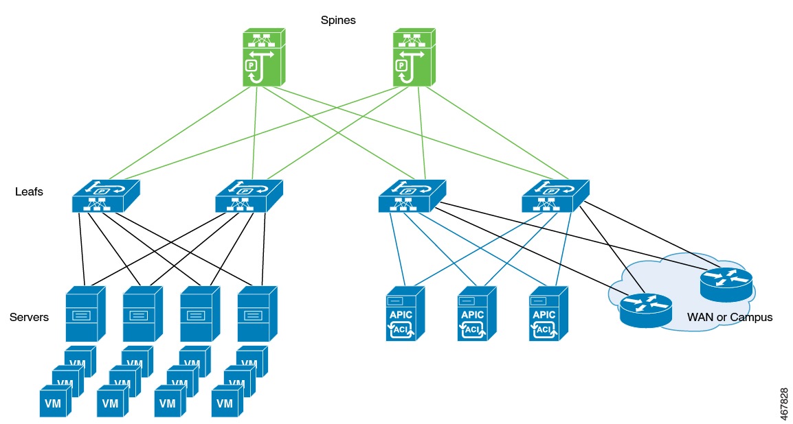
This diagram shows separate components that the ACI controller connects in a spine-and-leaf topology and manages as a single infrastructure fabric.

Figure 1. Cisco ACI Network Deployment
Diagram that illustrates a Cisco ACI network deployment with spine-and-leaf components managed by an ACI controller.

Example: Avoid interleaving traffic in ACI deployments

In a high-availability data center, Cisco ACI controllers integrate multiple workloads over a unified spine-and-leaf fabric. To maximize service continuity and avoid traffic conflicts during failover, the organization accelerates the shutdown of wireless management interfaces when it detects failure.

It also disables fast switchover notifications to manage the timing of the switchover, tunes the keepalive timeout, and uses GARP burst mitigation to prevent ARP instability. These combined mechanisms ensure seamless and reliable control plane transitions.


Methods to prevent interleaving traffic during controller switchover

To ensure a seamless controller switchover in ACI deployments and prevent disruptions for access points (APs) and clients, avoid interleaving traffic—that is, traffic originating from both the old and new active controllers at the same time. The following methods help eliminate management IP conflicts and ARP table instability during these events.

Bring down the wireless management interface faster

When a switchover occurs, APs and clients may disconnect if both controllers send traffic simultaneously. To prevent this, bring down the wireless management interface on the old active controller as soon as a failure is detected. This stops outgoing traffic from the previous controller and prevents management IP conflicts within the network. The standby controller then assumes the active role with a new IP–MAC binding.

The IP Data-Plane Learning feature in ACI tracks duplicate MAC addresses for the same IP address. It can trigger alarms and block affected IP addresses for a configurable period as a protective measure. When a failure is detected, the controller assigns the “non-participant” property to the affected chassis. The Data-Plane Learning feature monitors this status and quickly brings down the old management interface while blocking unwanted traffic, eliminating conflicts between old and new controllers.

Disable fast switchover notification

This mechanism provides more control during failover events. Normally, when a failure is detected, the active controller sends an explicit notification to the standby controller, enabling it to take over immediately. If you disable the fast switchover notification, the active controller no longer sends this alert. The standby controller instead detects the failure based solely on the keepalive timeout.

This configuration lets you control when traffic from the new active controller begins during a failure scenario. Adjusting the keepalive timeout allows you to match your operational needs. However, switchover will wait for the timeout to expire, which introduces a delay. This delay reduces the chance of overlapping traffic and minimizes the risk that both old and new controllers send management traffic at the same time.

GARP burst mitigation

During a controller switchover, a burst of Gratuitous ARP (GARP) traffic may occur. This burst can overwhelm ARP learning in ACI and destabilize ARP tables. To prevent this, the system retransmits GARP packets at a lower rate after the switchover. Lowering the GARP packet rate prevents excessive ARP table churn and supports smoother and more reliable controller transitions.


Best practices for deploying the ACI network in the controller

Check the maximum supported clients in High Availability to ensure that Cisco ACI does not exceed the configured IPv4 and IPv6 end points.


Disable the fast switchover notification mechanism (CLI)

Use these instructions to disable the fast switchover notification mechanism on your network device using CLI. Disabling this feature stops your device from sending explicit fast switchover notifications, which may help in some operational scenarios.

Procedure

1.

Enter global configuration mode.

Example:

Device# configure terminal
2.

Disable explicit fast switchover notification.

Example:

Device(config)# no redun-management fast-switchover
Note

Configure the fast switchover notification mechanism only on the primary controller. You do not need to configure it on the secondary controller.

3.

Return to privileged EXEC mode.

Example:

Device(config)# end

After you complete this procedure, your device no longer sends explicit notifications for fast switchover events. Make configuration changes only on the primary controller. You do not need to make changes on the secondary controller.


Configure the gratuitous ARP (GARP) retransmit (CLI)

Set the rate and interval for sending gratuitous ARP (GARP) packets to enhance network redundancy and update address tables.

Procedure

1.

Enter global configuration mode.

Example:

Device# configure terminal
2.

Determine the rate at which the GARP resend performs.

Example:

Device(config)# redun-management garp-retransmit burst packet-burst-size interval time-interval
Note
  • packet-burst-size : The valid range is from 0 to 1000. The value 0 refers to the disabled retransmit.

  • time-interval : Refers to the time interval, in seconds. The valid range is from 0 to 5 seconds. The value 0 refers to the disabled retransmit.

3.

Return to privileged EXEC mode.

Example:

Device(config)# end

The GARP retransmit settings are updated for the device.


Disable the initial GARP (CLI)

Disable the initial GARP retransmit mechanism in redundancy management to optimize ARP traffic and prevent unnecessary broadcasts.

Procedure

1.

Enter global configuration mode.

Example:

Device# configure terminal
2.

Disable the initial GARP.

Example:

Device(config)# no redun-management garp-retransmit initial
3.

Return to privileged EXEC mode.

Example:

Device(config)# end

The device will no longer send initial gratuitous ARP messages during redundancy failover, helping to minimize broadcast traffic in your network.


Configure a switchover

Enable manual failover to the standby unit and verify that high availability and redundancy work as expected.

Procedure

Force a failover to the standby unit by entering this command:

Example:

Device#redundancy force-switchover

After you enter this command, the standby controller takes the active role. The active controller reloads and becomes the standby controller. Use this command to test high availability cluster stability and confirm that switchovers work as expected.

Note

Use only the recommended command to test switchovers between Cisco Catalyst 9800 series wireless controllers. Using other commands, such as reload slot X (where X is the active controller), might cause unexpected behavior.

Note

In a scaled environment, avoid performing an immediate switchover after modifying WLAN or policy profile configurations. Doing so might cause unexpected behavior.

The system completes the switchover. The standby controller becomes active, and the previous active controller reloads to become standby. The switchover verifies high availability cluster stability.