Cisco Security Cloud Control: Secure Firewall ASA Management

PDF

Cisco Security Cloud Control: Secure Firewall ASA Management

Site-to-Site VPN configuration for FDM-Managed

Want to summarize with AI?

Log in

Learn how to create and manage site-to-site VPN tunnels between FDM-managed devices or extranet peers in Security Cloud Control.


Security Cloud Control supports these aspects of site-to-site VPN functionality on FDM-managed devices:

  • Both IPsec IKEv1 & IKEv2 protocols are supported.

  • Automatic or manual pre-shared keys for authentication.

  • IPv4 and IPv6. All combinations of inside and outside are supported.

  • IPsec IKEv2 site-to-site VPN topologies provide configuration settings to comply with Security Certifications.

  • Static and dynamic interfaces.

  • Support for the dynamic IP address for the extranet device as an endpoint.

Configure Site-to-Site VPN Connections with Dynamically Addressed Peers

Security Cloud Control allows you to create a site-to-site VPN connection between peers when one of the peers' VPN interface IP address is not known or when the interface obtains its address from a DHCP server. Any dynamic peer whose preshared key, IKE settings, and IPsec configurations match with another peer can establish a site-to-site VPN connection.

Consider two peers, A and B. The static peer is a device whose IP address of its VPN interface is fixed and a dynamic peer is a device whose IP address of the VPN interface is not known or has a temporary IP address.

The following use cases describe different scenarios for establishing a secure site-to-site VPN connection with dynamically-addressed peers:

  • A is a static peer, and B is a dynamic peer or conversely.

  • A is a static peer, and B is a dynamic peer with a resolved IP address from the DHCP server or conversely. You can select Bind VPN to the assigned IP to establish the VPN connection between the IP address of the static peer and the DHCP assigned IP address of the dynamic peer.

  • A and B are dynamic with resolved IP addresses from the DHCP server. In such a case, you must select Bind VPN to the assigned IP for at least one peer to establish the VPN connection between the IP address of the static peer and the DHCP assigned IP address of the dynamic peer.

  • A is a dynamic peer, and B is an extranet device with a static or dynamic IP address.

  • A is a dynamic peer with a resolved IP address from the DHCP server, and B is an Extranet device with a static or dynamic IP address. You can select Bind VPN to the assigned IP to establish the VPN connection between the IP address of the static peer and the DHCP assigned IP address of the dynamic peer.

If you select Bind VPN to the assigned IP, the VPN binds statically to the DHCP assigned IP address. However, this dynamic interface can receive many new IP addresses after the peer restarts. Although the VPN tunnel updates the new IP address, the other peer is not updated with the new configuration. You must deploy the site-to-site configuration again for out-of-band changes on the other peer.

Note

If the IP address of the interface is changed by using a local manager like Firewall Device Manager, the Configuration Status of that peer in Security Cloud Control shows "Conflict Detected". When you resolve this out-of-band change, the Configuration Status of the other peer changes to the "Not Synced" state. You must deploy the Security Cloud Control configuration to the device which is in "Not Synced" state.

Typically, the dynamic peer must be the one that initiates the connection as the other peer would not know the IP address of the dynamic peer. When the remote peer attempts to establish the connection, the other peer validates the connection using the preshared key, IKE settings, and IPsec configurations.

Because the VPN connection is established only after the remote peer initiates the connection, any outbound traffic that matches access control rules that allow traffic in the VPN tunnel will be dropped until that connection is established. This ensures that data does not leave your network without the appropriate encryption and VPN protection.

Note

A site-to-site VPN connection cannot be configured in the following scenarios:

  • If both peers have DHCP assigned IP addresses.

    • Workaround: You can configure a site-to-site VPN, if one of the peers has a resolved IP address from the DHCP server. In such a case, you must select Bind VPN to the assigned IP to configure site-to-site VPN.

  • If a device has more than one dynamic peer connection.

    • Workaround: You can configure a site-to-site VPN by performing the following steps:

      • Consider three devices A, B, and C.

      • Configure site-to-site VPN connection between A (static peer) and B (dynamic peer).

      • Configure site-to-site VPN connection between A and C (dynamic peer) by creating an Extranet device. Assign the static VPN interface IP address of A to the Extranet device and establish a connection with C.

FDM-Managed Device Site-to-Site VPN Guidelines and Limitations

  • Security Cloud Control does not support a crypto-acl to design the interesting traffic for S2S VPN. It only supports protected networks.

  • Security Cloud Control does not currently support the management, monitoring, or use of Virtual Tunnel Interface (VTI) tunnels on ASA or FDM-managed devices. Devices with configured VTI tunnels can be onboarded to Security Cloud Control but it ignores the VTI interfaces. If a security zone or static route references a VTI, Security Cloud Control reads the security zone and static route without the VTI reference. Security Cloud Control support for VTI tunnels is coming soon.

  • Whenever IKE ports 500/4500 are in use or when there are some PAT translations that are active, the site-to-site VPN cannot be configured on the same ports as it fails to start the service on those ports.

  • Transport mode is not supported only tunnel mode. IPsec tunnel mode encrypts the entire original IP datagram which becomes the payload in a new IP packet. Use tunnel mode when the firewall is protecting traffic to and from hosts positioned behind a firewall. Tunnel mode is the normal way regular IPsec is implemented between two firewalls (or other security gateways) that are connected over an untrusted network, such as the Internet.

  • For this release, only PTP topology is supported, containing one or more VPN tunnels. Point-to-point (PTP) deployments establish a VPN tunnel between two endpoints.


Create a Site-To-Site VPN Tunnel Between FDM-managed Devices

Note that an FDM-managed device has the capability to establish a secure VPN tunnel either with another FDM-managed device or with an extranet device.

Procedure

1.

From the Security Cloud Control Home page, click Firewall.

2.

In the left pane, choose Secure Connections > Network Connections > Site to Site VPN.

3.

Click the Create Tunnel () icon and then click Site-to-Site VPN.

4.

In the Peer Selection area, provide the following information:

  • Configuration Name: Enter a unique topology name.

    We recommend naming your topology to indicate that it is an FDM-managed device VPN, and its topology type.

  • Peer 1: Click the FDM tab and select an FDM-managed device.

  • Peer 2: Click the FDM tab and select an FDM-managed device.

    If you choose an extranet device, select Static and specify an IP address or select Dynamic for extranet devices with DHCP assigned IP. The IP Address displays the IP address for static interface or DHCP Assigned for the dynamic interface.

    Note

    If one or both endpoint devices have dynamic IP addresses, see Configure Site-to-Site VPN Connections with Dynamically-Addressed Peers for additional instructions.

5.

Click Next.

6.

In the Peer Details area, provide the following information:

  • VPN Access Interface: Select the interface to establish a connection between peer 1 and peer 2.

  • Routing: Click Add Networks and select one or more protected networks to establish a site-to-site tunnel between the protected networks of peer 1 and peer 2

  • (Optional) NAT Exempt Interface: Select NAT Exempt for peer 1 and peer 2 to exempt the VPN traffic from NAT policies on the local VPN access interface. It must be configured manually for individual peers. If you do not want NAT rules to apply to the local network, select the interface that hosts the local network. This option works only if the local network resides behind a single routed interface (not a bridge group member). If the local network is behind more than one routed interface or one or more bridge group members, you must manually create the NAT exempt rules.

7.

Click Next.

8.

In the IKE Settings area, choose the IKE versions to use during Internet Key Exchange (IKE) negotiations and specify the privacy configurations: For more information on the IKE policies, see Configuring the Global IKE Policy.

Note

IKE policies are global to a device and apply to all VPN tunnels associated with it. Therefore, adding or deleting policies affect all VPN tunnels in which this device is participating.

  1. Select either or both options as appropriate.

    Note

    By default, IKEV Version 2 is enabled.

  2. Click Add IKEv2 Policies to select the IKEv2 policies for peer 1 and peer 2.

  3. The Local Pre-Shared Key and Remote Pre-Shared Key for the participating devices are auto-genreated. Preshared keys are secret key strings configured on each peer in the connection. These keys are used by IKE during the authentication phase.

  4. Click IKE Version 1 to enable it.

  5. Click Add IKEv1 Policies to select the IKEv1 policies for peer 1 and peer 2.

  6. The IPEv1 Pre-Shared Key is auto-generated.

9.

Click Next.

10.

In the IPSec Settings area, specify the IPSec configurations for peer 1 and peer 2. The corresponding IKEV proposals are available depending on the selection that is made in the IKE Settings step.

For more information on the IPSec settings, see the IPsec proposal and IKE policy objects.

  1. Click Add IKEv2 IPSec Proposals and select the IKEv2 proposals you want for peer 1 and peer 2.

  2. Choose the Diffie-Hellman Group for Perfect Forward Secrecy. For more information, see Deciding Which Diffie-Hellman Modulus Group to Use.

  3. Click Next.

11.

In the Finish area, you will find a summary of the configurations you have completed.

Read the configuration and then click Submit if you're satisfied.


Configure Networking for Protected Traffic Between the Site-To-Site Peers

After completing the configuring of the Site-To-Site connection, make sure that you perform the following configuration for VPN to function on all targeted devices.

Procedure

1.

Configure AC policies:

Configure AC policies for permitting bidirectional traffic between the protected networks behind both peers. These policies help the packets to traverse to the intended destination without being dropped.

Note

You must create AC policies for incoming and outgoing traffic on both peers.

  1. In the Security Cloud Control navigation bar at the left, click Policies and select the option that you want.

  2. Create policies for incoming and outgoing traffic on both peers.

    The following example shows steps for creating AC policies on both peers.

    Consider two FDM-managed devices 'FTD_BGL_972' and 'FTD_BGL_973' with Site-To-Site VPN connection between two protected networks 'boulder-network' and 'sanjose-network' respectively.

    Creating the AC policy for permitting incoming traffic:

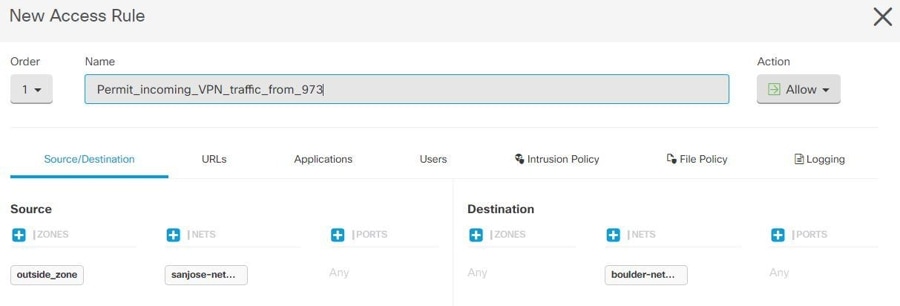
    The policy 'Permit_incoming_VPN_traffic_from_973' is created on the 'FTD_BGL_972' device for allowing incoming traffic from the peer ('FTD_BGL_973').

    • Source Zone: Set the zone of the peer device from which the network traffic originates. In this example, the traffic is originating from FTD_BGL_973 and reaching FTD_BGL_972.

    • Source Network: Set the protected network of the peer device from which the network traffic originates. In this example, traffic is originating from 'sanjose-network' which is the protected network behind the peer device (FTD_BGL_973).

    • Destination Network: Set the protected network of the device on which the network traffic arrives. In this example, traffic is arriving at 'boulder-network' which is the protected network behind the peer device (FTD_BGL_972). Note: The remaining fields can have the default value ("Any").

    • Set Action to Allow for allowing the traffic subject to the intrusion and other inspection settings in the policy.

    Creating the AC policy for permitting outgoing traffic:

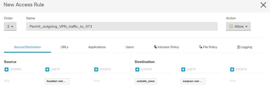
    The policy 'Permit_outgoing_VPN_traffic_to_973' is created on the 'FTD_BGL_972' device for permitting outgoing traffic to the peer ('FTD_BGL_973').

    • Source Network: Set the protected network of the peer device from which the network traffic originates. In this example, traffic is originating from 'boulder-network' which is the protected network behind the peer device (FTD_BGL_972).

    • Destination Zone: Set the zone of the peer device on which the network traffic arrives. In this example, the traffic is arriving from FTD_BGL_972 and reaching FTD_BGL_973.

    • Destination Network: Set the protected network of the peer on which the network traffic arrives. In this example, traffic is arriving on 'sanjose-network' which is the protected network behind the peer device (FTD_BGL_972). Note: The remaining fields can have the default value ("Any").

    • Set Action to Allow for allowing the traffic subject to the intrusion and other inspection settings in the policy.

After creating AC policies on one device, you must create similar policies on its peer.

2.

If NAT is configured on either of the peer devices, you need to configure the NAT exempt rules manually. See Exempting Site-to-Site VPN Traffic from NAT.

3.

Configure routing for receiving the return VPN traffic on each peer.

For more information, see Configure Routing.

  1. Gateway-Select the network object that identifies the IP address for the gateway to the destination network. Traffic is sent to this address.

  2. Interface-Select the interface through which you want to send traffic. In this example, the traffic is sent through 'outside' interface.

  3. Destination Networks-Select one or network objects, that identify the destination network. In this example, the destination is 'sanjose-network' which is behind peer (FTD_BGL_973).

After configuring routing settings on one device, you must configure similar settings on its peer.


Edit an Existing Security Cloud Control Site-To-Site VPN

The advanced configuration wizard is used by default to modify an existing site-to-site VPN configuration.

Procedure

1.

From the Security Cloud Control Home page, click Firewall.

2.

In the left pane, choose Secure Connections > Network Connections > Site to Site VPN.

3.

Select the desired site-to-site VPN tunnel that you want to edit.

4.

In the Actions pane, click Edit.

Note

Alternatively, you can perform the following to edit the configuration:

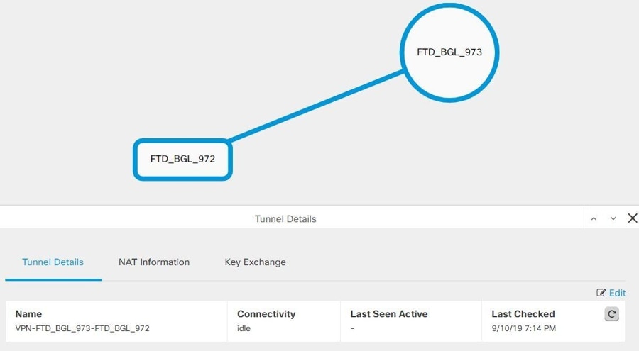
  1. Open the VPN page and click Global View button in the filter panel (for more information, see Global View).

    The illustration of all site-to-site VPN tunnels available across all devices appears.

    To edit the configuration, one of the peers must be FDM-managed device.

  2. Select a device by clicking the box.

  3. Click View details to view its peers.

  4. Click the peer device to view the tunnel details.

    You can view the tunnel details, NAT information, and key exchange information pertaining to the device.

  5. Click Edit in Tunnel Details.

5.

In the Peer Devices section, you can modify the following device configurations: Configuration Name, VPN Access Interface, and Protected Networks.

Note

You cannot change the participating devices.

6.

In the IKE Settings section, you can modify the following IKEv2 policies configurations:

  1. Click the blue plus button for the respective device and select new IKEv2 policies. To delete an existing IKEv2 Policy, hover-over the selected policy and click the x icon.

  2. Modify the Pre-Shared Key for the participating devices. If the pre-shared keys are different for endpoint devices, click the blue settings button and enter the appropriate pre-shared keys for the devices.
  3. Click Next.

7.

In the IPSec Settings section, you can modify the following IPSec configurations:

  1. Click the blue plus button to select new IKEv2 proposals. To delete an existing IKEv2 Proposal, hover-over the selected proposal and click the x icon.

  2. Choose the Diffie-Hellman Group for Perfect Forward Secrecy.

  3. Click Edit VPN, and then Finish.

The Point to point VPN is modified and updated with all the changes you have made.


Delete a Security Cloud Control Firewall Management Site-To-Site VPN Tunnel

Procedure

1.

From the Security Cloud Control Home page, click Firewall.

2.

In the left pane, click Secure Connections > Network Connections > Site to Site VPN to open the VPN page.

3.

Select the desired site-to-site VPN tunnel that you want to delete.

4.

In the Actions pane on the right, click Delete.

The selected site-to-site VPN tunnel is deleted.


Exempt Site-to-Site VPN Traffic from NAT

When you have a site-to-site VPN connection defined on an interface, and you also have NAT rules for that interface, you can optionally exempt the traffic on the VPN from the NAT rules. You might want to do this if the remote end of the VPN connection can handle your internal addresses.

When you create the VPN connection, you can select the NAT Exempt option to create the rules automatically. However, this works only if your local protected network is connected through a single routed interface (not a bridge group member). If instead, the local networks in the connection reside behind two or more routed interfaces or one or more bridge group members, you need to configure the NAT exempt rules manually.

To exempt VPN traffic from NAT rules, you create an identity manual NAT rule for the local traffic when the destination is the remote network. Then, apply NAT to the traffic when the destination is anything else (for example, the Internet). If you have more than one interface for the local network, create rules for each interface. Also, consider the following suggestions:

  • If there is more than one local network in the connection, create a network object group to hold the objects that define the networks.

  • If you are including both IPv4 and IPv6 networks in the VPN, create separate identity NAT rules for each.

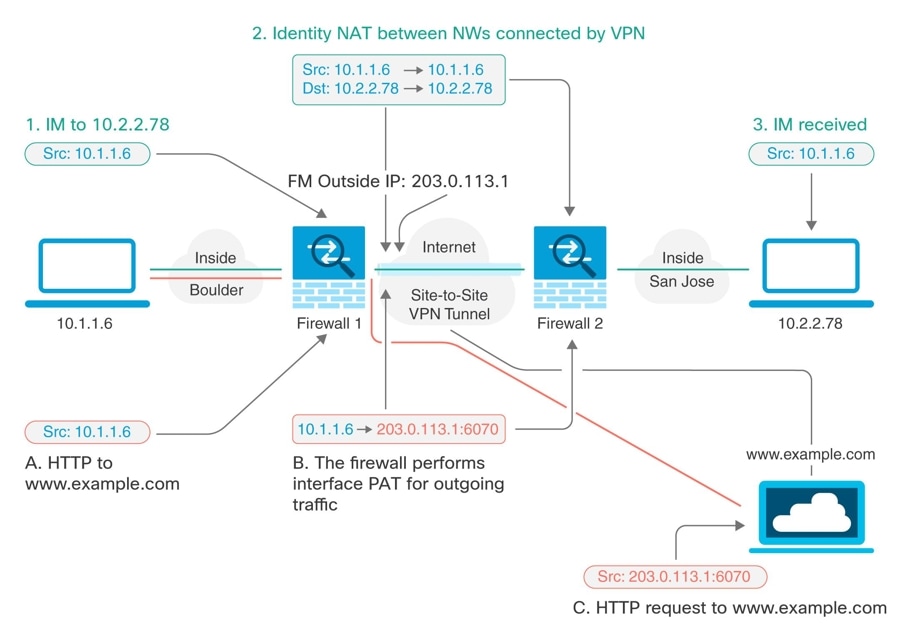
Consider the following example, which shows a site-to-site tunnel connecting the Boulder and San Jose offices. For traffic that you want to go to the Internet (for example from 10.1.1.6 in Boulder to www.example.com), you need a public IP address provided by NAT to access the Internet. The below example uses interface Port Address Translation (PAT) rules. However, for traffic that you want to go over the VPN tunnel (for example from 10.1.1.6 in Boulder to 10.2.2.78 in San Jose), you do not want to perform NAT; you need to exempt that traffic by creating an identity NAT rule. Identity NAT translates an address to the same address.

The following example explains the configuration for Firewall1 (Boulder). The example assumes that the inside interface is a bridge group, so you need to write the rules for each member interface. The process is the same if you have a single or multiple routed inside interfaces.

Note

This example assumes IPv4 only. If the VPN also includes IPv6 networks, create parallel rules for IPv6. Note that you cannot implement IPv6 interface PAT, so you need to create a host object with a unique IPv6 address to use for PAT.

Procedure

1.

From the Security Cloud Control Home page, click Firewall.

2.

Create objects to define the various networks.

  1. In the left pane, click Objects.

  2. Click the blue plus button to create an object.

  3. Click ASA > Network.

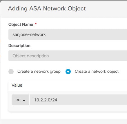
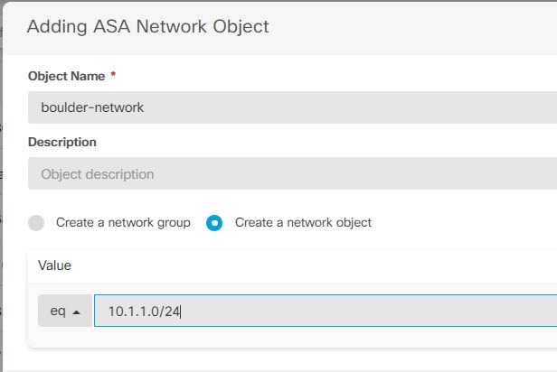
  4. Identify the Boulder inside network.

  5. Enter an object name (for example, boulder-network).

  6. Select Create a network object.

  7. In the Value section:

    • Select eq and enter a single IP address or a subnet address expressed in CIDR notation.

    • Select range and enter an IP address range. For example, enter the network address as 10.1.1.0/24.

  8. Click Add.

  9. Click the blue plus button to create an object.

  10. Define the inside San Jose network.

  11. Enter the object name (for example, san-jose).

  12. Select Create a network object.

  13. In the Value section:

    • Select eq and enter a single IP address or a subnet address expressed in CIDR notation.

    • Select range and enter an IP address range. For example, enter the network address as 10.1.1.0/24.

  14. Click Add.

3.

Configure manual identity NAT for the Boulder network when going over the VPN to San Jose on Firewall1 (Boulder).

  1. In the left pane, click Security Devices > All Devices.

  2. Use the filter to find the device for which you want to create the NAT rule.

  3. In the Management area of the details panel, click NAT .

  4. Click > Twice NAT.

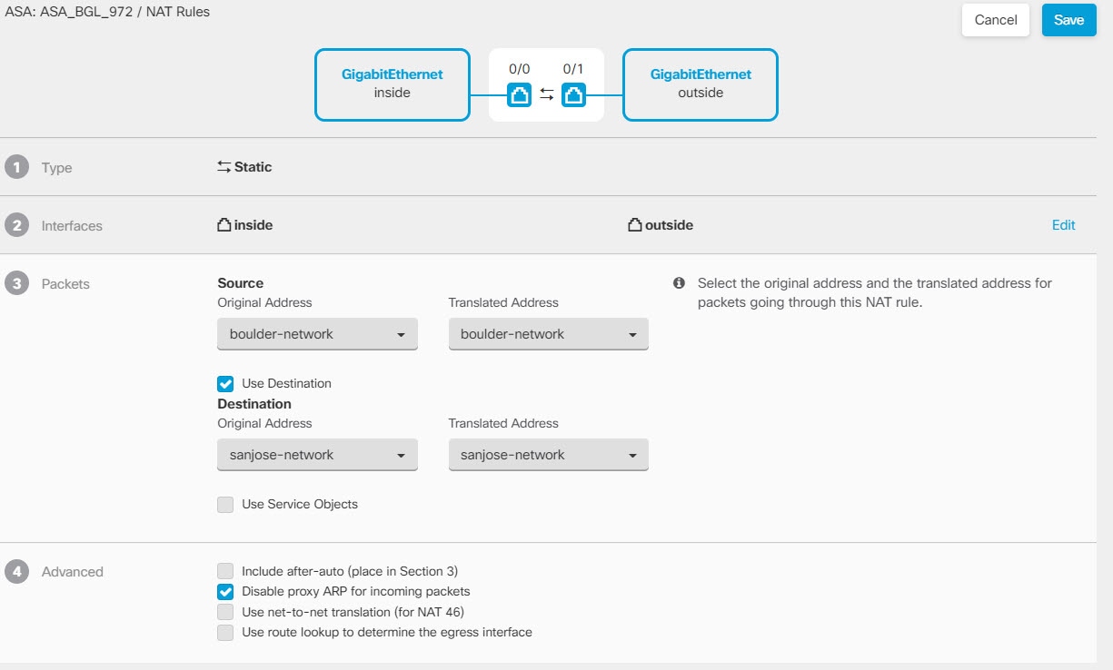
    • In section 1, select Static. Click Continue.

    • In section 2, select Source Interface = inside and Destination Interface = outside. Click Continue.

    • In section 3, select Source Original Address = 'boulder-network' and Source Translated Address = 'boulder-network'.

    • Select Use Destination.

    • Select Destination Original Address = 'sanjose-network' and Source Translated Address = 'sanjose-network'. Note: Because you do not want to translate the destination address, you need to configure identity NAT for it by specifying the same address for the original and translated destination addresses. Leave all of the port fields blank. This rule configures identity NAT for both source and destination.

    • Select Disable proxy ARP for incoming packets.

    • Click Save.

    • Repeat the process to create equivalent rules for each of the other inside interfaces.

4.

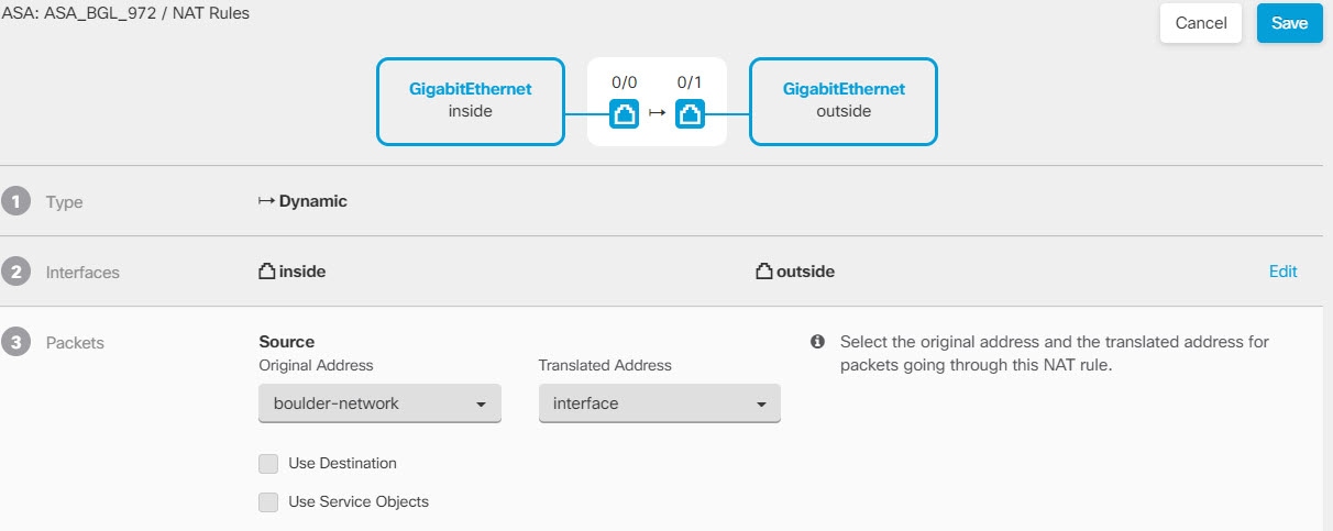
Configure manual dynamic interface PAT when going to the Internet for the inside Boulder network on Firewall1 (Boulder). Note: There might already be dynamic interface PAT rules for the inside interfaces, covering any IPv4 traffic, as these are created by default during initial configuration. However, the configuration is shown here for completeness. Before completing these steps, check whether a rule already exists that covers the inside interface and network, and skip this step if it does.

  1. Click > Twice NAT.

  2. In section 1, select Dynamic. Click Continue.

  3. In section 2, select Source Interface = inside and Destination Interface = outside. Click Continue.

  4. In section 3, select Source Original Address = 'boulder-network' and Source Translated Address = 'interface'.

  5. Click Save.

  6. Repeat the process to create equivalent rules for each of the other inside interfaces.

5.

Deploy configuration changes to Security Cloud Control. For more information, see Deploy configuration changes made using the Security Cloud Control GUI.

6.

If you are also managing Firewall2 (San Jose), you can configure similar rules for that device.

  • The manual identity NAT rule would be for 'sanjose-network' when the destination is boulder-network. Create new interface objects for the Firewall2 inside and outside networks.

  • The manual dynamic interface PAT rule would be for 'sanjose-network' when the destination is "any."


Configure Static and Default Routes for FDM-Managed Devices

Define static routes on an FDM-managed device so it knows where to send packets bound for networks not directly connected to the interfaces on the system.

Consider creating a default route. This is the route for network 0.0.0.0/0. This route defines where to send packets whose egress interface cannot be determined by existing NAT translations, static NAT rules, or other static routes.

You might need other static routes if the default gateway cannot be used to get to all networks. For example, the default route is usually an upstream router on the outside interface. If there are additional inside networks that are not directly connected to the device, and they cannot be accessed through the default gateway, you need static routes for each of those inside networks.

You cannot define static routes for the networks that are directly connected to system interfaces. The system automatically creates these routes.