Cisco Routed Optical Networking Solution Guide, Release 4.0

PDF

Implement phase

Want to summarize with AI?

Log in

Overview

This section explains the implementation activities required to deploy the sample Routed Optical Networking service. It covers hardware installation, base configuration, device onboarding, adapter setup, SSO, cross-launching, and multilayer service provisioning.

The implement phase involves:

  1. Installation of hardware components

    1. Hardware staging or installation and initial base configuration required for management connectivity.

    2. All onboard software updates must be completed to the required revision.

    3. All associated base wiring must be completed to support the network. This includes connections between the optical elements and connections between routers and optical add/drop end-points to support Routed Optical Networking circuits using ZR and ZR+ optics. See Deployment Topologies.

    4. Install Cisco Optical Site Manager to support NCS 1010 nodes. See Install Cisco Optical Site Manager

  2. Installation of automation software somponents

    1. Complete all server hardware installation and base configuration to support the solution, including VMWare ESX if not already installed.

    2. Install the following software components to support the Routed Optical Networking solution.

  3. Onboarding of devices

    1. Add devices to Cisco Optical Network Controller. See Onboard Devices to Cisco Optical Network Controller.

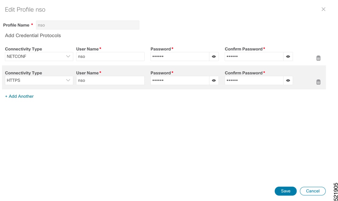
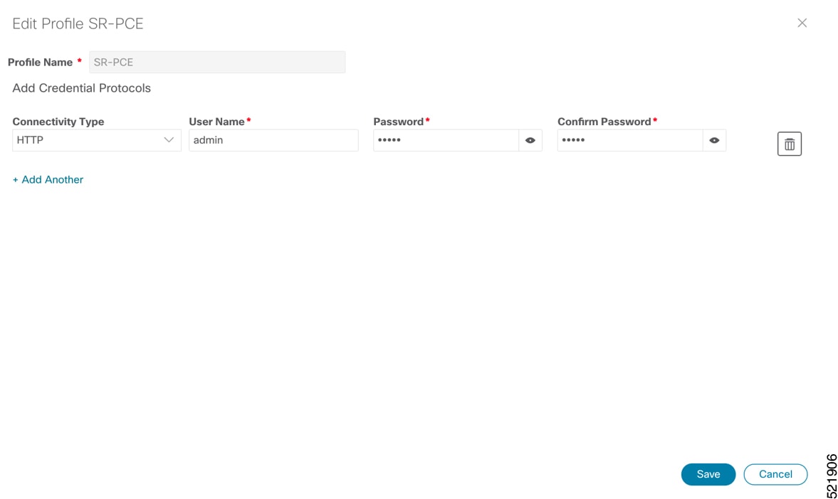
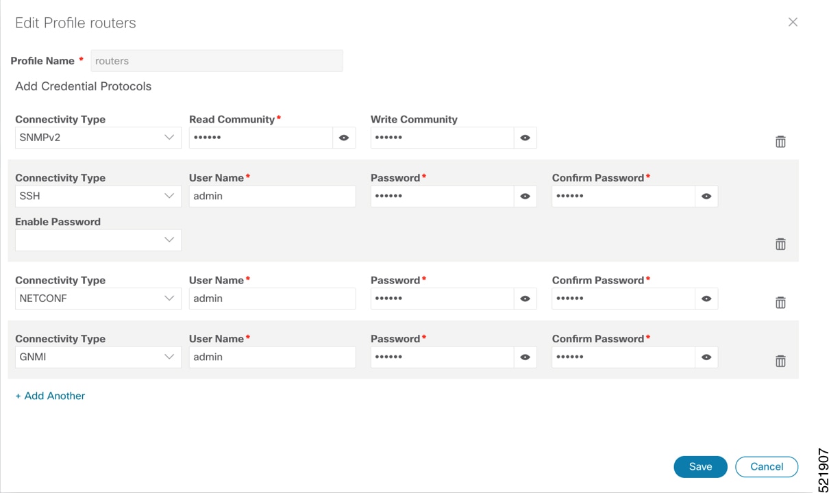
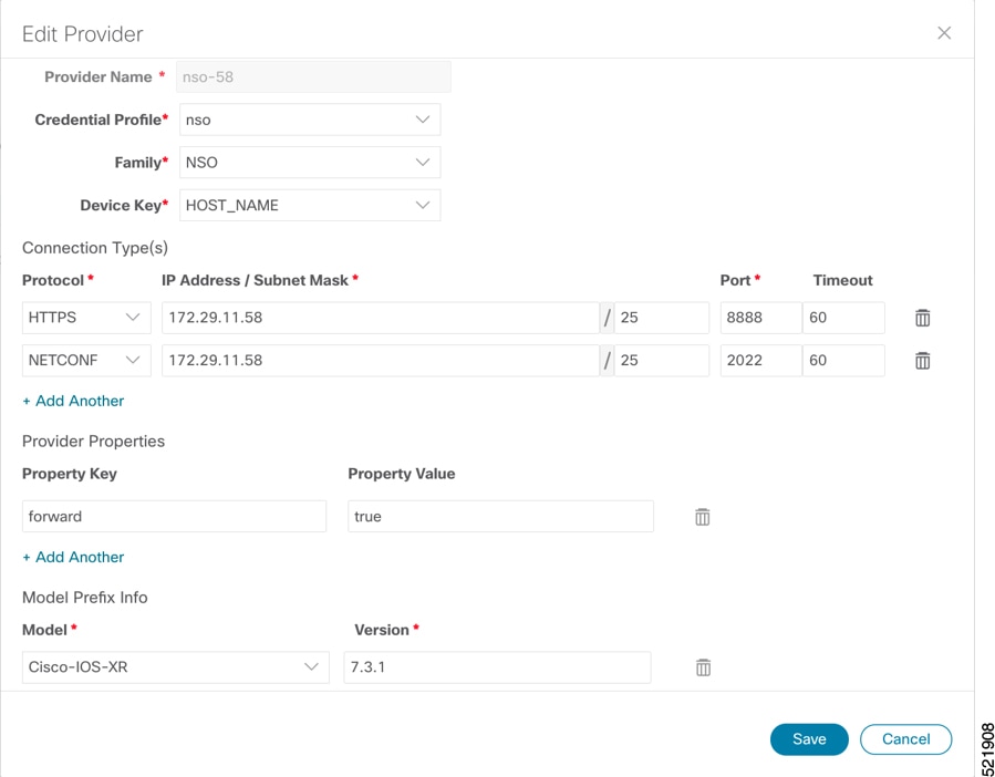
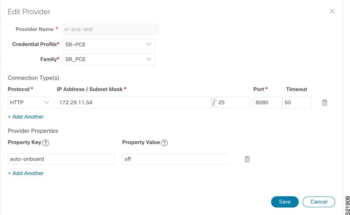
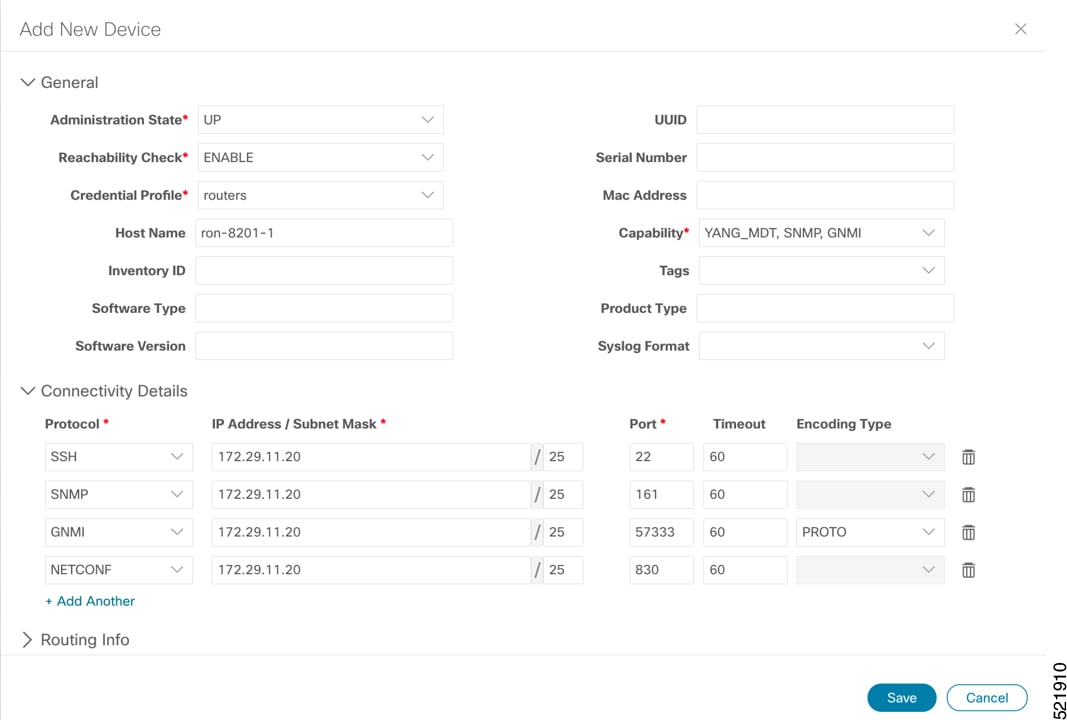
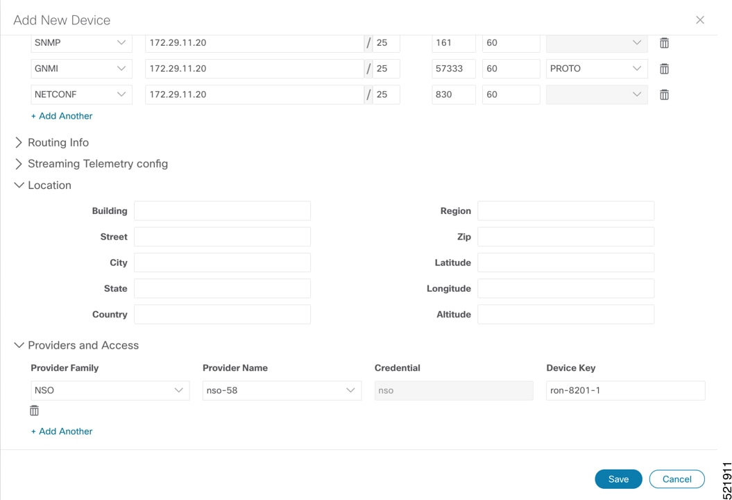
    2. Add NSO, SR-PCE, and devices to Crosswork Network Controller. See Add SR-PCE providers, NSO providers, and routers to Crosswork Network Controller.

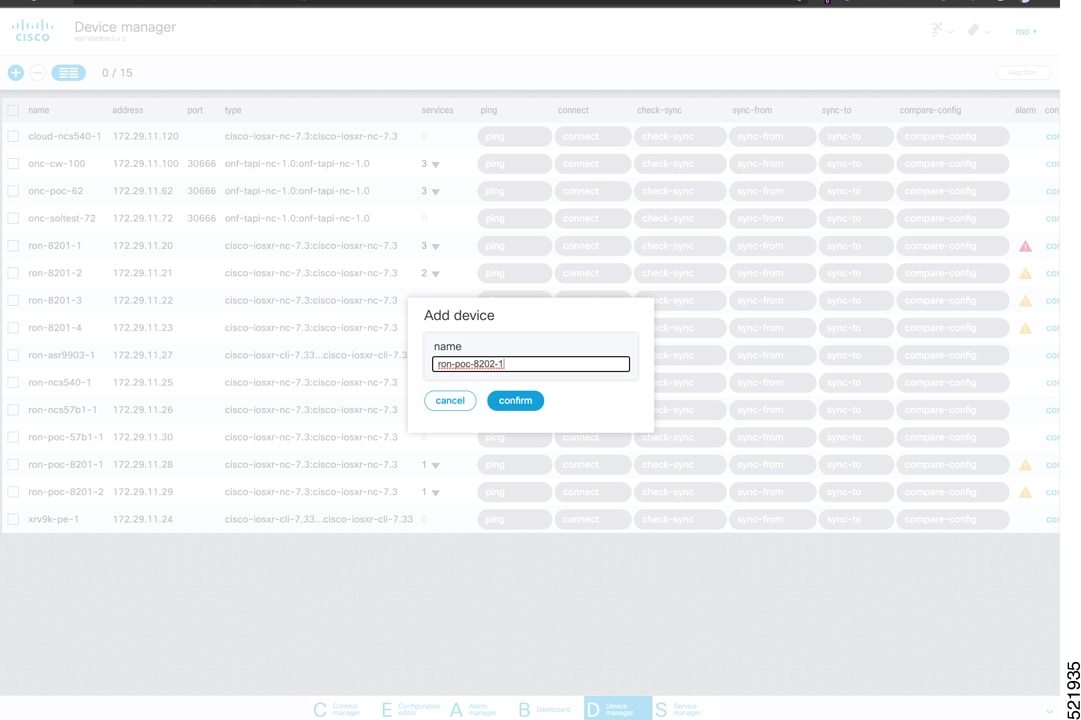
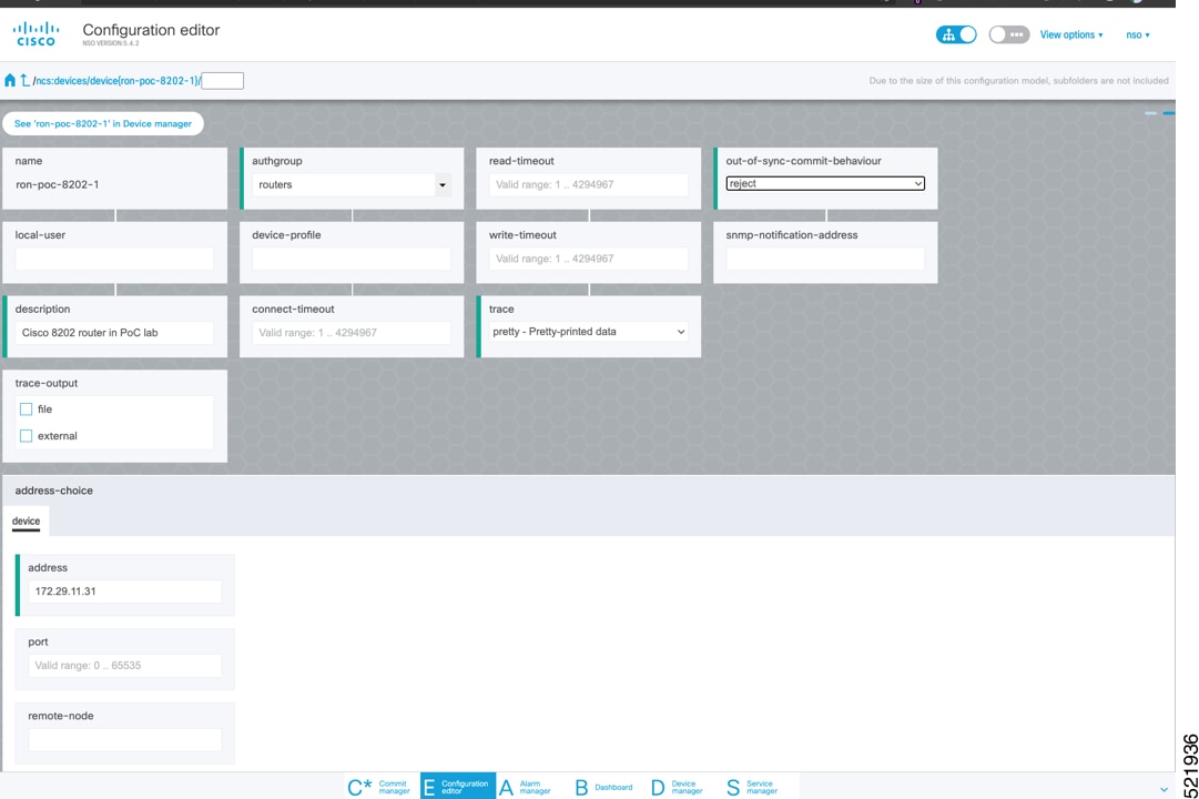
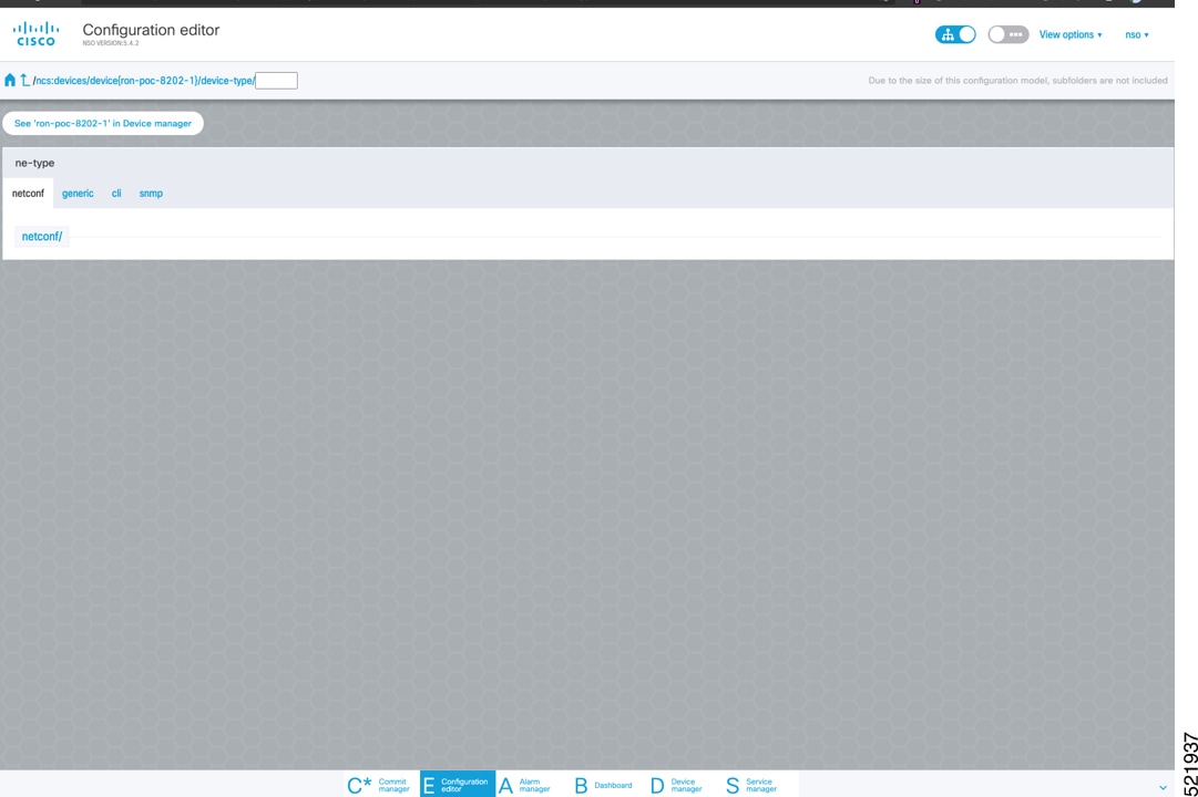
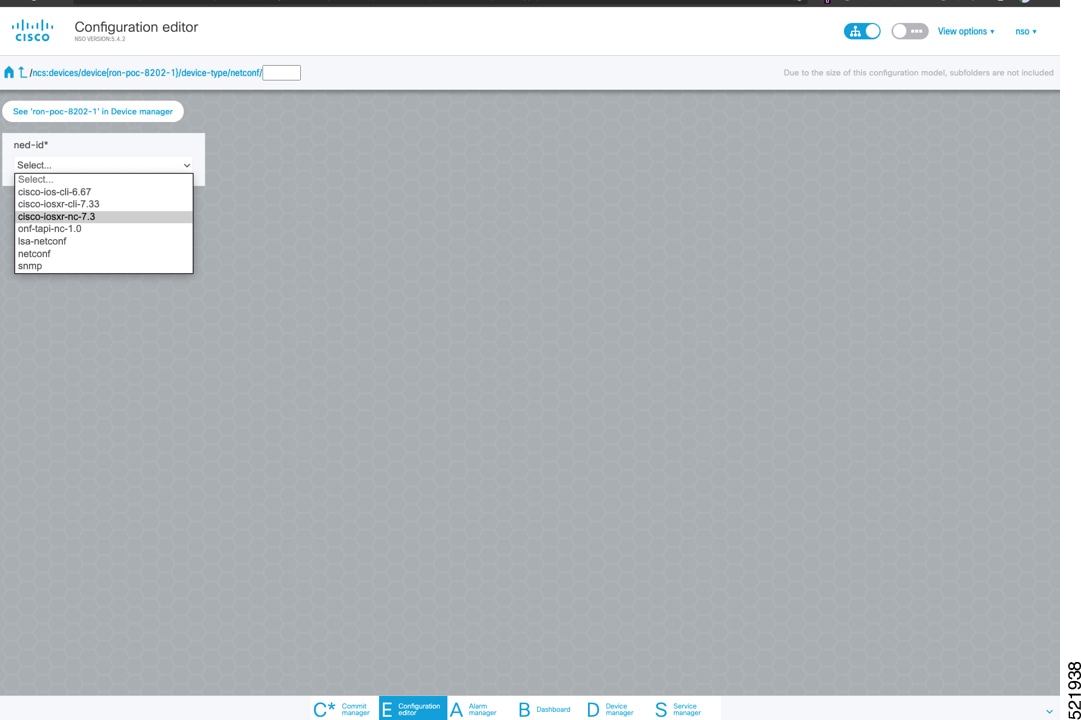
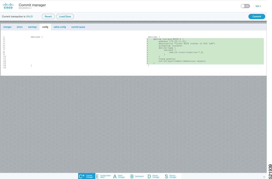
    3. Add routers to NSO using the IOS-XR CLI NED. See Step 3 in Provision an ML service using NSO Routed Optical Networking CFP.

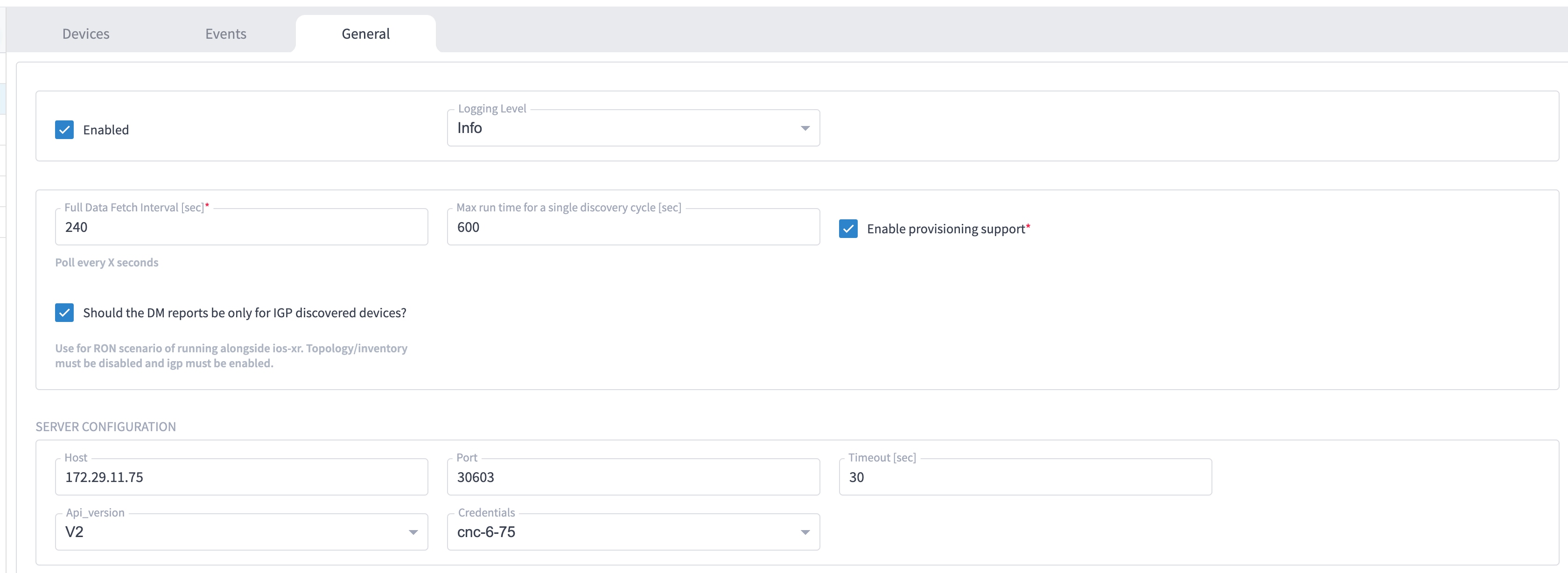
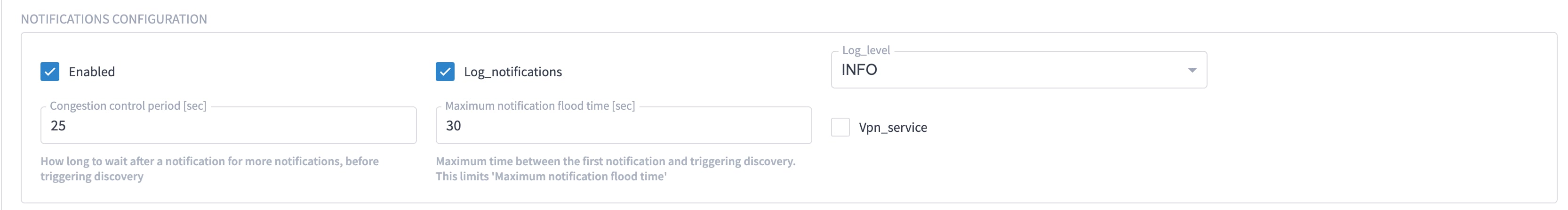
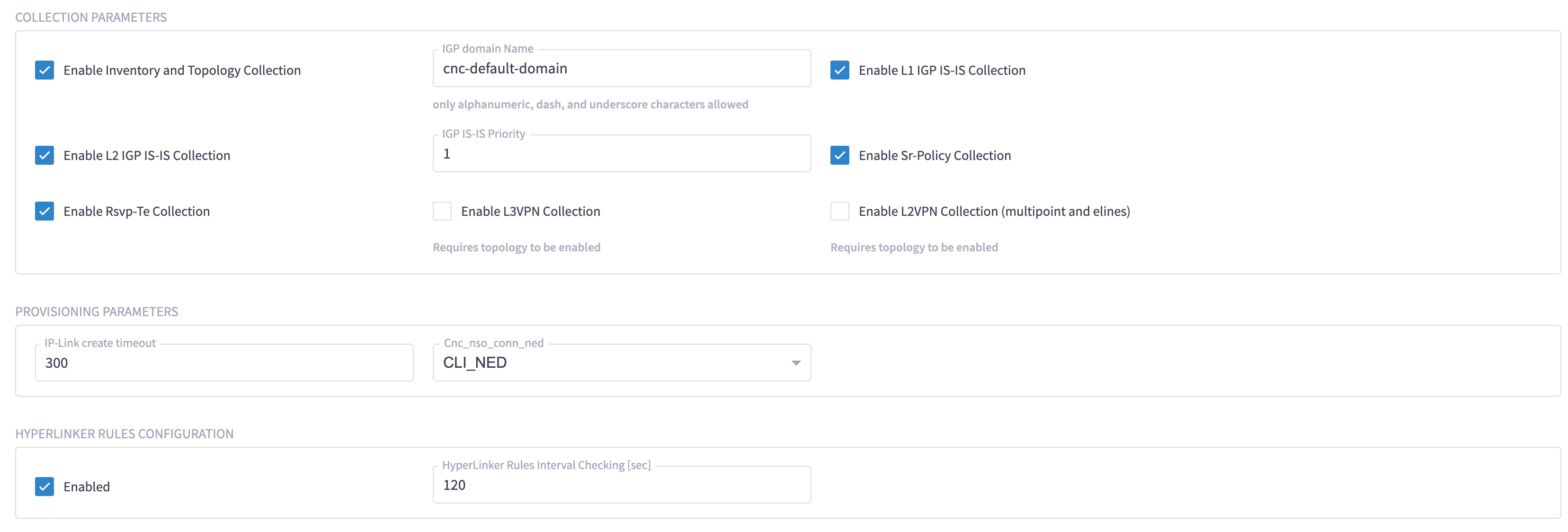
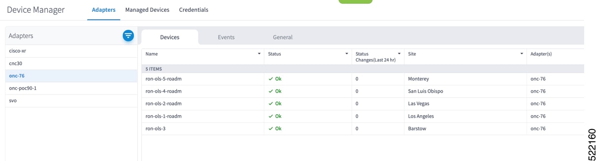
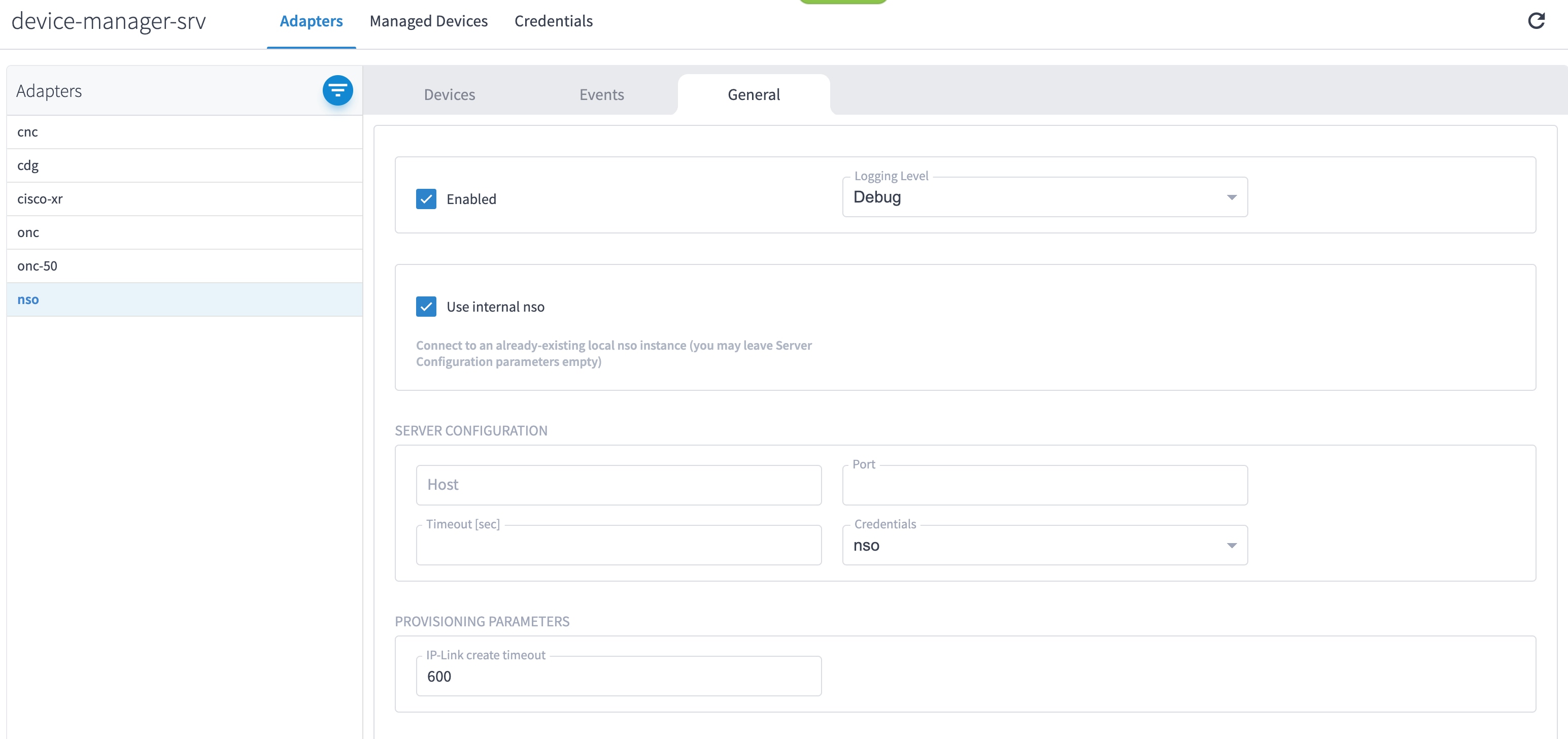
    4. Add and configure the following Crosswork Hierarchical Controller adapters. See Configure adapters for Routed Optical Networking in Crosswork Hierarchical Controller.

      Note

      This step is required only if the Routed Optical Networking ML service is provisioned via the Crosswork Hierarchical Controller GUI.

      • Add and configure the Crosswork Network Controller adapter.

      • Create or import sites in Crosswork Hierarchical Controller. See the sections, "Add Sites" and "Export and Import Sites" in the Cisco Crosswork Hierarchical Controller Administration Guide 8.0.

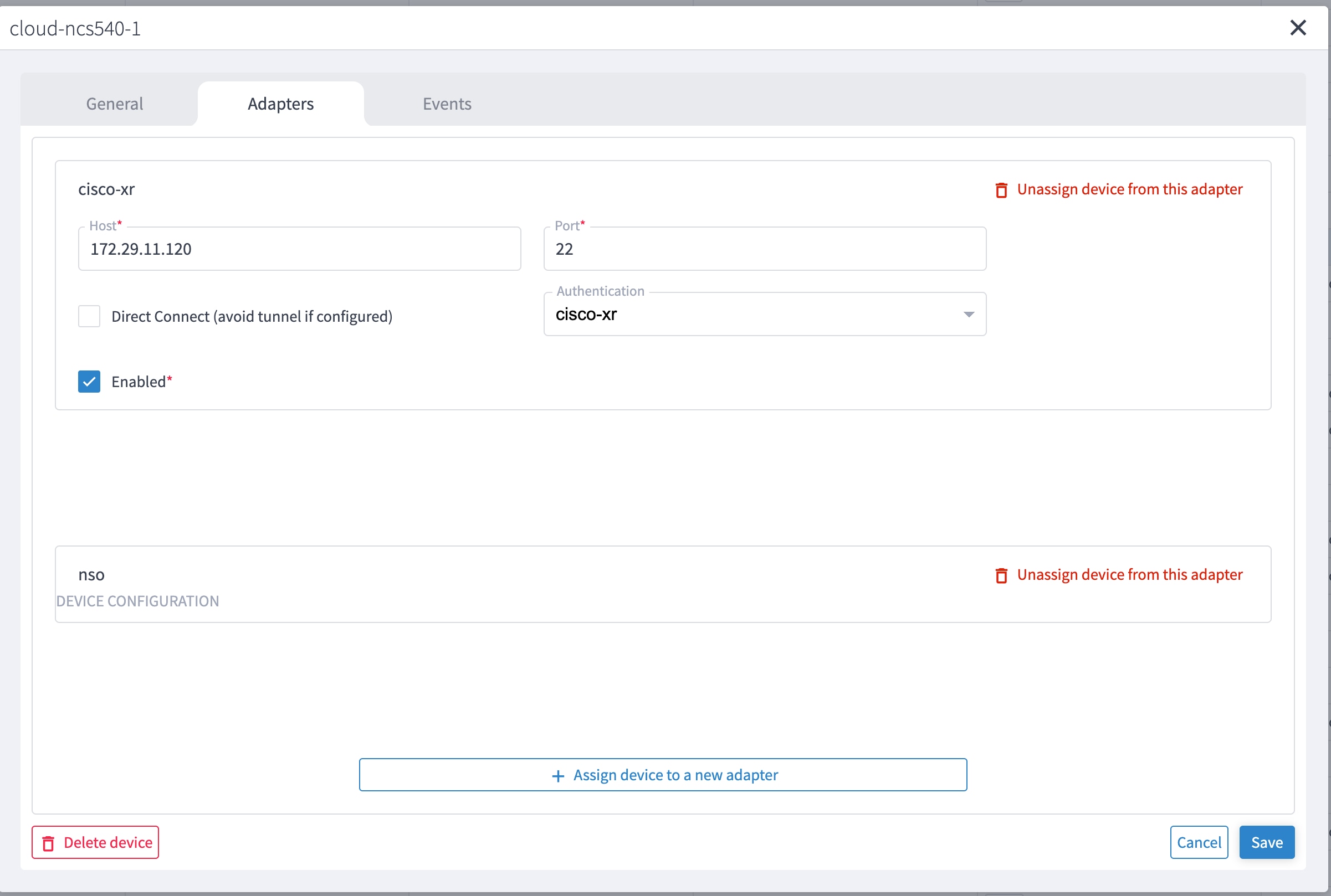
      • Add and configure the IOS-XR adapter. Create router devices in Crosswork Hierarchical Controller using the IOS-XR adapter type. After the routers are created, add the Crosswork Network Controller adapter to the router device.

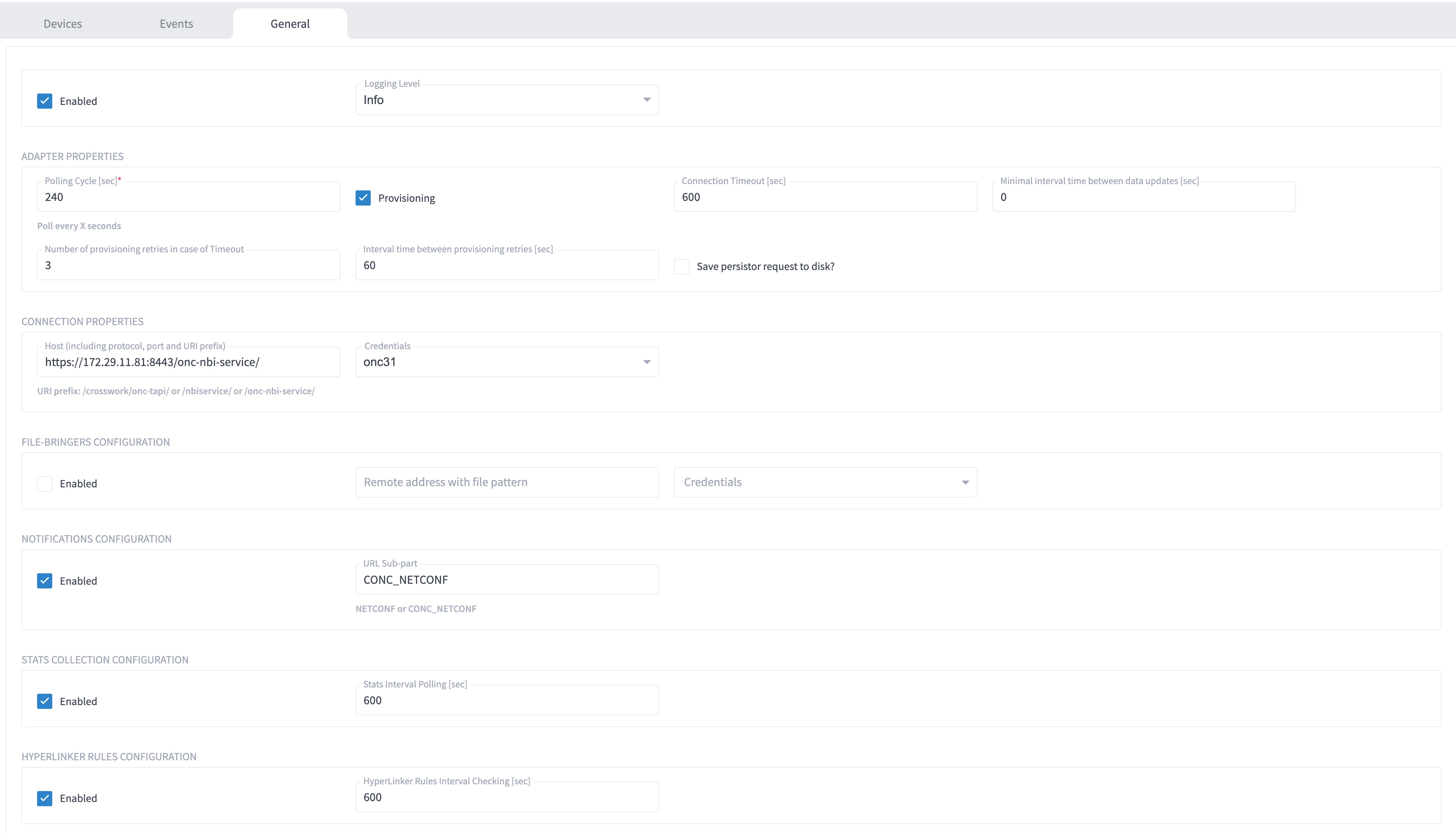
      • Add and configure the Cisco Optical Network Controller adapter.

  4. Provisioning of services

    1. Ensure all device interconnections are complete.

    2. To provision the Routed Optical Networking ML service, use either one of the procedures:

      1. Using the NSO GUI:

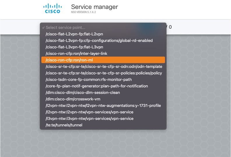
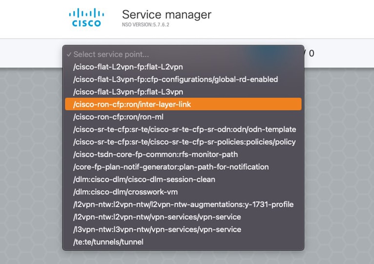
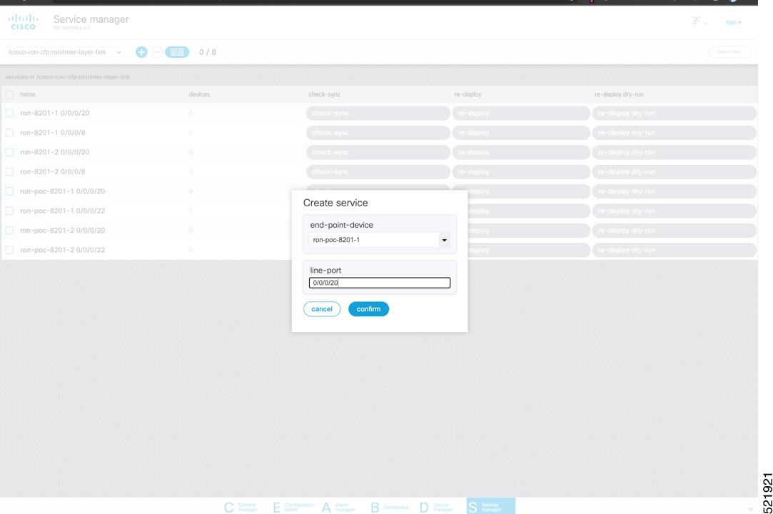
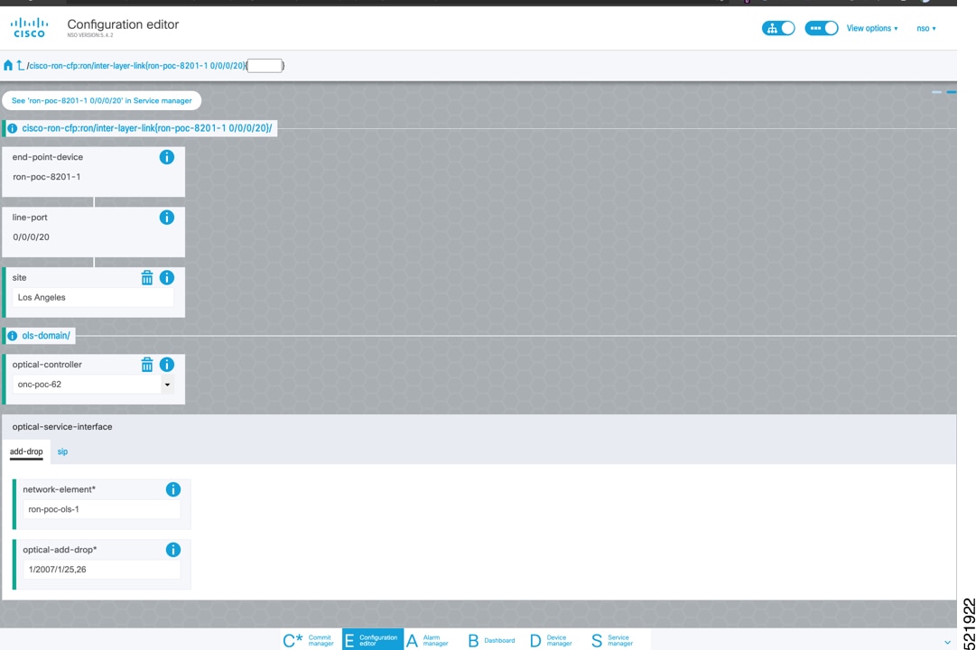
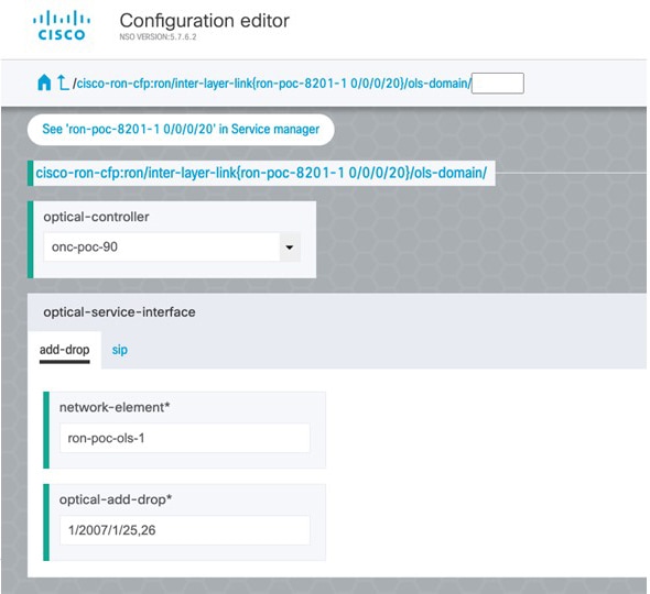
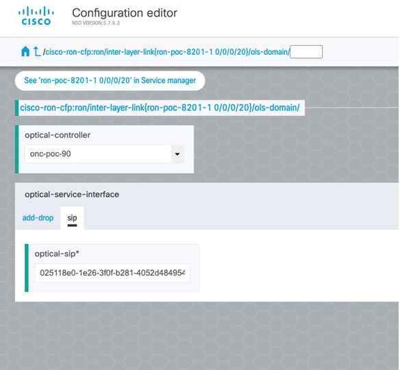
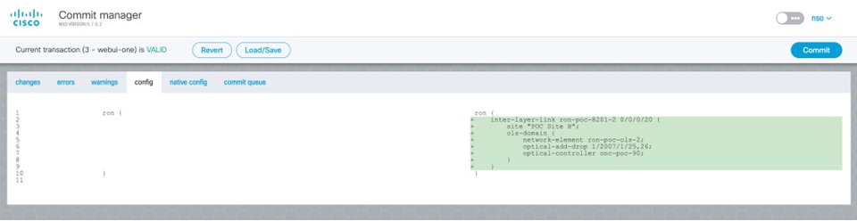
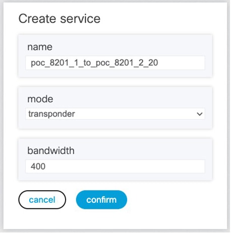
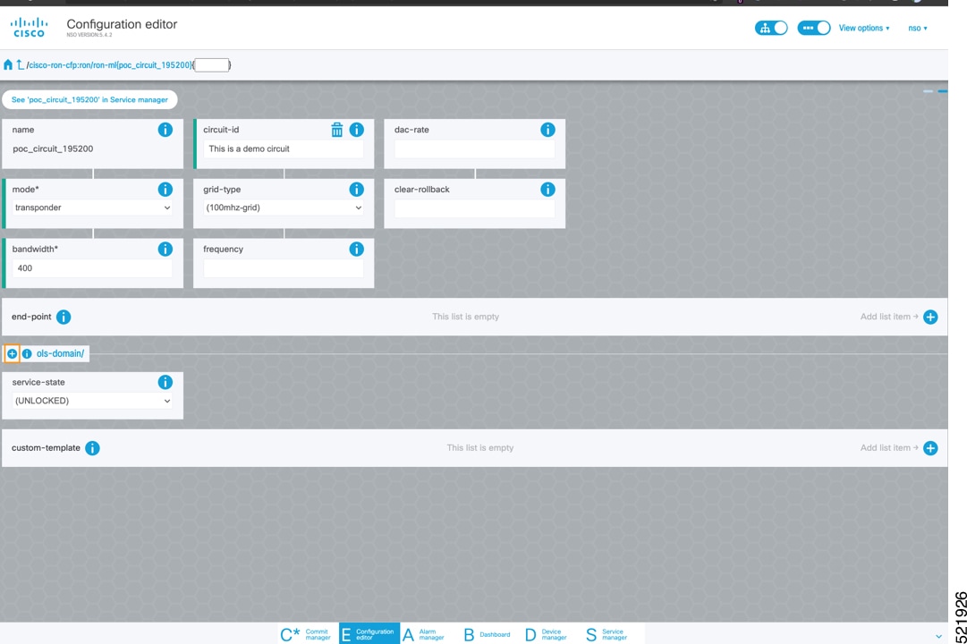
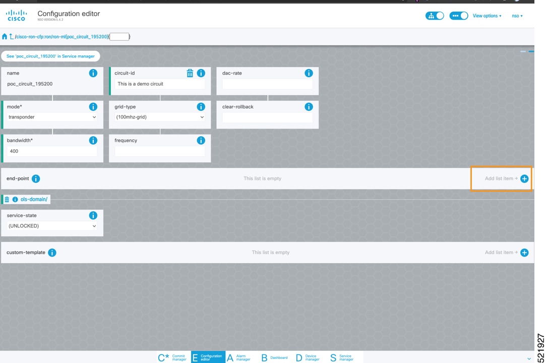
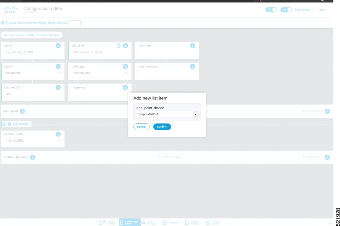
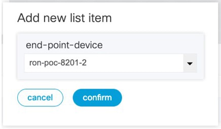
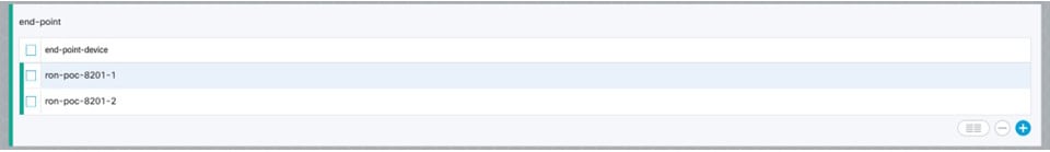
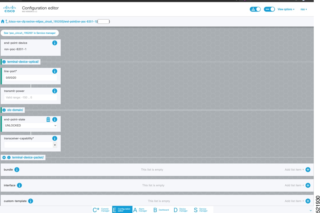
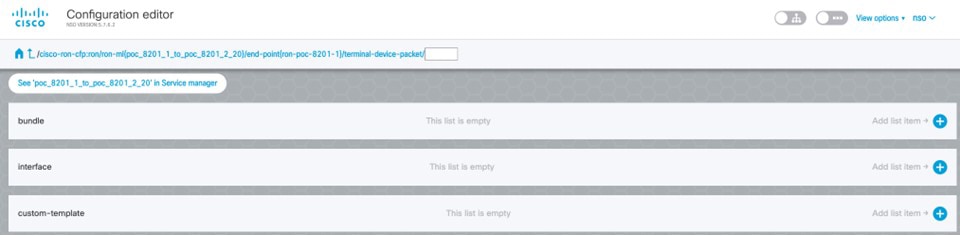
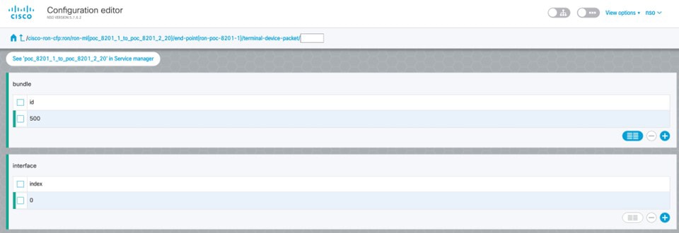
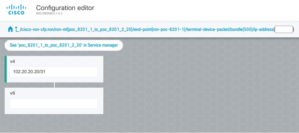
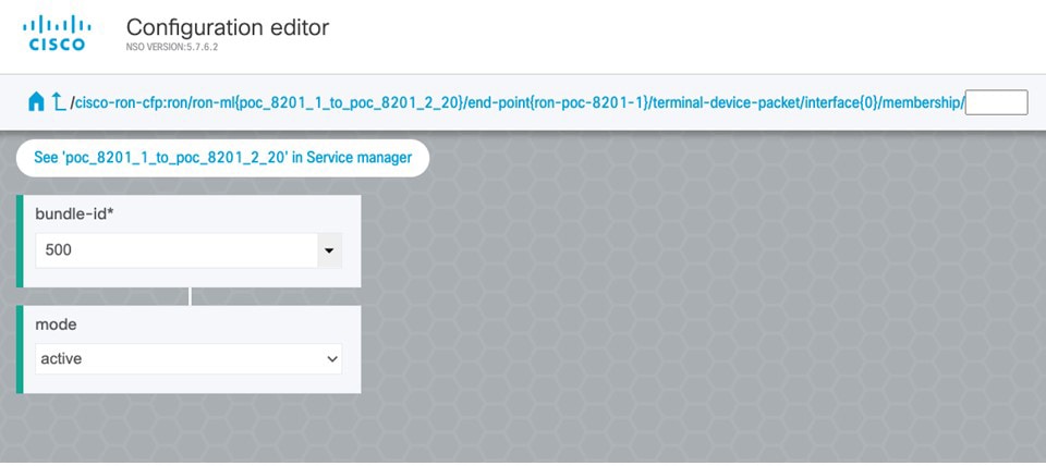
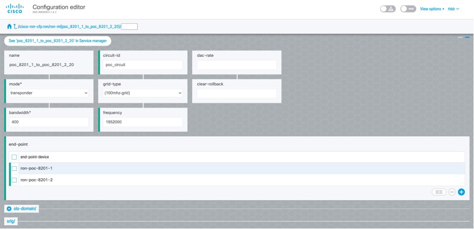
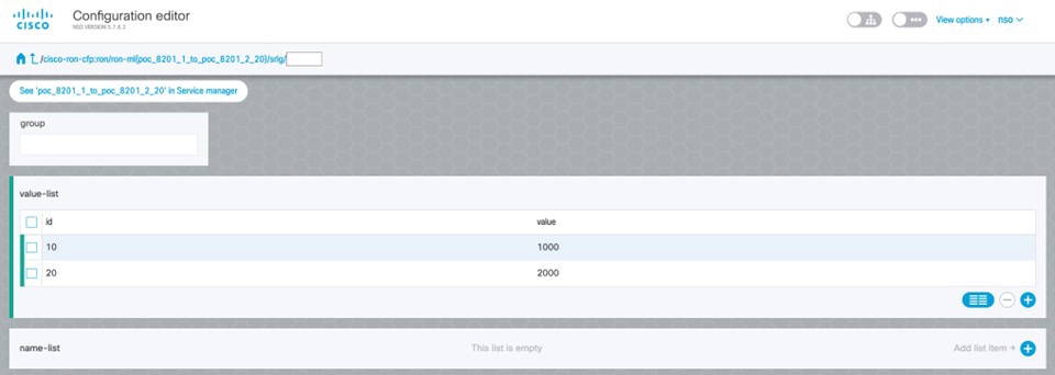
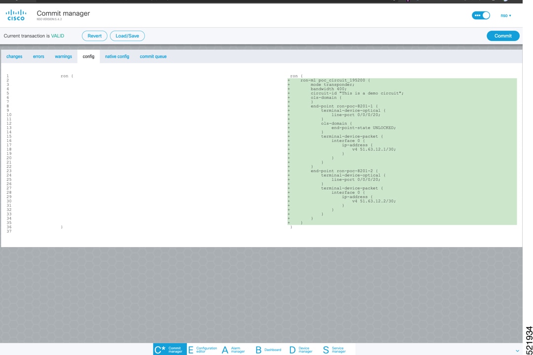
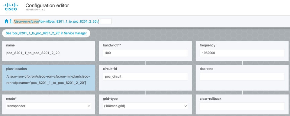
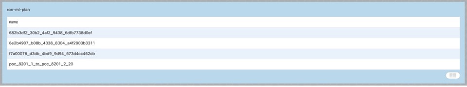
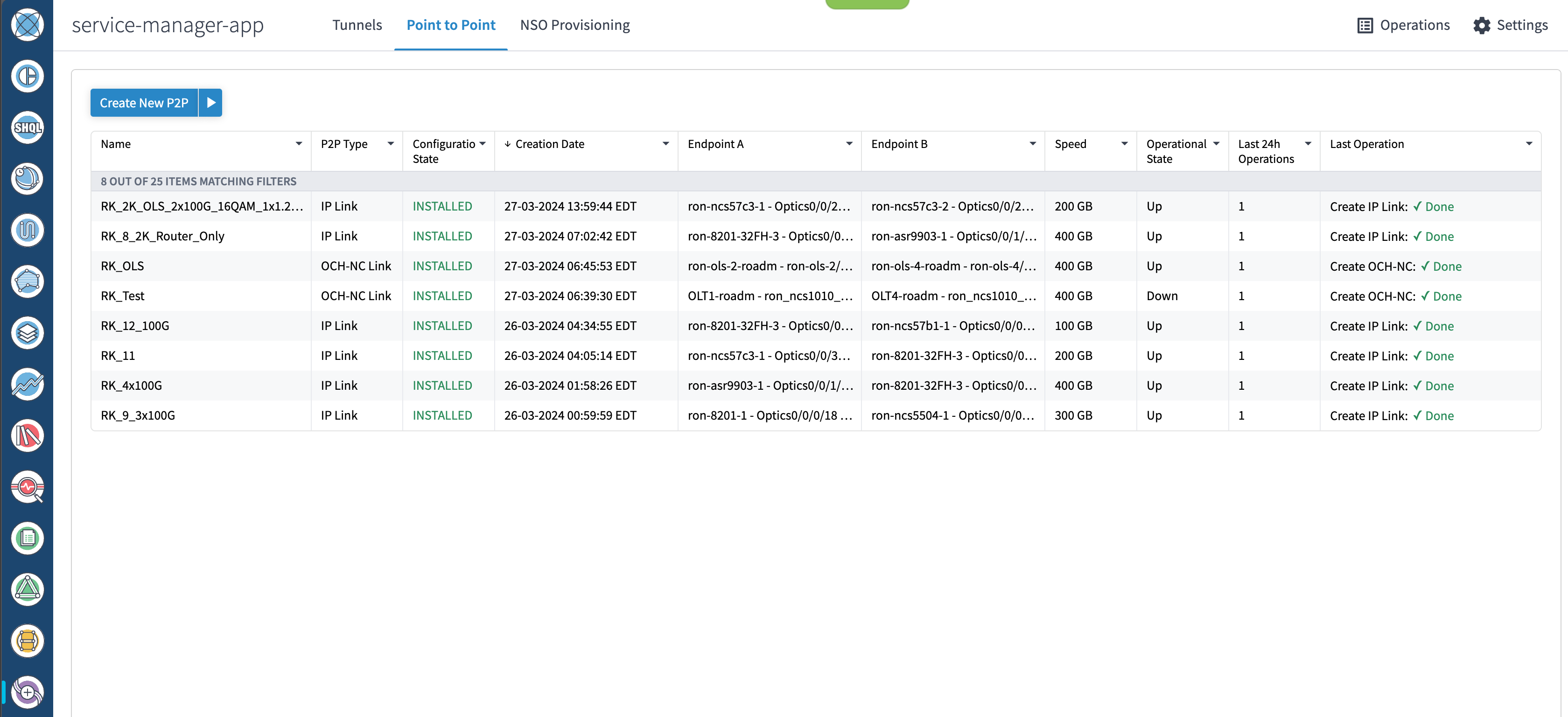
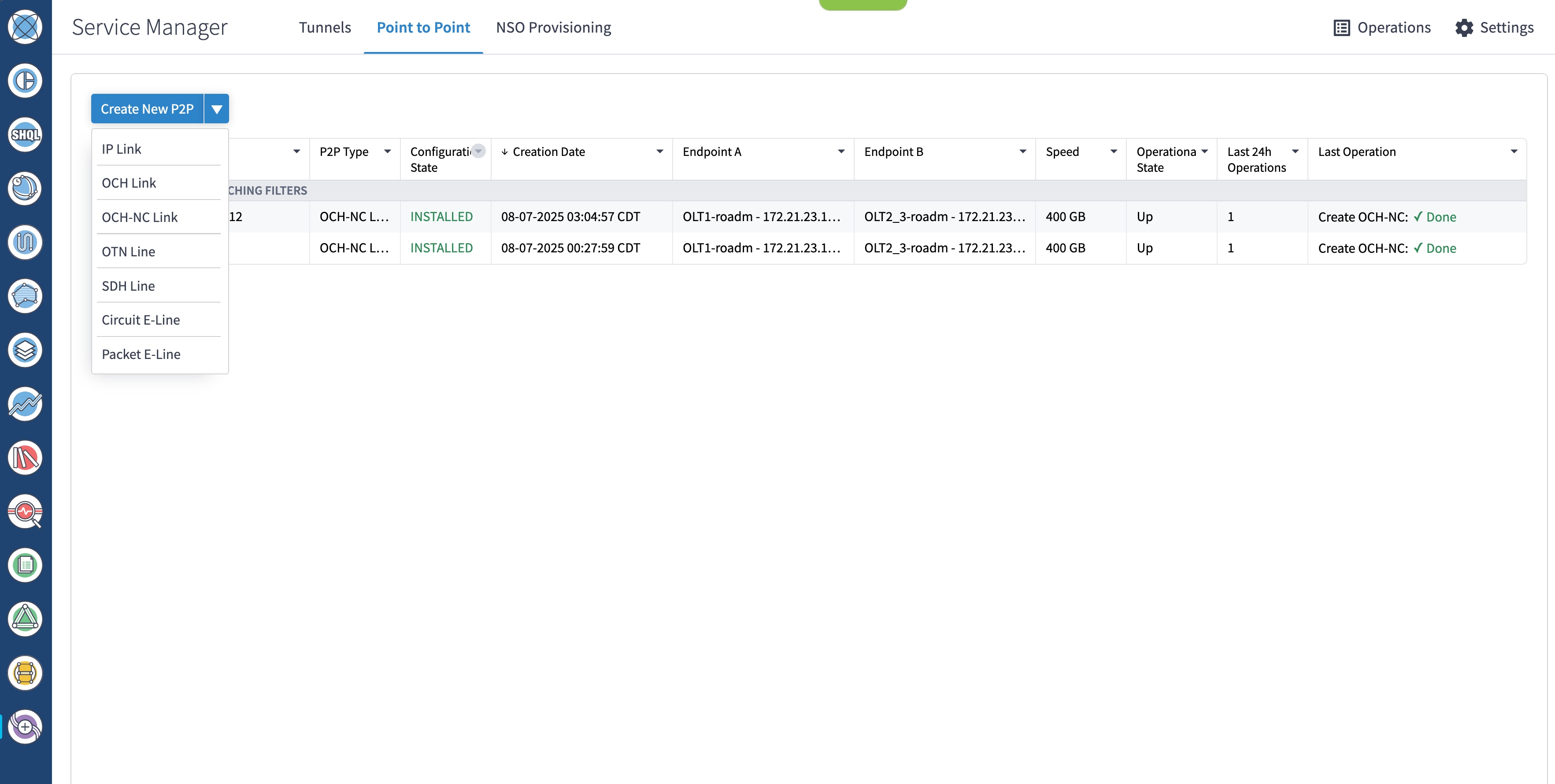
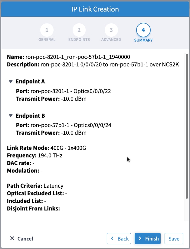
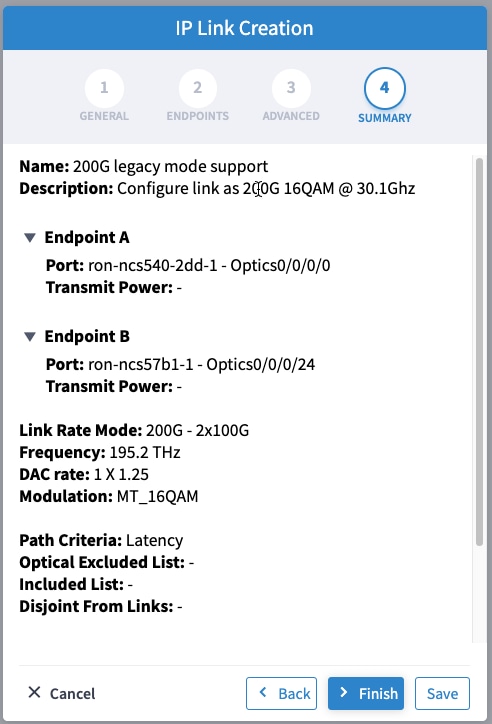
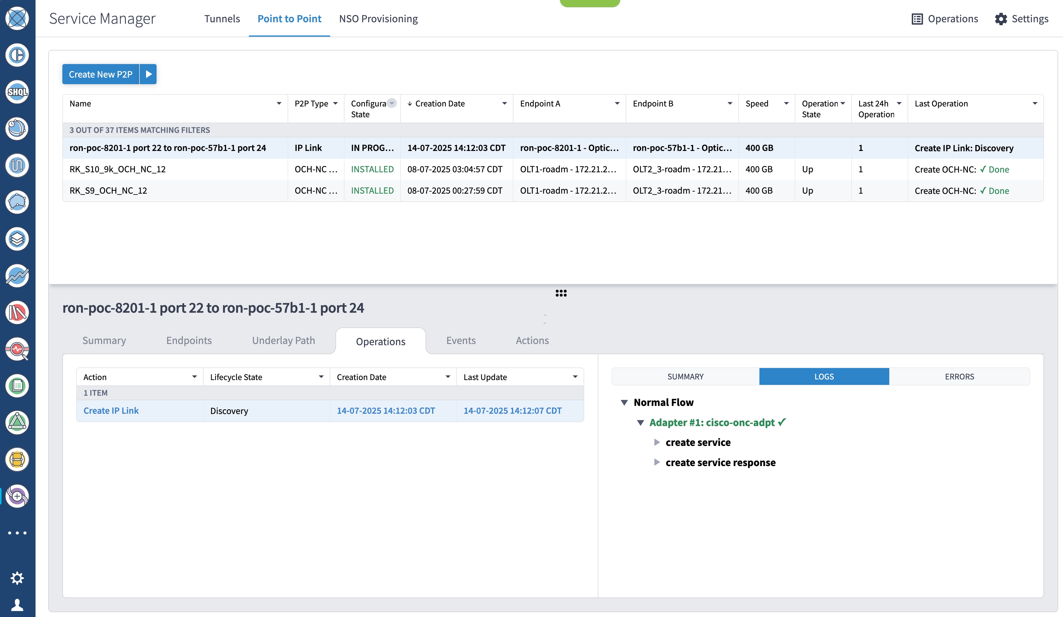
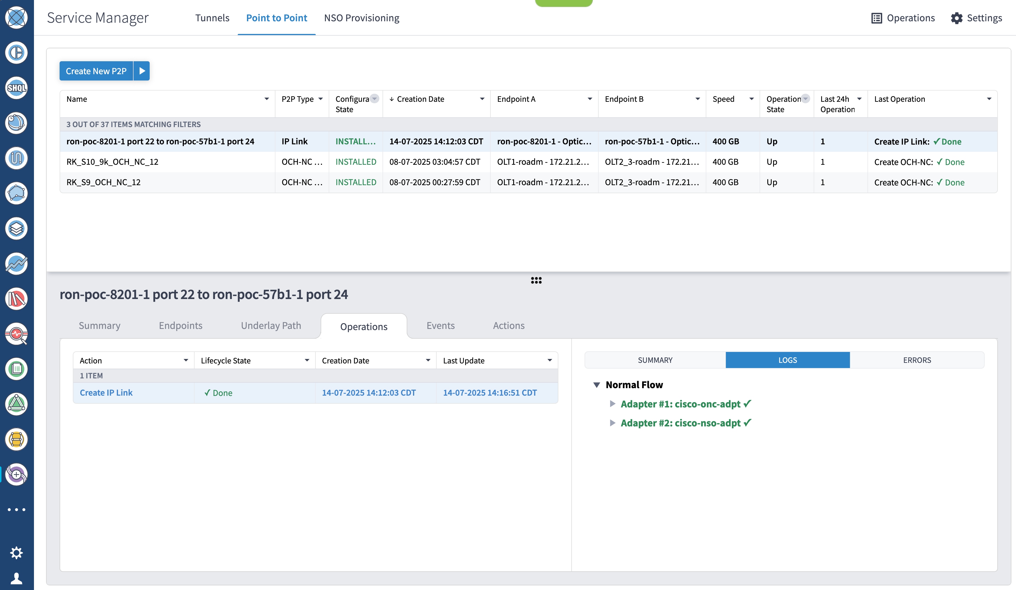
        1. Utilize the Routed Optical Networking FP ML services to provision and end-to-end service. See Provision an ML service using NSO Routed Optical Networking CFP.

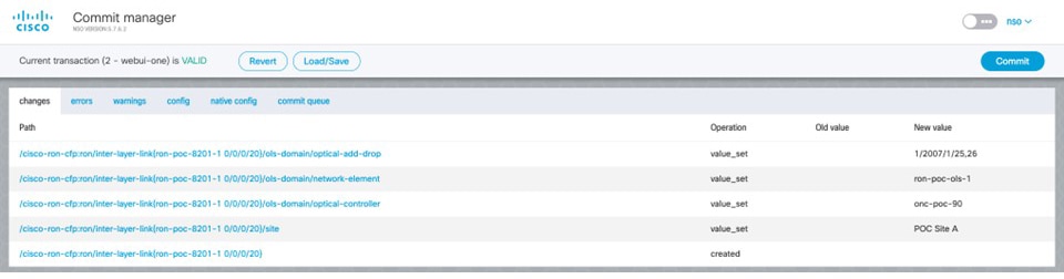
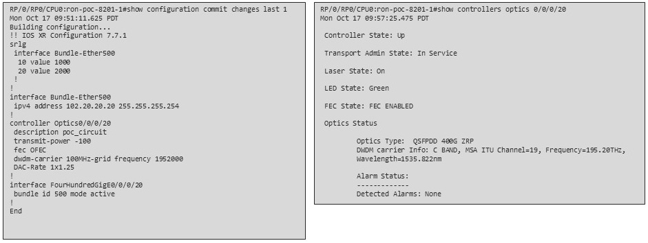
        2. Verify that the end-to-end service has been deployed by checking the NSO service deployment status using the check-sync status.

        3. Verify the router optics controller state using the CLI or in EPNM. See Troubleshoot provisioning issues on ZR or ZR+ optics.

      2. Using the Crosswork Hierarchical Controller GUI:

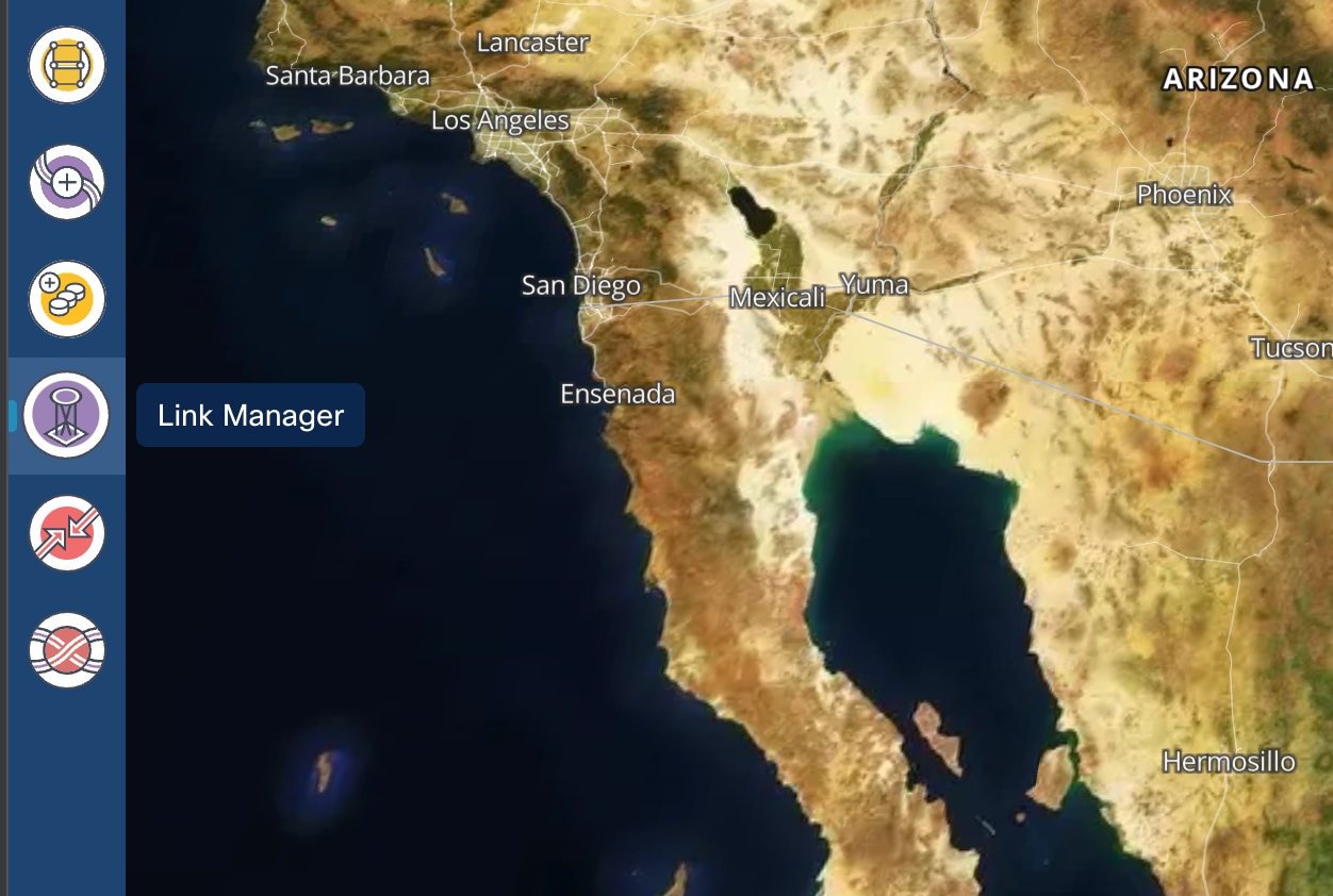
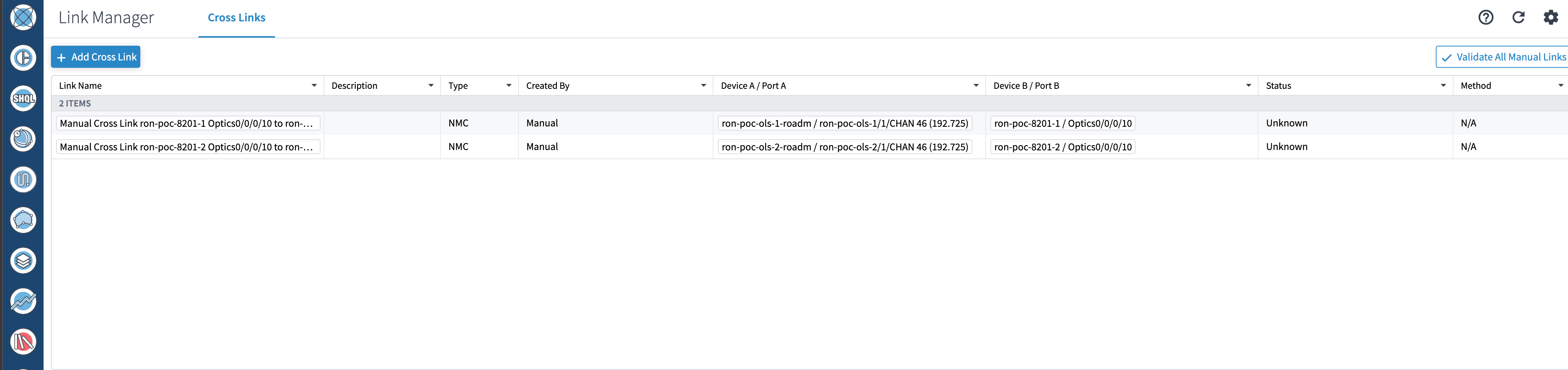
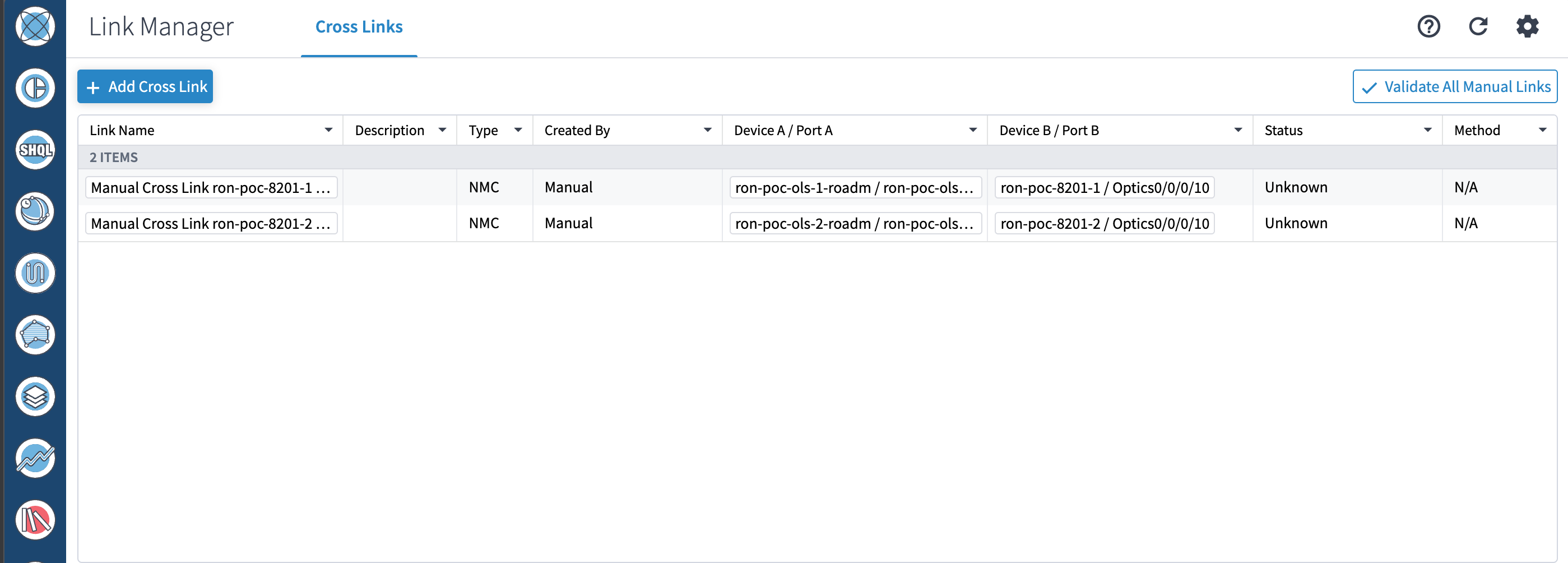
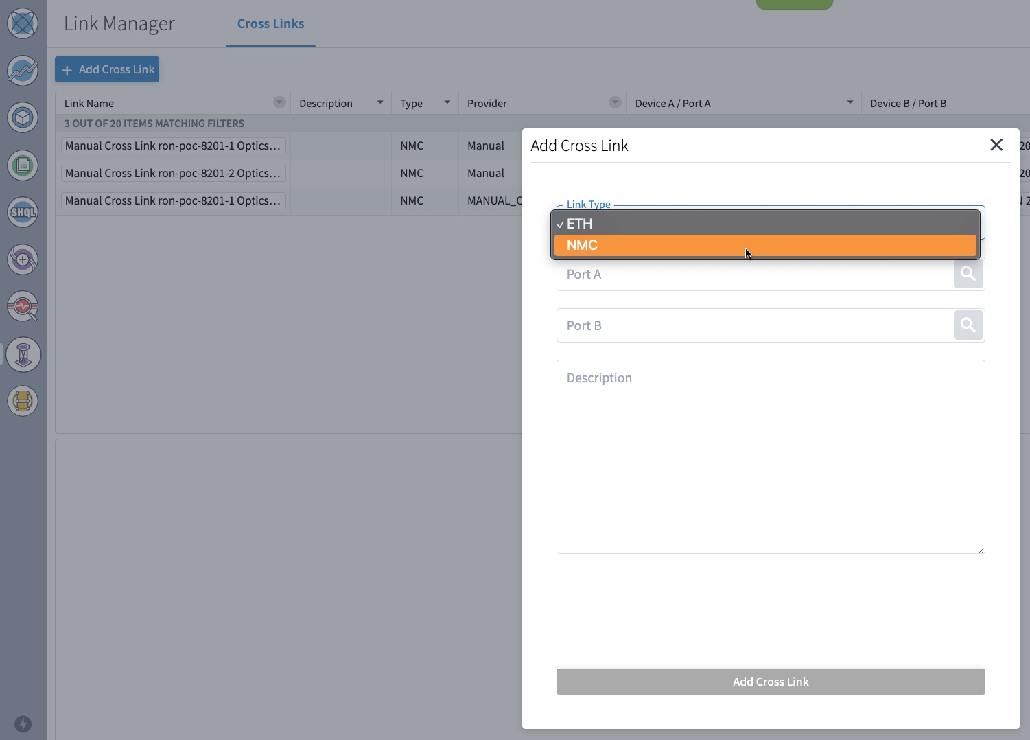
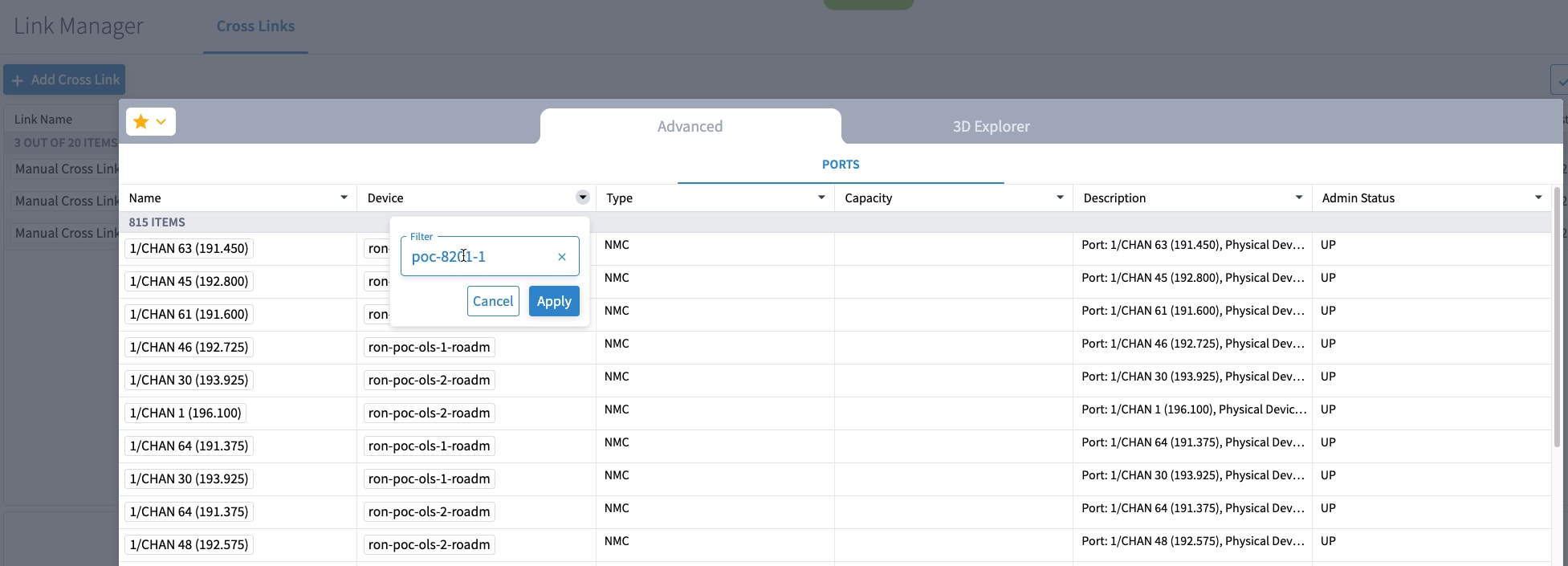
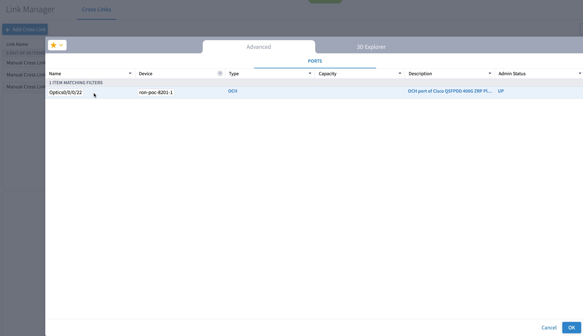
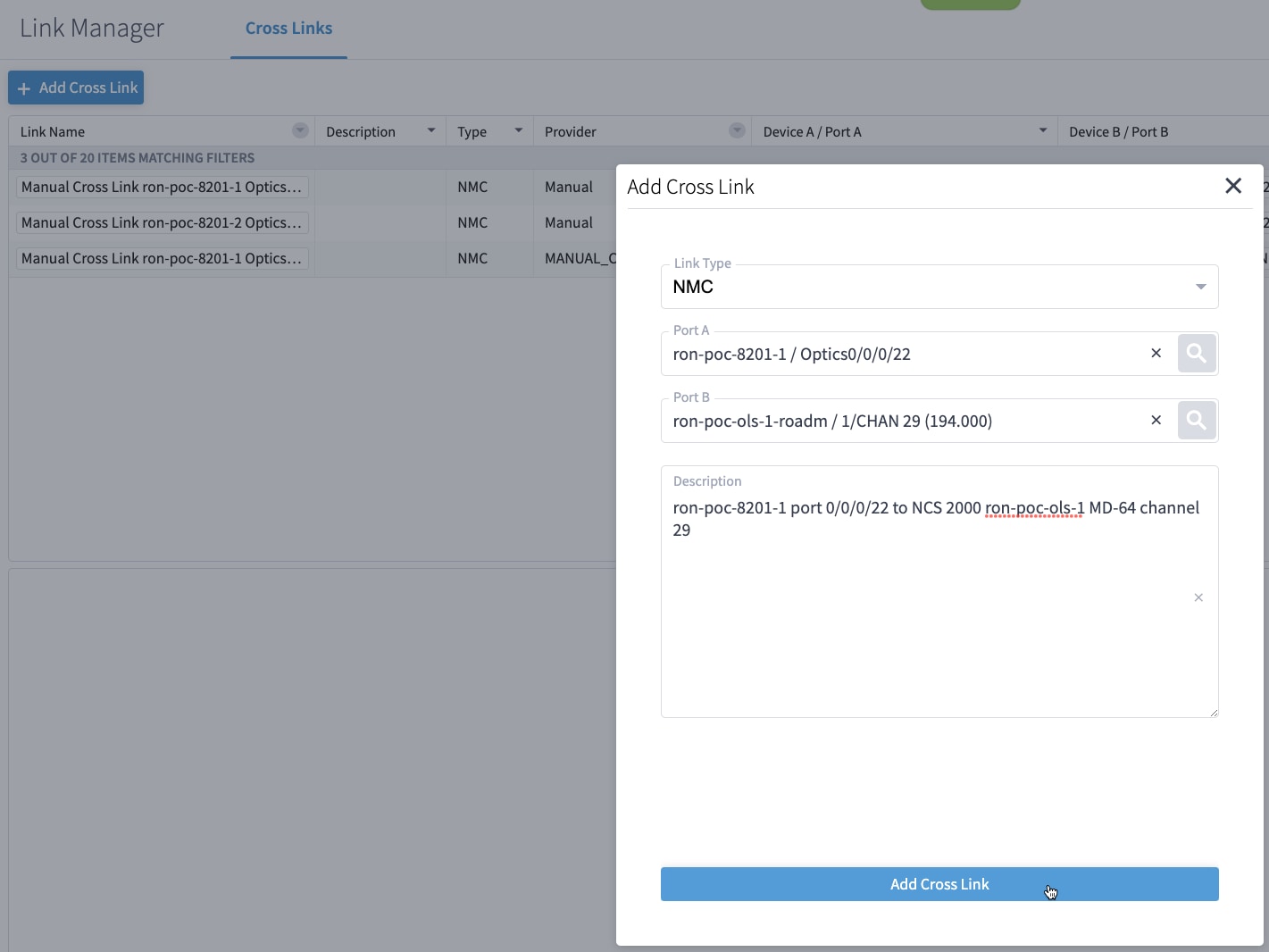
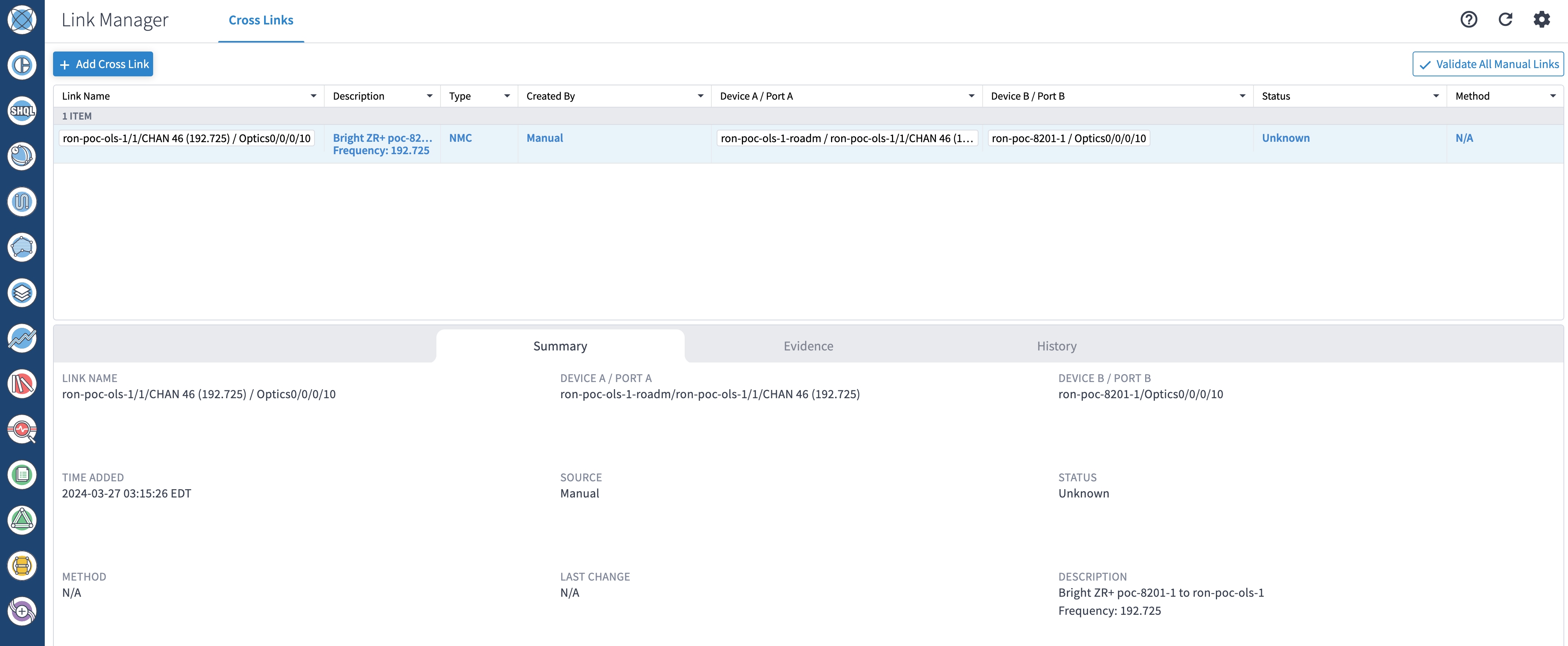
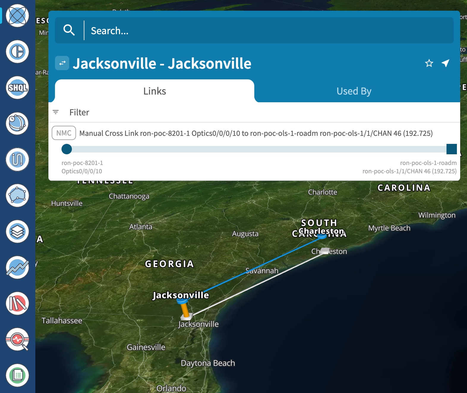
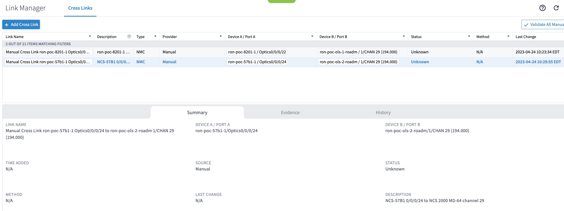
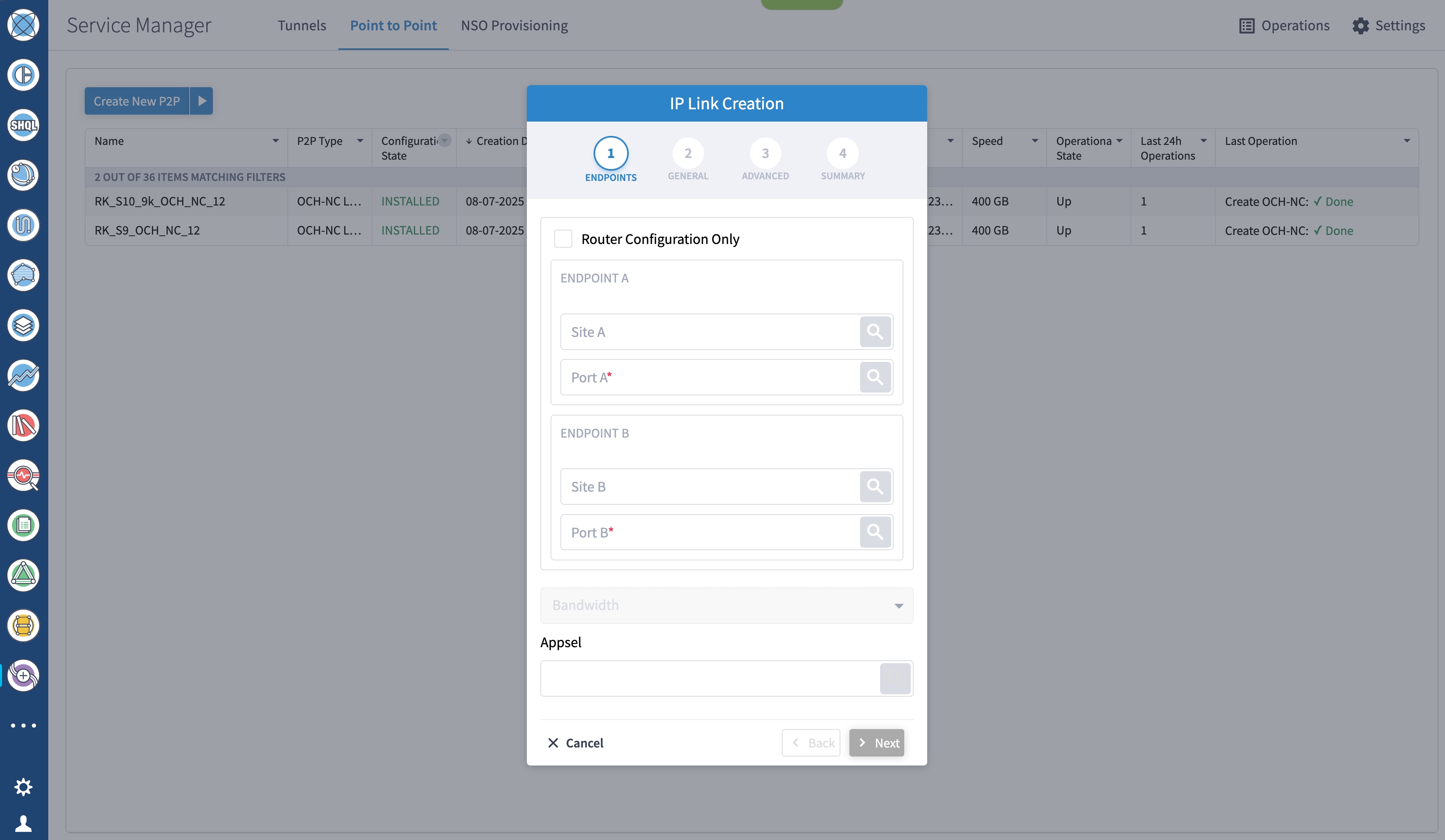
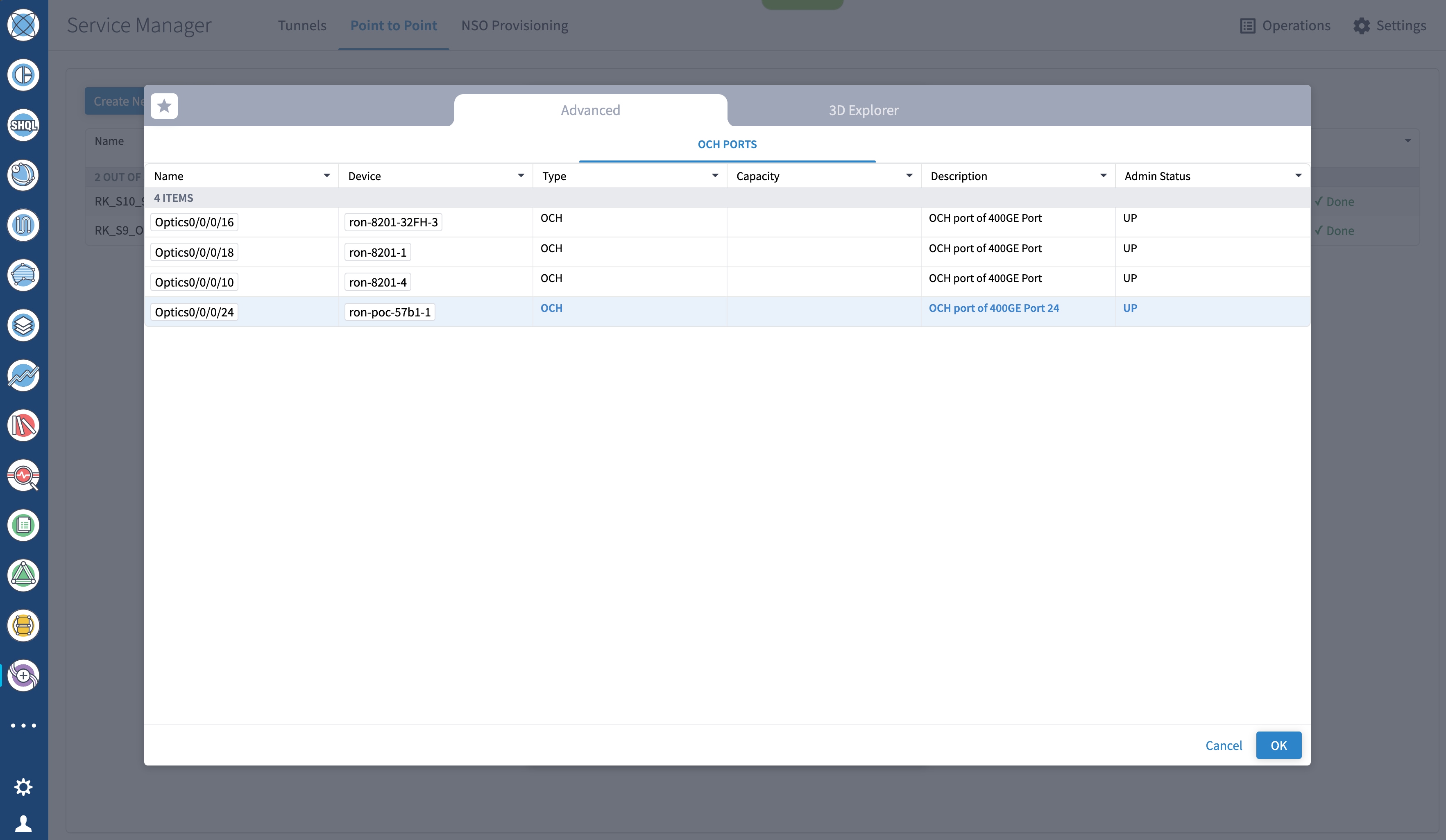
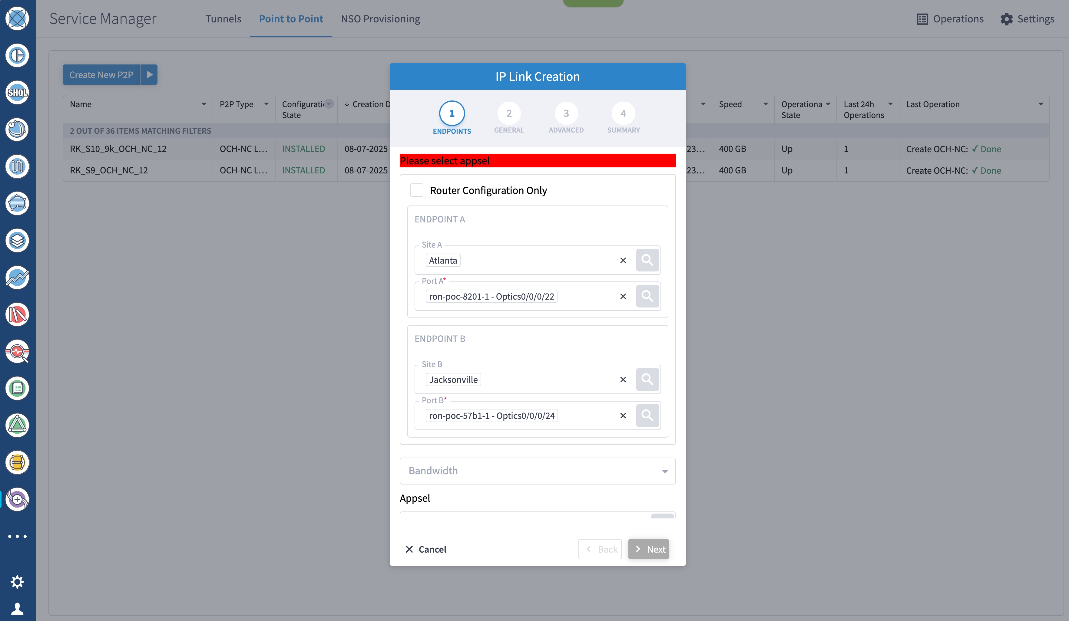
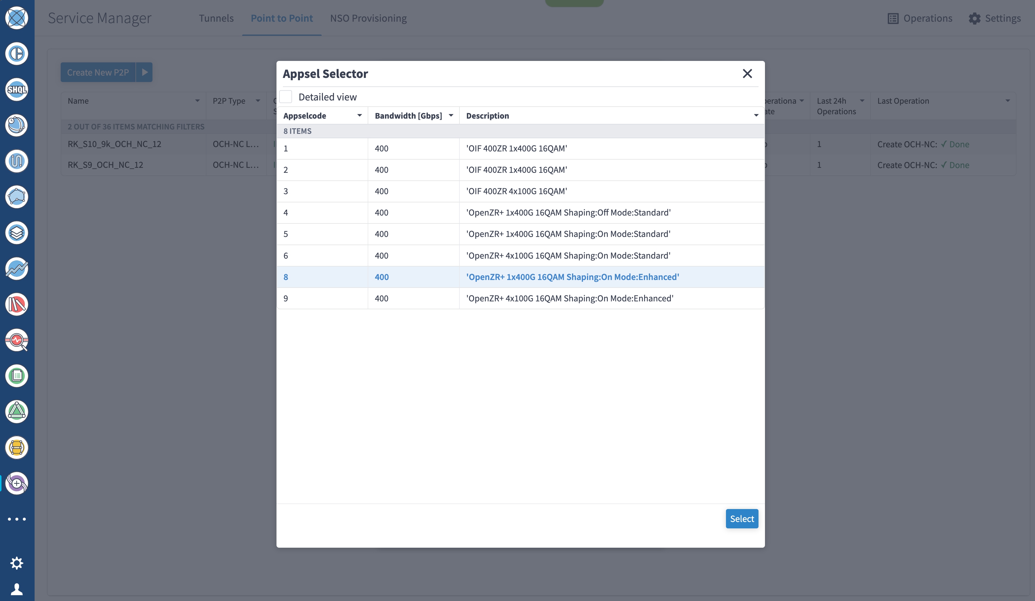
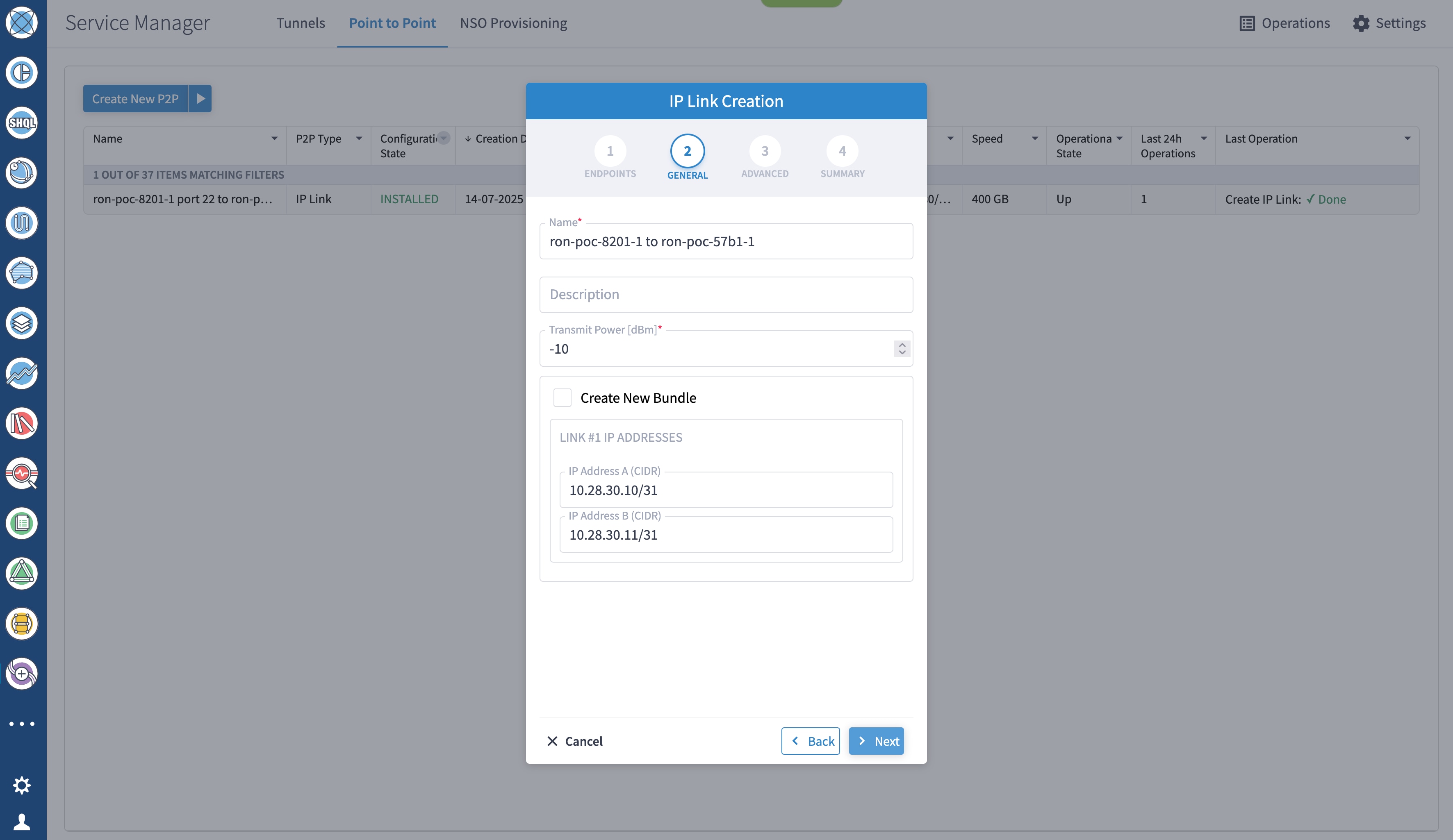
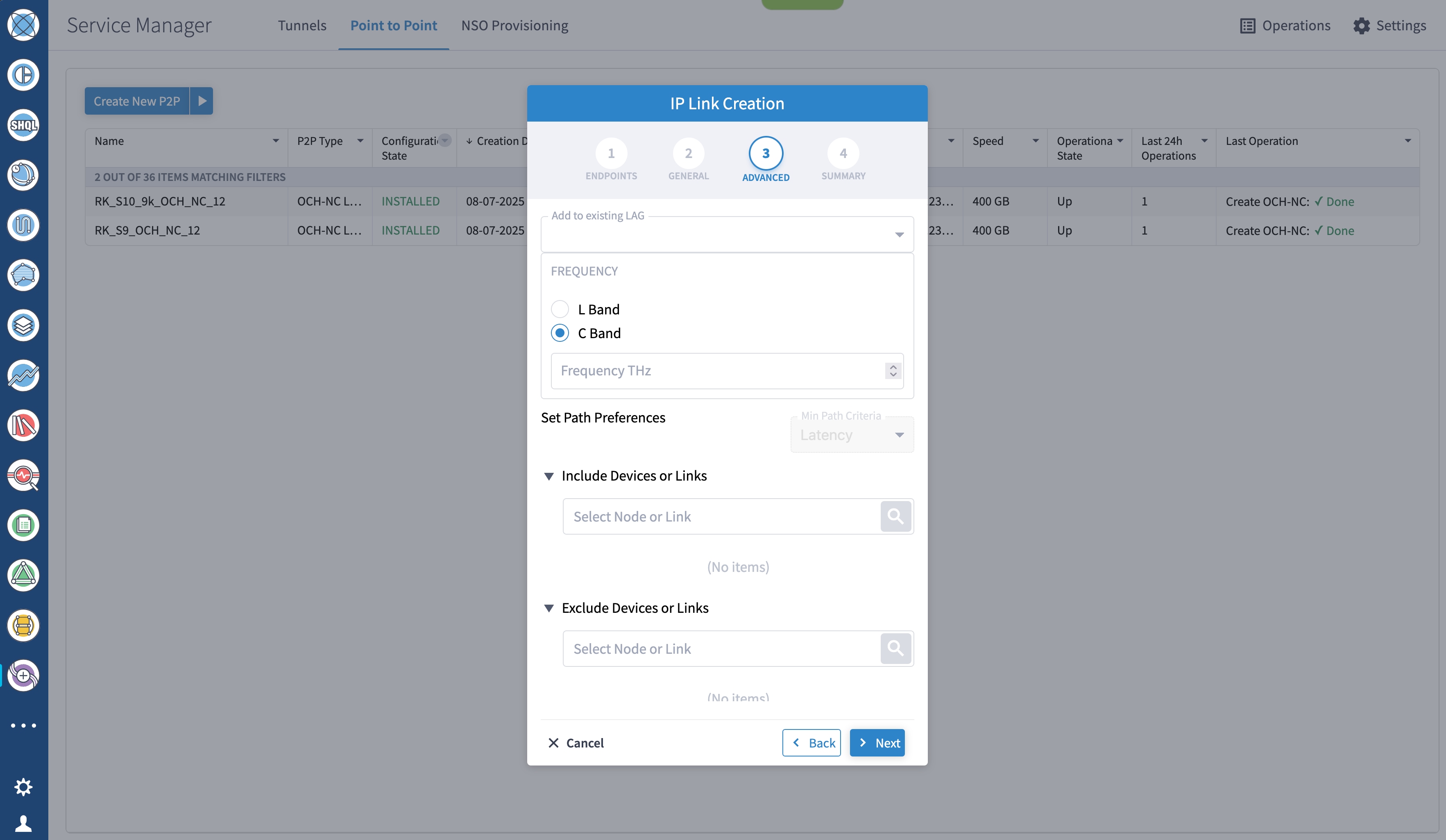
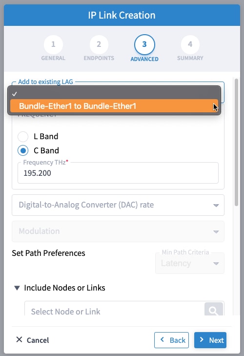
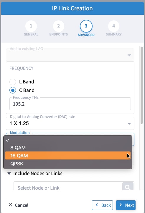
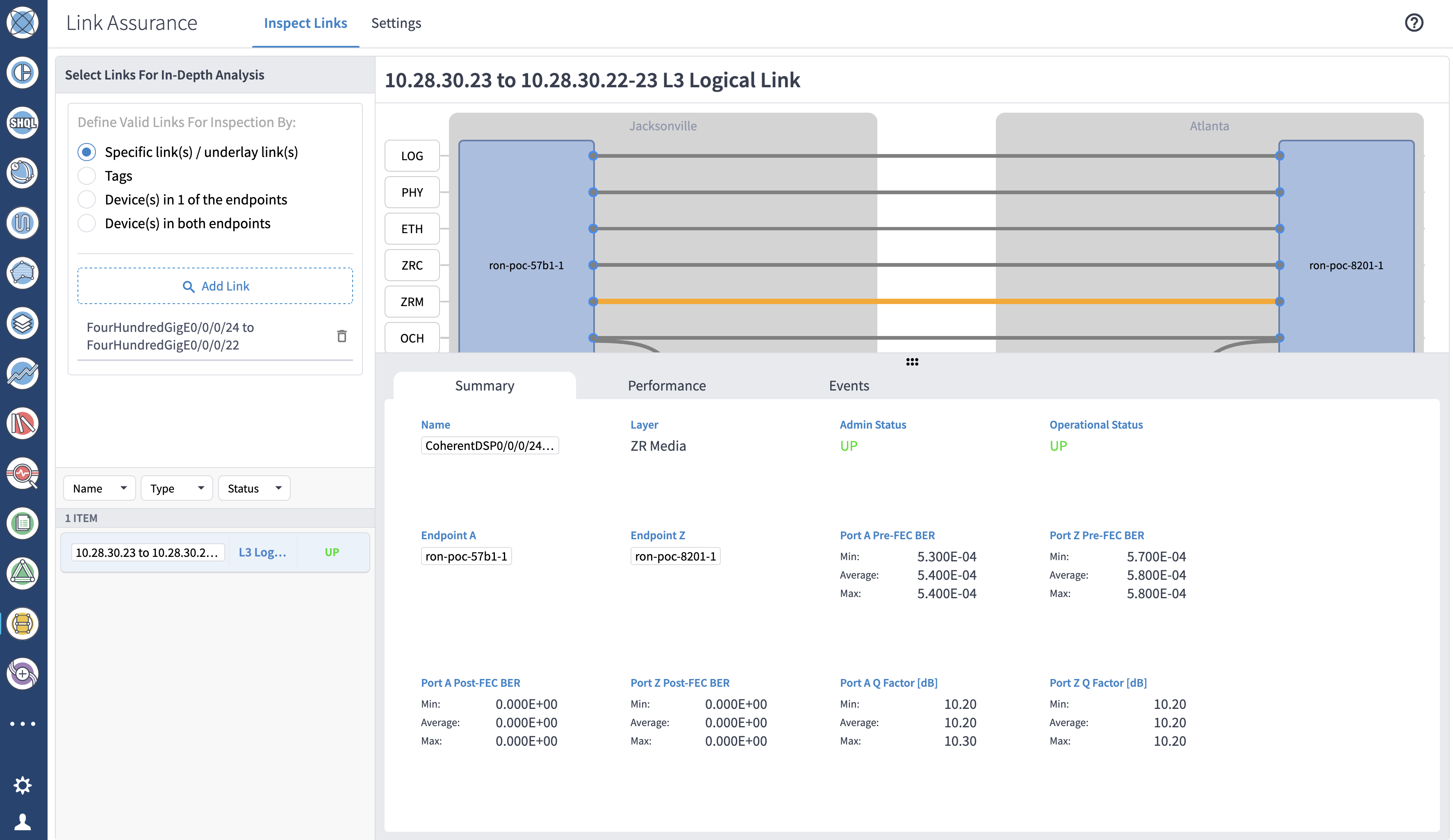
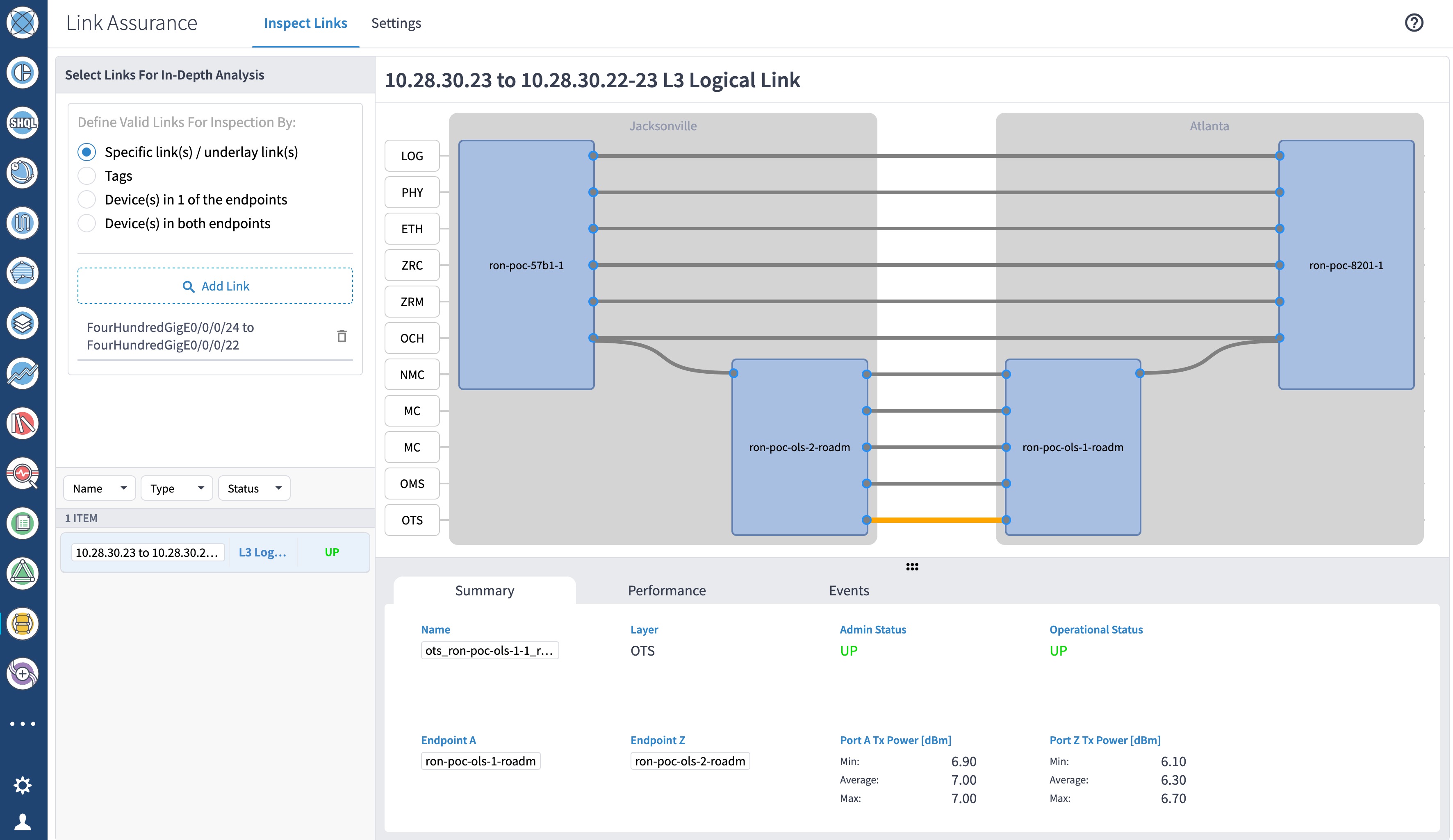
        1. Utilize the Crosswork Hierarchical Controller GUI to provision and end-to-end Routed Optical Networking ML service. See Provision a Routed Optical Networking ML service using Crosswork Hierarchical Controller.

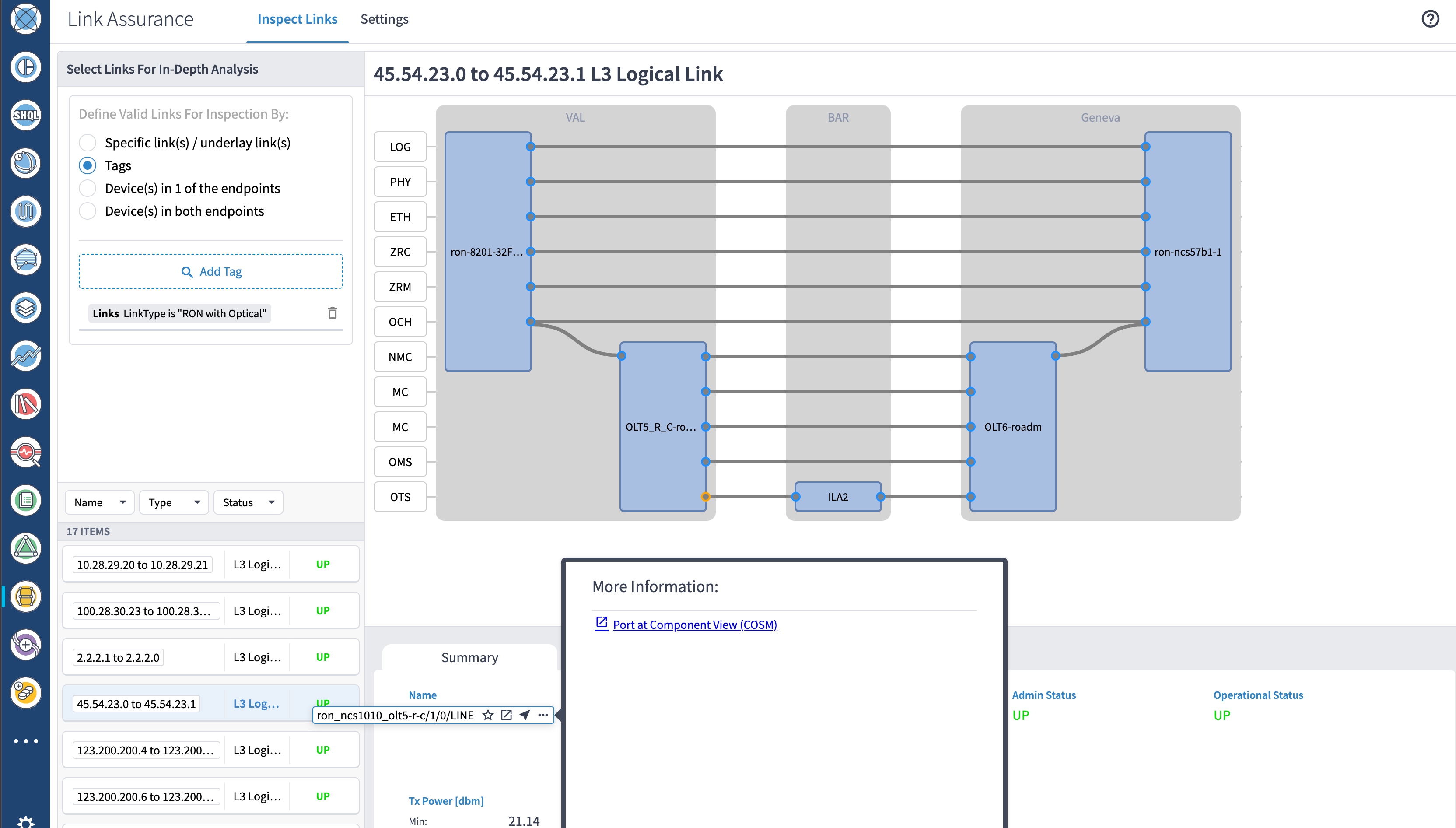
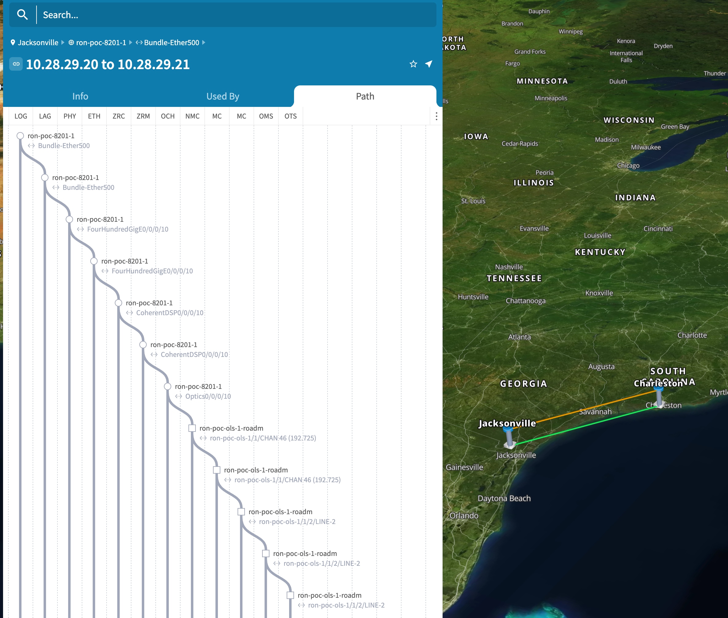
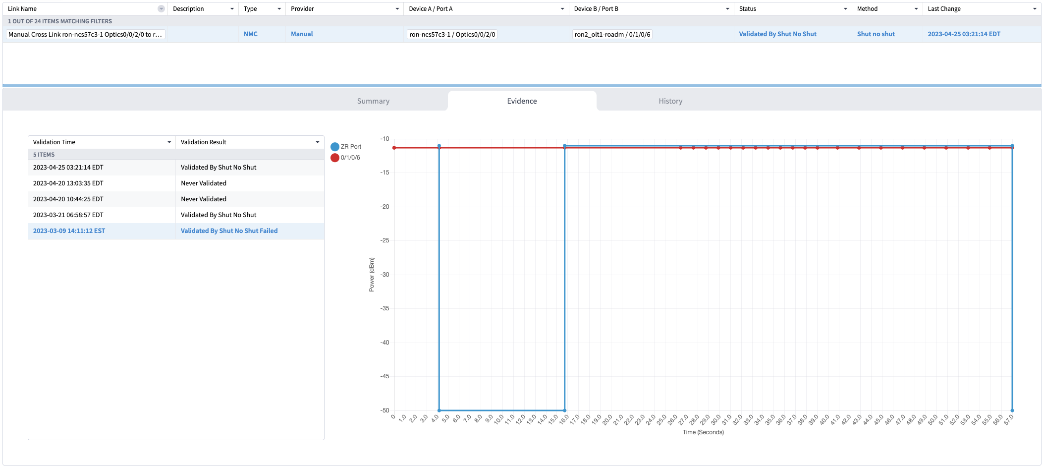
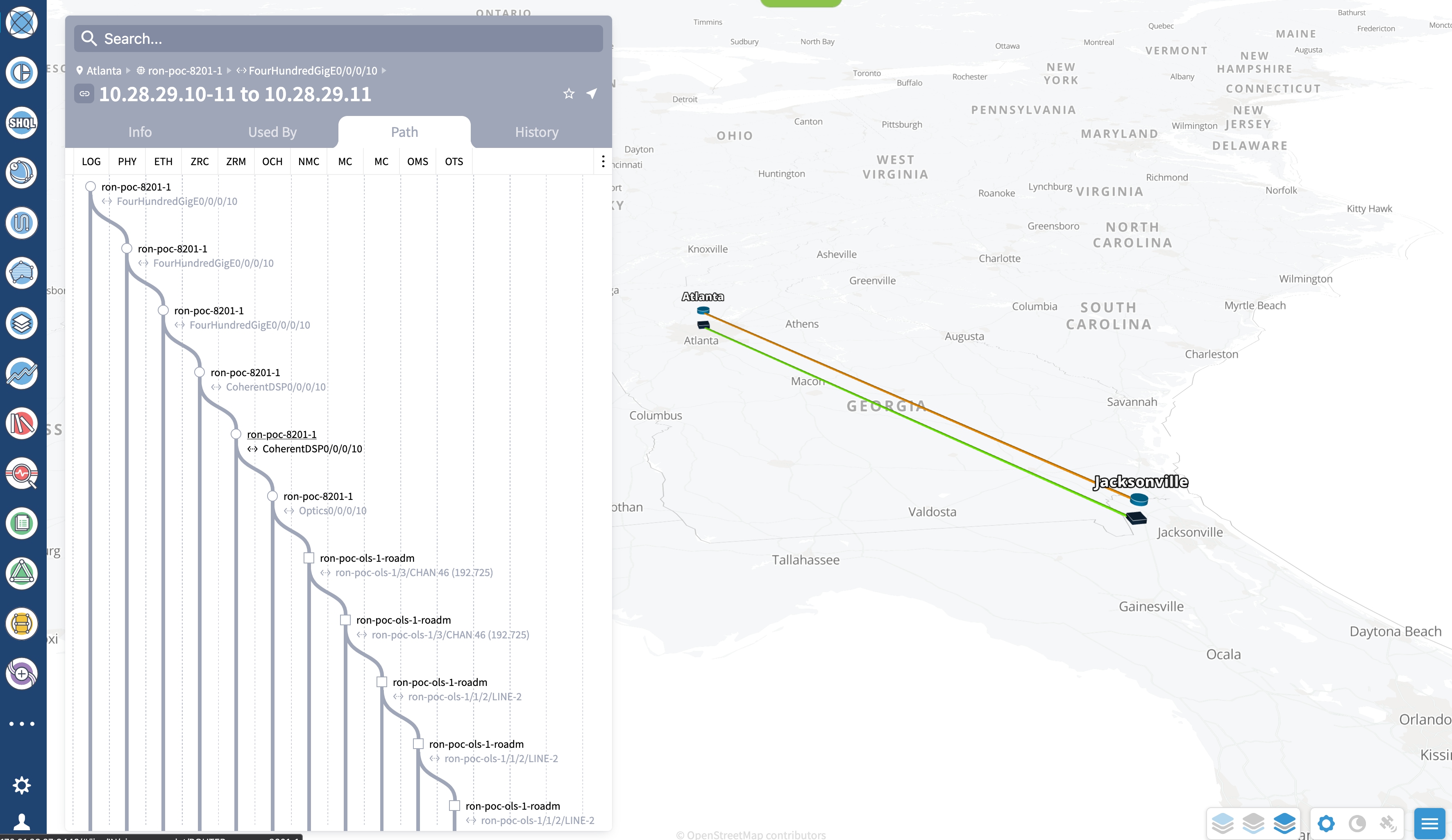
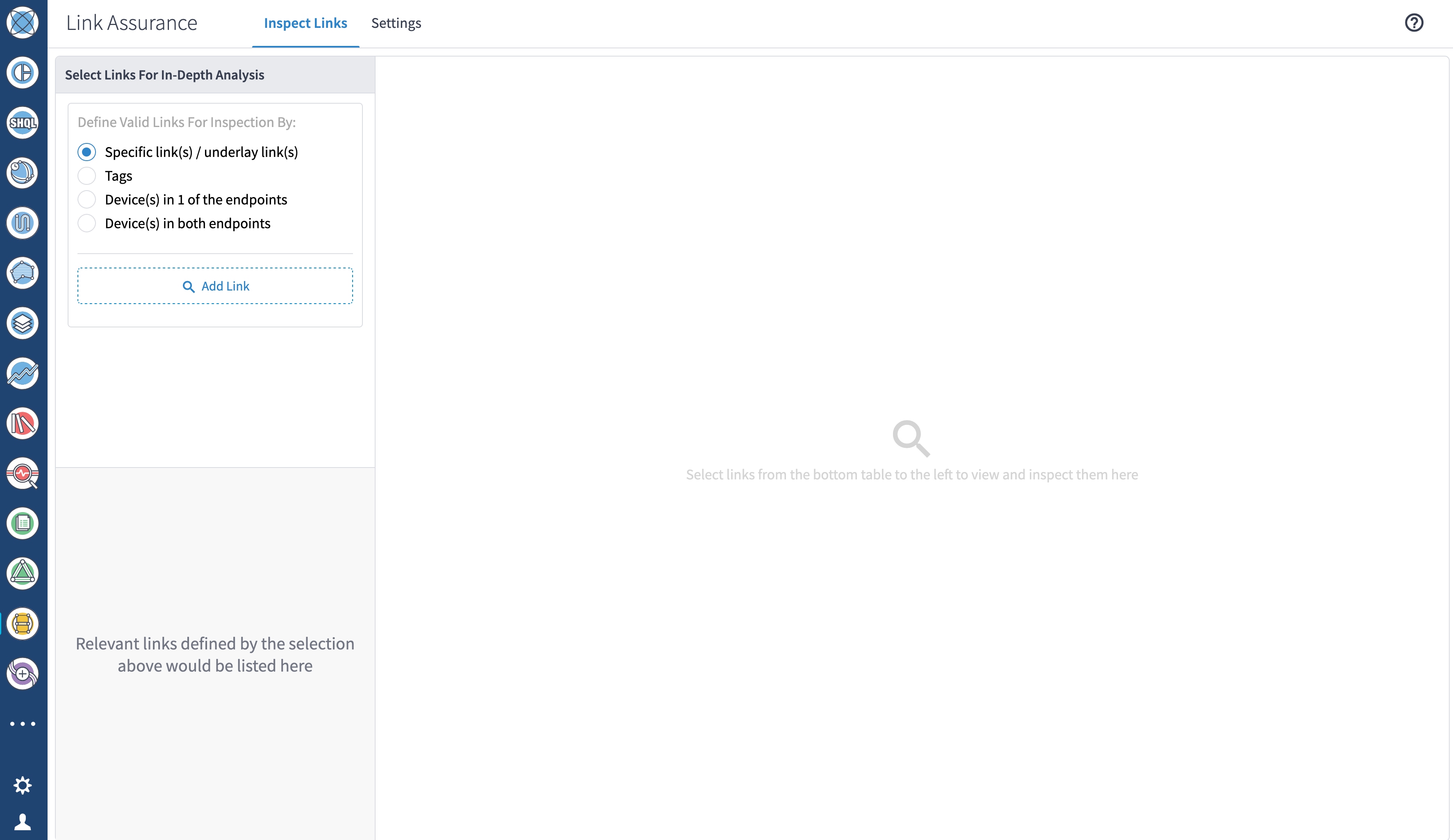
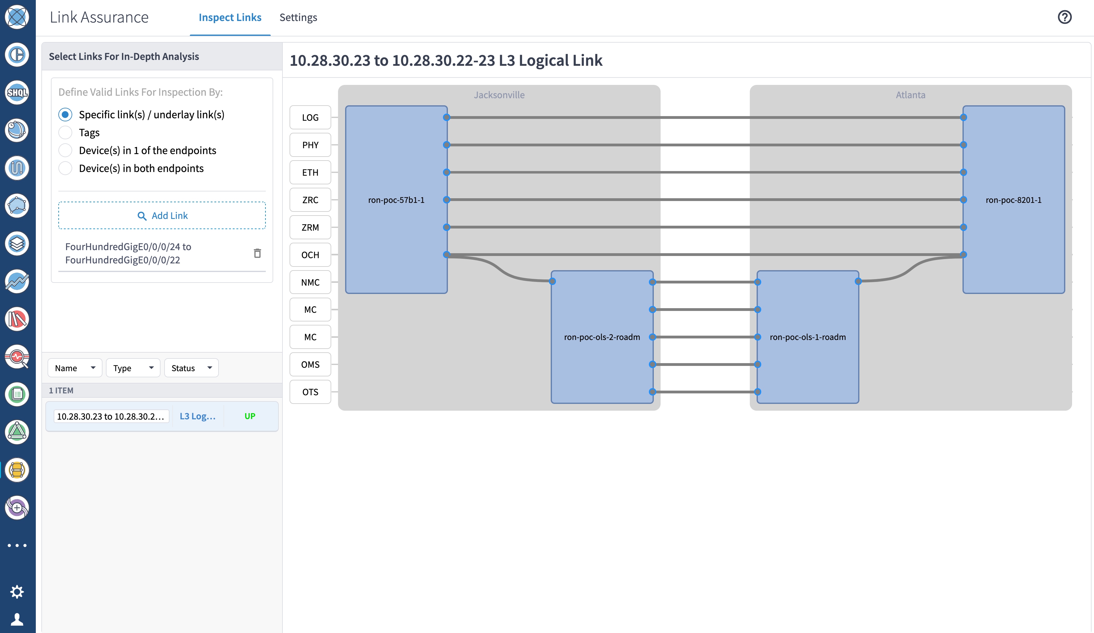
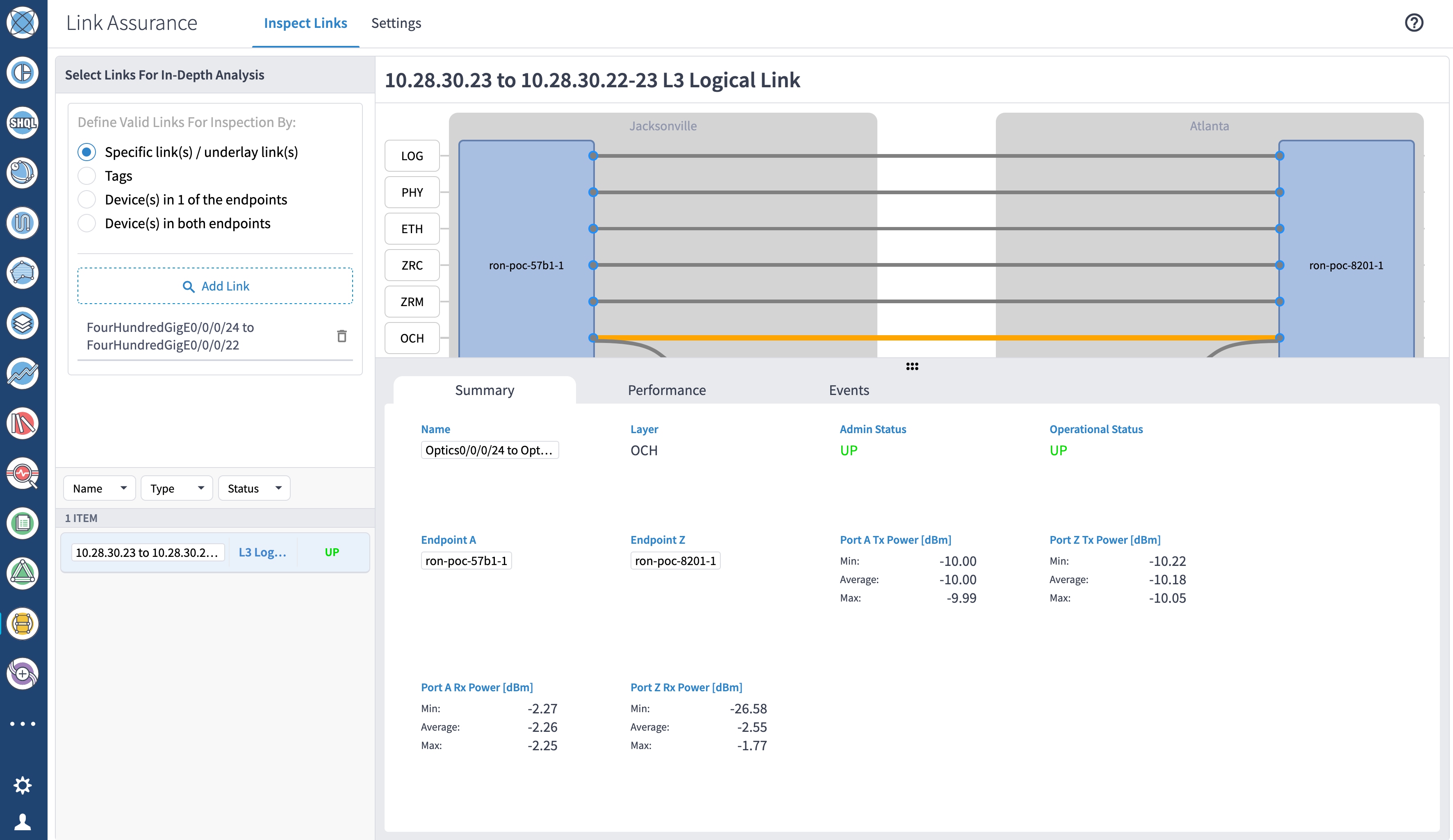
        2. Verify the router optics controller state using the Link Assurance tool in Crosswork Hierarchical Controller. See Step 4 in Provision a Routed Optical Networking ML service using Crosswork Hierarchical Controller.


Add SR-PCE providers, NSO providers, and routers to Crosswork Network Controller

Follow these steps to add SR-PCE providers, NSO providers, and routers to Crosswork Network Controller.

Note

When you add or import devices, or create providers, you need to specify the credential profile.

Procedure

1.

Log in to the Crosswork user interface.

2.

Choose Device Management > Credential Profiles from the main menu to create a credential profile. See Manage Credential Profiles.

  1. For the NSO credential profile, the connectivity type must be set to NETCONF and HTTPS. Optionally, HTTP can also be defined if HTTPS is not used in NSO.

    NSO Credential Profile
  2. The SR-PCE credential profile requires HTTP credentials to communicate with the SR-PCE Northbound API.

    SR-PCE credential profile
  3. The router credential profile requires SNMPv2 or SNMPv3 and SSH connectivity types. NETCONF is optional. Use gNMI when you configure streaming telemetry sensors on the node.

    Router credential profile
3.

Add the providers. See About Adding Providers.

  1. Choose Administration > Manage Provider Access from the main menu to add the SR-PCE or NSO provider. See Manage Providers.

  2. Add the NSO provider. See Add Cisco NSO Providers.

    Select the credential profile created for NSO. Select the family as NSO. The Device Key may be set to either HOST_NAME or INVENTORY_ID, depending on the specific deployment.

    This image shows the connectivity to the RESTCONF API for NSO over SSL using port 8888 and NETCONF using the default port number 2022. Since the Routed Optical Networking NSO CFP utilizes the XR CLI NED, the Cisco-IOS-XR model is not applicable and may be set to any version.

    Edit NSO provider
  3. Add the SR-PCE provider. See Add Cisco SR-PCE Providers..

    Select the credential profile created for SR-PCE. Select the family type as SR_PCE. The connectivity type for SR-PCE must be HTTP. In this image, the default API port of 8080 is specified. When the Property Key, "auto-onboard" is set to a Property value, "off", Crosswork Network Controller does not automatically add nodes that are discovered via the SR-PCE IGP topology to the device inventory. Devices must be added through the Crosswork Network Controller UI or inventory API.

    Edit SR-PCE provider
4.

Validate communications with one or more providers. Check the reachability of the provider using Get Provider Details.

5.

Onboard devices. See Add Devices Through the UI.

  1. The Administration State, Reachability Check, and Credential Profile are mandatory elements. The Host Name must be used if the NSO provider device key is set to the Host Name value. If the NSO provider device key is set to Inventory ID that field must be populated. The Software Type, Software Version, UUID, Serial Number, MAC address, and Product Type are filled by device discovery. Optionally, tags can be applied to the device. The GNMI encoding type can be set to JSON or PROTO.

    Add new device

    Optionally, you can enter location information. Latitude and longitude information is used to specify the node’s geographic location.

    Add the previously configured NSO provider as a provider for the device.

    Add new device
  2. Attach the devices to an active Cisco Crosswork Data Gateway pool to manage them (device discovery).

    Review the Data Gateways pane (see Overview of Cisco Crosswork Data Gateway). The operational state of the Cisco Crosswork Data Gateway pool to which you want to attach devices must be Up.

    See Attach Devices to Cisco Crosswork Data Gateway.

    Data gateways pane

SR-PCE providers, NSO providers, and routers appear in Crosswork Network Controller and are ready for management and monitoring.


Configure adapters for Routed Optical Networking in Crosswork Hierarchical Controller

These adapters are needed for the Routed Optical Networking solution.

Table 1. Routed Optical Networking adapters

Adapter

Credential type

Crosswork Network Controller

HTTP (username and password)

Cisco Optical Network Controller

HTTP (username and password)

Note

If Cisco Optical Network Controller and Crosswork Network Controller are on the same Crosswork cluster, use the same credential profile for both.

Before you begin

To use Crosswork Hierarchical Controller adapters, you are required to use credentials. These credentials are used for authentication when a device is assigned to an adapter. You can use the same credentials for multiple adapters.

The credentials are added under the Services > Device Manager > Credentials tab in the Crosswork Hierarchical Controller GUI.

Follow these steps to add the adapters:

Procedure

1.

Choose Services > Device Manager > Adapters in the applications bar in Crosswork Hierarchical Controller.

2.

Click Add new adapter to add a new adapter.

3.

Enter the adapter details:

  • Adapter Type: Select an adapter type from those available and currently installed in Crosswork Hierarchical Controller.

  • Adapter Name: Enter a unique name for this adapter type instance. Multiple instances of the same adapter type are allowed.

4.

Select the adapter in the Adapters pane to configure the adapter. Configure the parameters as shown in these images.

  • Crosswork Network Controller adapter:

    Note

    API version for Crosswork Network Controller must be version 2.

    Figure 1. Crosswork Network Controller adapter configuration—General tab
    Note

    The Full Data Fetch Interval must be set to 300 seconds or higher in a production network.

    These parameters must be configured for Crosswork Network Controller notifications and collection.

    Figure 2. Crosswork Network Controller notifications
    Crosswork Network Controller notifications
    Figure 3. Crosswork Network Controller collection and provisioning
    Crosswork Network Controller collection and provisioning
  • Cisco Optical Network Controller adapter

    Figure 4. Cisco Optical Network Controller adapter — General tab

    The Polling cycle must be set to 300s or higher in a production network. Polling retrieves TAPI SIPs, topology, and connectivity services.

    The URL in this figure is for the Cisco Optical Network Controller 3.1.

    IOS-XR Adapter - collection settings

    Cisco Optical Network Controller automatically discovers optical nodes. Assign a site to the nodes to display them in the Explorer UI.

    Figure 5. Cisco Optical Network Controller adapter - Devices tab
  • NSO adapter In Hierarchical Controller

    In Hierarchical Controller 11.0 there is an embedded NSO installed when Hierarchical Controller 11.0 is installed. The NSO adapter can use the internal NSO or an external NSO instance. To provision devices using the NSO adapter, add the NSO adapter to the devices.

    Use the NSO adapter when you use the Automation starter solution and full solution.

    Note
    • If using the internal NSO, the Routed Optical Networking 4.0 Core Function Pack must be installed on the NSO instance.

    • If using the internal NSO, devices must be added to that NSO, since adding them to Hierarchical Controller does not automatically onboard them into the internal NSO.

    Figure 6. NSO adapter—General tab
    NSO adapter - General tab

    Begin configuring your NSO and IOS-XR adapters.

The selected adapters are configured and ready for device assignment.


Configure SSO in Crosswork Hierarchical Controller

Enable Single Sign-On (SSO) in Crosswork Hierarchical Controller using Crosswork Network Controller as the identity provider.

Use this task when you need to configure SSO in Crosswork Hierarchical Controller with Crosswork Network Controller as Identity Provider. You can use the same SSO configuration to set up SSO for Cisco Optical Network Controller Release 3.1.

Procedure

1.

Configure Crosswork Hierarchical Controller.

  1. Click Settings > Security > SAML Configuration.

    Enter the required information:

    • Login URL: Visit https://<CNC_IP_address>:<port>/crosswork/sso/idp/profile/SAML2/Redirect/SSO

    • Entity ID: Visit https://<CNC_IP_address>/idp

    • Signing Certificate: Copy the metadata from Crosswork Network Controller at https://<CNC_IP_address>:<port>crosswork/sso/idp/metadata

    • Groups Attribute Name: Type authenticationMethod.

    Figure 7. Crosswork Hierarchical Controller provider configuration sample
    Crosswork Hierarchical Controller provider configuration sample
  2. Click Settings > Security > Permission Mapping.

    Figure 8. Crosswork Hierarchical Controller permission-mapping sample
    Crosswork Hierarchical Controller permission-mapping sample
  3. Add a Match condition for SAML Group of QueryDatabaseAuthenticationHandler with a permission of permission/admin.

    Figure 9. Crosswork Hierarchical Controller permission-mapping sample
    Crosswork Hierarchical Controller permission mapping sample
2.

Copy the SAML metadata from Crosswork Hierarchical Controller to a file.

The metadata is at https://<HCO_IP_address>:<port>/sso/metadata. This file is a sample.

<EntityDescriptor entityID="https://172.29.11.83:8443" xmlns="urn:oasis:names:tc:SAML:2.0:metadata" xmlns:assertion="urn:oasis:names:tc:SAML:2.0:assertion" xmlns:ds="http://www.w3.org/2000/09/xmldsig#">
    <SPSSODescriptor AuthnRequestsSigned="false" WantAssertionsSigned="false" protocolSupportEnumeration="urn:oasis:names:tc:SAML:2.0:protocol">
    <NameIDFormat>urn:oasis:names:tc:SAML:1.1:nameid-format:emailAddress</NameIDFormat>
    <SingleLogoutService Binding="urn:oasis:names:tc:SAML:2.0:bindings:HTTP-Redirect" Location="https://172.29.11.83:8443/sso/logout">
    </SingleLogoutService>
    <AssertionConsumerService index="0" Binding="urn:oasis:names:tc:SAML:2.0:bindings:HTTP-POST" Location="https://172.29.11.83:8443/sso/acs">
    </AssertionConsumerService>
    </SPSSODescriptor>
</EntityDescriptor>
3.

Configure Crosswork Network Controller.

  1. Log in to Crosswork Network Controller and click Administration > AAA > SSO.

    Figure 10. Crosswork Network Controller AAA
    Crosswork Network Controller AAA
  2. Click + and enter the required information:

    • Enter a name.

    • Enter a unique evaluation order number.

    • Upload the metadata file of HCO in XML format.

    Figure 11. Crosswork Network Controller-add new service provider
    Crosswork Network Controller- add new service provider
  3. Click Save.

4.

Log in to Crosswork Network Controller.

Figure 12. Crosswork Network Controller AAA
Crosswork Network Controller- add new service provider

Troubleshooting Cisco Crosswork Hierarchical Controller SSO

  • Use the sedo logs security audit in the Crosswork Hierarchical Controller to get the logs.

  • Ensure that the time between Cisco Crosswork Hierarchical Controller and Cisco Crosswork Network Controller is synchronized

  • If there is an error related to QueryDatabaseAuthenticationHandler, add the SAML group mapping in Crosswork Hierarchical Controller configuration and map to group Admin.

Crosswork Hierarchical Controller enables SSO for authorized users.

Cross-launch from Crosswork Hierarchical Controller

SSO is supported across Crosswork Hierarchical Controller 8.0, Crosswork Network Controller 6.0, Cisco Optical Network Controller, and Cisco Optical Site Manager.

Procedure

1.

Cross launch from the IGP link source or destination router in Crosswork Hierarchical Controller to Crosswork Network Controller.

  1. Click Links > IGP .

  2. Hover over the source device or the destination device. Click the ellipsis and then click IGP device at Crosswork Network Controller.

    Figure 13. Network inventory
    Network inventory

    This operation displays router traffic engineering information in Crosswork Network Controller.

    Figure 14. Traffic engineering
    Traffic engineering
2.

Cross launch from Crosswork Hierarchical Controller SR Policy to Crosswork Network Controller.

  1. Click Connections > SR Policy.

  2. Hover over a policy, and click the ellipsis to open cross launch.

    Figure 15. Network inventory
    Network inventory

    This operation displays detailed policy information in Crosswork Network Controller.

    Figure 16. Traffic engineering
    Traffic engineering
3.

Cross launch from Crosswork Hierarchical Controller optical node to Cisco Optical Site Manager.

  1. Click Devices > ONS.

  2. Hover over a device, click the ellipsis, and then click Optical Node at COSM.

    Figure 17. Network inventory
    Network inventory
4.

Cross launch from Crosswork Hierarchical Controller optical port to Cisco Optical Site Manager.

  1. Click Ports > OTS.

  2. Hover over a port, click the ellipsis, and then click Optical Port at COSM.

    Figure 18. Network inventory
    Network inventory
5.

Cross launch from Crosswork Hierarchical Controller Link Assurance node to Cisco Optical Site Manager or SVO.

  1. Click Link Assurance > Inspect links.

  2. Hover over a node, click the ellipsis, and then click Optical Node at COSM.

    Figure 19. Link assurance
    Link assurance

    This operation displays the node functional view in Cisco Optical Site Manager for NCS 1000 series devices or in SVO for NCS 2000 series devices.

    Cross launch
6.

Cross launch from Crosswork Hierarchical Controller Link Assurance port to Cisco Optical Site Manager.

  1. Click Link Assurance > Inspect links.

  2. Hover over a port, click the ellipsis, and click Optical Port at COSM.

    Figure 20. Link assurance
    Link assurance

Provision an ML service using NSO Routed Optical Networking CFP

Follow these steps to provision the Routed Optical Networking ML service using the NSO Web UI.

Procedure

1.

To add a new device, perform these steps:

  1. In the Device manager, click the + to add a new device. Specify a name for the new device and click Confirm.

    Add device
  2. After creating the new device, click its name. Then, enter both required and optional parameters. In this screen, you must provide the authgroup and the IP address of the device.

    Configuration editor
  3. Scroll down in the device configuration screen. Click 'device-type' to open the device type selection screen. The supported device type for Routed Optical Networking ML FP is IOS-XR CLI NED.

    Configuration editor
  4. Click NETCONF to select the appropriate NED. The Routed Optical Networking ML FP requires the use of the cisco-iosxr-nc-7.3 NED.

    Configuration editor
  5. Click the Commit manager to view the NSO CLI configuration being applied. Click Commit to save the device configuration to NSO.

    Commit manager
Note

Next we add the multilayer end-to-end service to configure and provision both the optical line system and routers. We recommend you to click check-sync in the Device manager to ensure that the device configuration is properly in sync with NSO before provisioning. Initial provisioning fails if the device is out of sync.

Service manager
2.

To configure the interlayer link service in NSO, perform these steps:

  1. In the Service manager, select the inter-layer-link service point from the drop-down list.

    Service manager
  2. Specify the end-point-device and the line port. These are required values. The endpoint device is the 8201 router. Specify the router optics port that is connected to the optical line system add-drop port in the line port field. Click Confirm.

    Service manager
  3. In the Configuration editor, edit the inter-layer-link service by clicking the newly created draft service to complete the information required. In this example, we add the site name, optical add-drop network element, and the optical add-drop port. The optical controller field specifies which Optical Network Controller instance is used for provisioning. This parameter is optional if a global instance is defined. A global Cisco Optical Network Controller instance can be set in NSO and will be used if the field is not populated. The add-drop port uses the inventory ID of the physical port on the NCS1K-MD-64-C multiplexer for frequency XXXX.YY. The add-drop reference includes both RX and TX directions. In addition to specifying the network-element and add-drop in R/S/I/P form, a TAPI SIP can also be used to identify the add-drop port.

    Configuration editor

    These elements are the only required elements in the inter-layer-link service type.

  4. Perform Ols-domain optical-service-interface configuration.

    • Optical-controller specifies the Cisco Optical Network Controller instance managing the OLS.

    • Network-element specifies the optical element name as shown in TAPI topology.

    • Optical-add-drop specifies the port to be used on the optical network element.

      Service manager
    • The optical-service-interface can also be added as a TAPI SIP UUID.

      Service manager
  5. Click the config tab in the Commit manager to see the NSO CLI configuration that will be committed to NSO.

    Service manager
  6. Click Commit in the upper right corner to commit the service. An end-to-end service requires two inter-layer-links, one for each router connected to its optical line system add-drop port.

    Commit manager
Note

Next we add the multilayer end-to-end service to configure and provision both the optical line system and routers. We recommend you to click check-sync in the Device manager to ensure that the device configuration is properly in sync with NSO before provisioning. If the device is out of sync, initial provisioning fails.

Service manager
3.

To create Routed Optical Networking ML service, perform these steps:

  1. In the Service manager, select the Routed Optical Networking ML service point from the drop-down list. When we create the new Routed Optical Networking ML service, the required components are the service name, mode of the service (transponder or muxponder), and the bandwidth. The bandwidth corresponds to the line rate of the ZR or ZR+ optics. Click Confirm.

    Service manager
  2. In the Configuration editor, click the newly created service name for editing the additional parameters that are required for the service. In this example, set the circuit-id name in the global parameters. The frequency is set by the optical controller based on the specified optical add-drop port. The dac-rate is set to the default value. Configuration editor

    Note
    • User configuration global options are frequency and dac-rate.

    • Dac-rate controls the TX shaping parameters: 1x1.25 = enabled, 1x1 = disabled. If you leave this field blank, the system uses the default setting of enabled.

    • Modulation of 16 QAM is available for 2x100G muxponder mode.

  3. After the ols-domain is added, you must add end-points to the circuit. Two end-points are always required. The end-points are the routers with ZR/ZR+ optics.

    Configuration editor
  4. Add the end-point-device to the service. Click Confirm.

    Configuration editor

    After the end-point is created, click the end-point to edit the end-point parameters. The line port is a required parameter and refers to the optics port on the router. In this example, the line port for the end-point matches the value specified in the inter-layer-link service.

    Service managerService manager

    The transmit-power is an optional parameter for end-to-end provisioning. If you omit this parameter, the Cisco Optical Network Controller provides the transmit power.Transmit power sets the transmit power, the value is calculated as 100 times the value in 0.1 dBm increments. For example, a value of –100 equals –10 dBm. If you do not specify a value, the system uses a default of –10 dBm for QDD-400G-ZR-S or QDD-400G-ZRP-S, and 0 dBm for DP04QSDD-HE0 (Bright ZR+). The transceiver-capability field specifies the optic type and is only required if no packet layer configuration is being performed. In this example, you are performing packet layer provisioning so specifying the transceiver capability is not required.

    Add the line port of 0/0/0/20 to the Routed Optical Networking ML service.

    Configuration editor
  5. Click endpoint to return to the top-level endpoint configuration, click terminal-device-packet to configure Ethernet/IP parameters

    Service manager
    Note
    • Ethernet and IP configuration is optional.

    • Bundle configuration adds an interface to an existing bundle or creates a new bundle and adds the newly created IP interface to it.

      Interface configuration is used for configuring IP address parameters on newly created Ethernet interfaces.

      In this example, we add a new Bundle and assign an IP address to the Bundle.

  6. Click the plus sign next to the bundle to create a bundle with the identifier 500. This action creates a bundle interface, Bundle-Ether 500, on the endpoint router.

    The interface index for a bundle use case is always 0. In a non-bundle configuration in muxponder mode, the index can be 0 to 3, representing the number of interfaces created as part of the muxponder configuration.

    Service manager
  7. Click the bundle number and ip-address to configure an IP address on the bundle.

    Service manager
  8. Return to the top-level endpoint configuration. Select index 0 that you created previously, and click membership to add the interface to the bundle.

    Service manager
    Note
    • Bundle-id selects the previously created bundle.

    • Mode sets the bundle LAG signaling mode. Active=LACP, passive=LACP listener only, on=No active signaling, inherit=Inherit signaling from Bundle interface configuration. Default is active.

  9. Return to the top level of the service configuration. Then configure the second endpoint in the same manner.

    Service manager
  10. Click SRLG to perform SRLG configuration

    Service manager
    Note
    • Configuration options are to specify a preconfigured group, a list of numeric SRLG values, or a list of SRLG names associated with preconfigured name:value pairs.

    • Each type can be populated in the same configuration.

    • In this example we specify a list of explicit numeric values. An index is used along with the numeric value.

4.

In the Commit manager, click the config tab. The NSO CLI configuration for the end-to-end service is displayed. If the ols-domain component is not specified in the global configuration, no optical line system provisioning is performed, only router provisioning. You can preview and then commit the configuration.

Commit manager
5.

Verify status in NSO UI.

You can verify the status by inspecting the plan associated with the service. You can find the plan under the main ron-ml configuration which you can access by clicking the top portion of the service configuration. An example is highlighted in this image.

Commit manager
  1. Inspect the plan by clicking on the newly created service

    Commit manager

    If all steps are green and complete, the service has been properly deployed to the network

    Commit manager
  2. Inspect router configuration.

    The show configuration commit changes last 1 command shows the CLI config applied to the device during the NSO provisioning.

    The show optics controller 0/0/0/20 command verifies the operational status.

    Commit manager

Provision a Routed Optical Networking ML service using Crosswork Hierarchical Controller

Follow these steps to provision Routed Optical Networking ML service using Crosswork Hierarchical Controller.

Procedure

1.

If you are performing both router and optical line system provisioning, you must create NMC Cross Links between router optics port and optical line system add-drop port.

Crosswork Hierarchical Controller 8.0 in Routed Optical Networking 3.0 also supports “router only” provisioning. This type of provisioning applies optical parameters to the router optics port and IP layer parameters, but does not provision the optical line system.

  1. Select Link Manager application.

    Figure 21. Crosswork Hierarchical Controller
    Crosswork Hierarchical Controller

    You get this initial view that shows the list of cross links.

    Initial view with list of cross links
  2. Click Add Cross Link.

    Figure 22. View with list of cross links
    View with list of cross links
  3. Select the NMC cross link type. Cross Link Manager supports ETH and NMC cross links.

    Figure 23. Add cross links screen
    Add Cross Links Screen
  4. The Link Manager application allows you to select either the router DCO port or the optical add-drop first. In this example, the ports are filtered by the router device used for the NMC cross link.

    Filtering the device to the router device used for our NMC cross link
  5. The filtered list shows that our router, ron-poc-8201-1, has a single ZR+ optics port. Select this port, then click OK.

    List filtered by our router. The list shows the only port.
  6. Select the second port, which is the optical add-drop port. To filter for the add-drop port, set the device to ron-poc-ols-1 and the name to 194.000.

  7. Select the two ports (Ethernet and OCH) in your NMC Cross Link. Click Add Cross Link.

    (Optional) Add a description

    Adding a cross link
  8. Click the added cross link to see its attributes.

    View showing attributes of the added Cross Link
  9. View the added crosslink in the explorer app by clicking on the link.

    View the added Cross Link in UI
  10. Similar to the earlier steps, create the second NMC cross link.

    Link Manager view showing attributes of the second Cross Link
  11. View the end-to-end network with both crosslinks in the Explorer app.

    View the added Cross Link in UI
2.

(Optional) Cross link connectivity verification

  • Cross link connectivity verification is supported on all router platforms and on NCS 1010 with MD-32 and BRK-24 modules.

  • Connectivity verification uses NSO CLI NED to modify router port state and TX power, and is service-affecting.

  • When validation starts, Croswork Hierarchical Controller continuously checks the RX power on the optical add-drop port. Connectivity verification is performed in the background.

  1. Configure NMC validation settings to control validation. Set the Wait period to receive samples while on to 180 seconds. Set the Wait period to receive samples while off to 50 seconds.

    NMC Validation Settings
  2. Select a link and click Validate Link. Alternatively, you can click Validate All Manual Links to perform connectivity verification for all the links.

    Link manager screen with a cross link selected and mouse pointer on Validate Link button
  3. After validation completes, inspect the evidence of successful or unsuccessful verification. This image shows a successful verification. The status changes from Unknown to Validated By Shut No Shut. It typically takes 60 to 80 seconds for the ZR or ZR+ interface to start transmitting after the no shut command is issued.

    Screenshot of a successful verification

    This image shows a failed verification. There is no change in the optical device port power levels after the no shut operation.

    Screenshot of a failed verification
3.

To provision the Routed Optical Networking IP link, perform these steps:

  1. In the applications bar in the Crosswork Hierarchical Controller, click the Services Manager icon.

    Services Manager

    The Service Manager application shows you a list of services.

    Services Manager
  2. Select the Point to Point tab and click IP Link from the Create New P2P drop-down list to create end-to-end service between router DCO ports.

    Create IP Link

    The IP Link Creation wizard appears.

  3. Enter the Cisco Crosswork Hierarchical Controller service name, description of the router optical controller, and the Link Rate Mode in the General tab.

    • Here, we are creating a 1x400G link. In 2x100G, 3x100G, and 4x100G modes, you can choose to create separate IP links or create a Bundle with each channel link added as a member.

      Create IP Link

    (Optional) Check the Router Configuration Only check box to configure only the router optical controller and IP information and not the optical line system. This configuration is used when the OCHNC is created outside Crosswork Hierarchical Controller.

  4. Select the two router ports in the service. This is done by selecting the site and port. ​The transmit power for each endpoint is an optional parameter. The default TX power is used if no value is provided.

    Create IP Link
  5. Click the magnifying glass icon to select the first router port.

    The router interface selection displays interfaces on the router that satisfy these criteria:

    • is a ZR or ZR+ interface,

    • has no existing optics configuration, and

    • has a proper NMC cross-connect configured.

  6. Similar to the previous step, choose the second router port.

  7. The wizard prompts you to select the appsel value.

    Create IP Link
  8. In this example, choose AppSel 8.

    Create IP Link

    AppSel code 8 represents a 1x400G configuration using 16QAM, OpenRoadm FEC, TX shaping enabled, and the enhanced modem mode.

  9. (Optional) Enter the IP address information for interfaces. If IP addresses are not entered, ZR or ZR+ router optical configuration happens; however, IP addresses are not configured.

    Create IP Link
  10. Click Next to move to Advanced configuration.

    Create IP Link
  11. (Optional) Set the frequency. If optical provisioning is being performed, the OLS controller can return the frequency to be used, and it may be omitted. If router only provisioning is being performed, the frequency must be specified.

  12. (Optional) Set links or nodes to include or exclude in the optical path. This setting is not available in router only provisioning.

  13. (Optional) From the Add to existing LAG drop-down list, choose the bundle to add the new link or set of links to an existing Bundle LAG interface configured on the routers.

    IP Link Creation Wizard-Advanced settings - Bundle LAG interface
  14. (Optional) If you are configuring a 200G 16-QAM link, set the DAC rate to 1 x 1.25.

    200G link rate mode enables the Modulation selection drop-down. Modulation selection is not available in any other mode. Select the16 QAM (30Ghz) modulation.

    IP Link Creation Wizard-Advanced settings - 200G 16-QAM
  15. Click Next to review the final configuration. Verify the router endpoint and optical line system parameters. Click Finish to start provisioning, or click Save to save for later provisioning.

    IP Link Creation Wizard - Summary

    This image shows a sample summary for a 200G 16-QAM link.

    IP Link Creation Wizard - Summary- 200G 16-QAM
  16. Go to the Services Manager to view the progress of provisioning.

    Click the Operations > Logs tab to view the provisioning API calls used and responses. The logs display API calls and responses for optical line system provisioning performed by Cisco Optical Network Controller, as well as router provisioning handled by Crosswork Network Controller.

    Create IP Link

    If the provisioning is successful, the Configuration State field changes to INSTALLED state and the Operational State field changes to UP​ state.

    Create IP Link

    The Summary tab displays the new service link.

  17. Verify the end-to-end link across both IP and optical layers in the Explorer view.

    Create IP Link
4.

Use the Link Assurance application to verify the end-to-end path and relevant Performance Monitoring (PM) data. Select a link or port to see data on the ZRM, OCH, and OTS layers.

Create IP Link Create IP Link Create IP Link Create IP Link Create IP Link