Overview
This section explains the components and connections used in a mesh Routed Optical Networking topology. It describes the topology, required hardware, wiring sequence, and next steps for designs with multiple interconnected optical paths.
Topology diagram
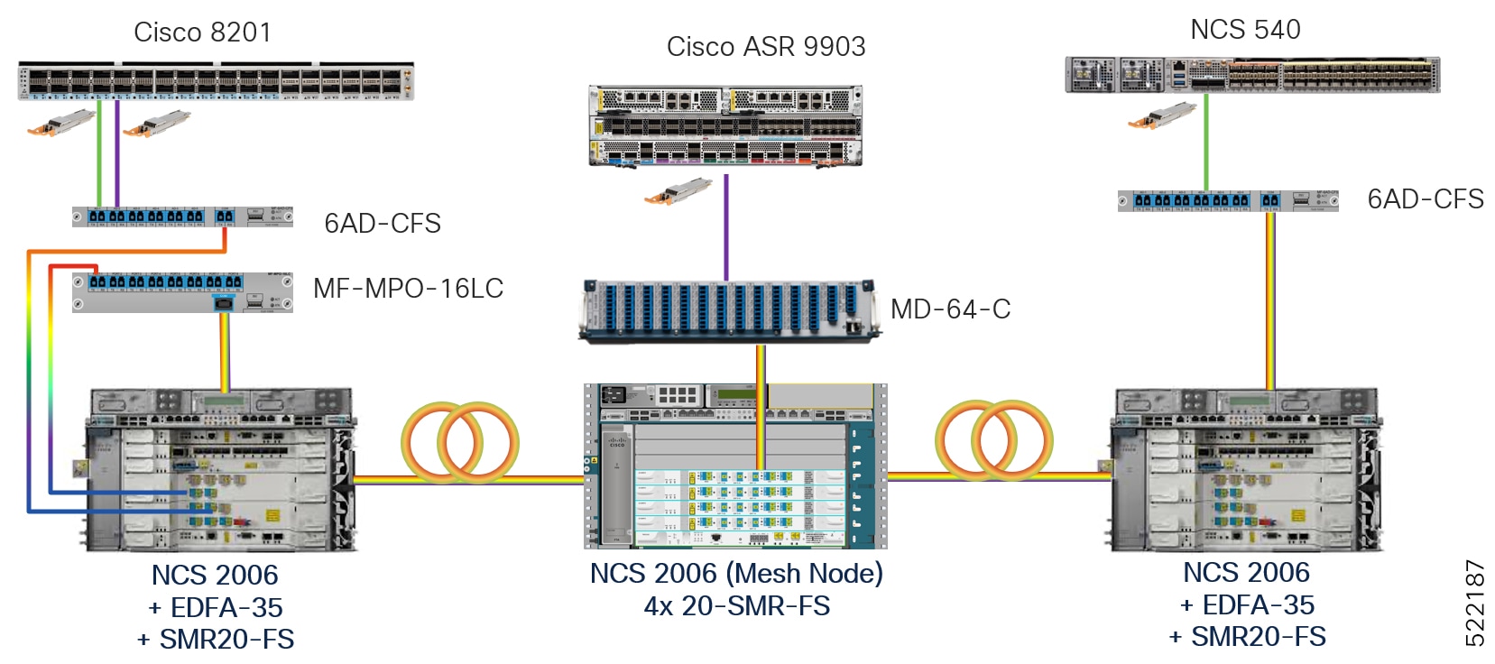
This topology diagram illustrates the setup for mesh networks.
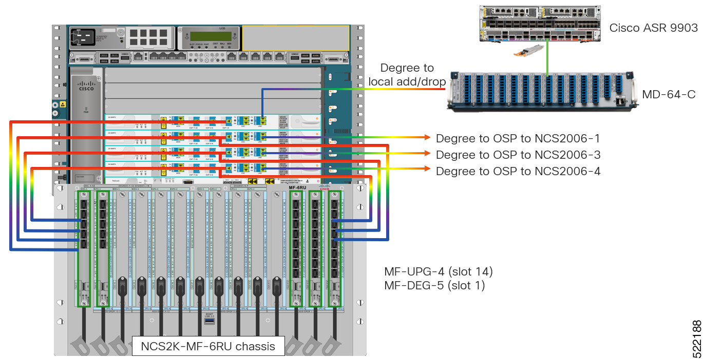
This figure shows the NCS 2006 mesh node in detail with mesh panels.
This diagram shows the wiring diagram for the mesh topology.
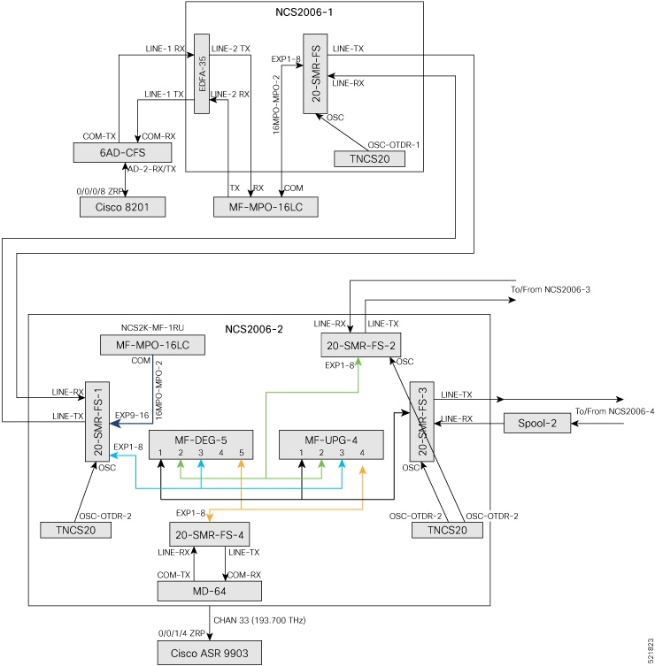
In this sample topology, Cisco 8201 is the source router and Cisco ASR 9903 is the destination router, using a four-degree node. Nodes with fewer or more degrees are also supported. NCS2006-2 is a four-degree mesh node that drops a colored wavelength on the Cisco ASR 9903 router. The MD-64 unit is used as a fixed channel muxponder but other options can also be connected to the 20-SMR-FS card. The other degrees are connected to NCS 2000 nodes in the network.
Topology components
You need this hardware to build this topology:
-
Cisco 8200 series routers
-
Cisco ASR 9903 routers
-
NCS1K-MD-64-C modules
-
6-AD-CFS units
-
MF-DEG-5 units
-
MF-UPG-4 units
-
MF-MPO-16LC units
-
Cisco NCS 2006 shelves
-
TNCS-2O, OPT-EDFA-35, and 20-SMR-FS cards
-
QDD-400G-ZR-S transceiver modules
-
LC/LC cables
-
16MPO-MPO-2 cables
-
ONS-MPO16-2x8-2 cables
For more information, see Hardware components.
Port connections
Use this sequence to connect the cables and build this topology:
-
On the Cisco 8201 router:
-
Align the QDD-400G-ZR-S transceiver module in front of the transceiver socket in port 4. Then, carefully slide the transceiver into the socket until the transceiver comes in contact with the socket electrical connector.
-
Holding the pull-tab, seat the transceiver in the transceiver socket of the module fully until it clicks.
-
Attach an LC/LC fiber to the QDD-400G-ZR-S transceiver module immediately.
-
Connect the LC/LC fiber's other end to the matching bulkhead adapter on the 6AD-CFS module's front panel. (AD-2 RX/TX port). In this sample topology, we use channel ID 33, which corresponds to a frequency of 193.700 THz.
-
-
Connect an LC/LC fiber from the COM-RX port of the 6AD-CFS module to the LINE-1-TX port of the EDFA 35 amplifier card in NCS 2006-1.
-
Connect an LC/LC fiber from the COM-TX port of the 6AD-CFS module to the LINE-1-RX port of the EDFA 35 amplifier card in NCS 2006-1.
-
Connect an LC/LC fiber from the LINE-2-RX port of the EDFA-35 card in NCS 2006 -1 to the TX port of the MF-MPO-16LC unit.
-
Connect an LC/LC fiber from the LINE-2-TX port of the EDFA-35 card in NCS 2006 -1 to the RX port of the MF-MPO-16LC unit.
-
Connect an 16MPO-MPO-2 fiber from the EXP1-8 port of the 20-SMR-FS card in NCS 2006 -1 to the COM port of the MF-MPO-16LC unit.
-
Connect an LC/LC fiber from the OSC-OTDR-2 port on the TNCS-2O card to the OSC port on the 20-SMR-FS card in NCS 2006 -1.
-
Connect an LC/LC fiber from the LINE-TX port of the 20-SMR-FS card in NCS 2006 -1 to the LINE-RX port of the 20-SMR-FS-1 card in NCS 2006 -2.
-
Connect an LC/LC fiber from the LINE-RX port of the 20-SMR-FS card in NCS 2006 -1 to the LINE-TX port of the 20-SMR-FS-1 card in NCS 2006 -2.
-
Connect an LC/LC fiber from the OSC-OTDR-2 port on the TNCS-2O card to the OSC port on the 20-SMR-FS-1 card in NCS 2006-2.
-
Connect an 16MPO-MPO-2 fiber from the EXP9-16 port of the 20-SMR-FS-1 card in NCS 2006 -2 to the COM port of the MF-MPO-16LC unit.
-
Connect one end of the ONS-MPO16-2x8-2 cable to the EXP1-8 port of the 20-SMR-FS-1 card in NCS 2006 -2. Connect the other two ends to port 3 of the MF-DEG-5 unit and MF-UPG-4 unit respectively.
-
Connect one end of the ONS-MPO16-2x8-2 cable to the EXP1-8 port of the 20-SMR-FS-2 card in NCS 2006 -2. Connect the other two ends to port 2 of the MF-DEG-5 unit and MF-UPG-4 unit respectively.
-
Connect one end of the ONS-MPO16-2x8-2 cable to the EXP1-8 port of the 20-SMR-FS-3 card in NCS 2006 -2. Connect the other two ends to port 1 of the MF-DEG-5 unit and MF-UPG-4 unit respectively.
-
Connect one end of the ONS-MPO16-2x8-2 cable to the EXP1-8 port of the 20-SMR-FS-4 card in NCS 2006 -2. Connect the other end to port 5 of the MF-DEG-5 unit only.
-
Connect an LC/LC fiber from the OSC-OTDR-2 port on the TNCS-2O card to the OSC port on the 20-SMR-FS-2 card in NCS 2006-2.
-
Connect an LC/LC fiber from the OSC-OTDR-2 port on the TNCS-2O card to the OSC port on the 20-SMR-FS-3 card in NCS 2006-2.
-
Connect LC/LC fibers from the LINE-TX and LINE-RX ports of the 20-SMR-FS-2 card in NCS 2006-2 to the ports of NCS2006-3.
-
Connect LC/LC fibers from the LINE-TX and LINE-RX ports of the 20-SMR-FS-3 card in NCS 2006-2 to the ports of NCS2006-4.
-
Connect an LC/LC fiber from the LINE-RX port on the 20-SMR-FS-4 card in NCS 2006-2 to the COM-TX port of the MD-64 unit.
-
Connect an LC/LC fiber from the LINE-TX port on the 20-SMR-FS-4 card in NCS 2006-2 to the COM-RX port of the MD-64 unit.
-
Connect one end of the LC/LC fiber to the corresponding bulkhead adapter on the front panel of the NCS1K-MD-64-C (MD-64-1) module. Connect the other end of the fiber to the QDD-400G-ZR-S transceiver module installed in port 4 of the ASR 9903 router.
Next steps
After you build the topology, perform these steps: