Overview
This section explains how to build a multi-degree Routed Optical Networking topology using Cisco NCS 1010 nodes. It describes the topology layout, wiring approach, required modules, and configuration tasks for multi-degree optical connectivity.
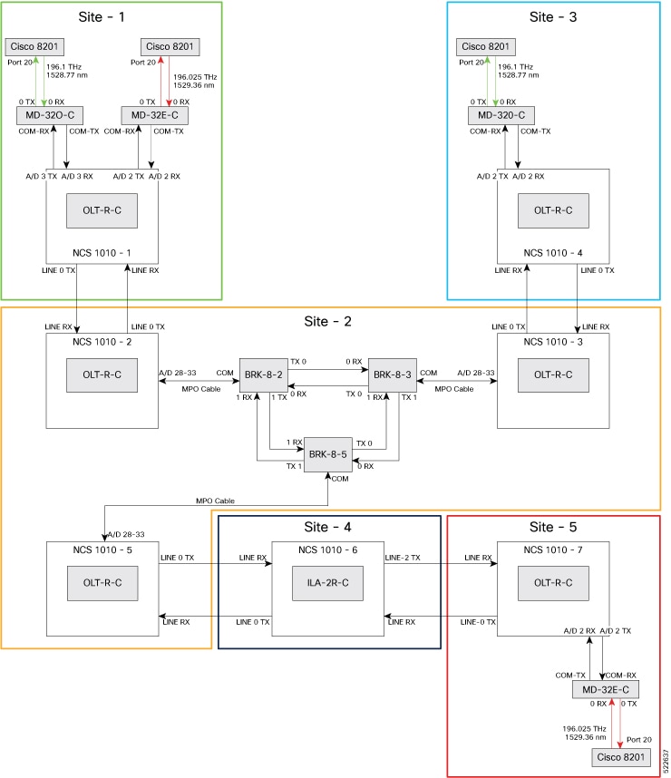
Topology diagram
This topology diagram illustrates the setup for multi-degree networks using NCS 1010 nodes.
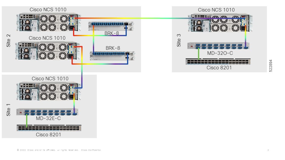
These diagrams show the wiring configuration for the multi-degree topology using NCS 1010 nodes.
Topology components
You need this hardware to build this topology:
-
Cisco NCS 1010 devices
-
NCS1K-MD32E-C modules
-
NCS1K-MD32O-C modules
-
NCS1K-BRK-8 modules
-
Cisco 8201 routers
-
QDD-400G-ZR-S transceivers
-
LC/LC cables
-
MPO cables
For more information, see Hardware components.
Use this sequence to connect the cables and build this topology:
-
On the Cisco 8201 routers:
-
Align the QDD-400G-ZR-S transceiver module with the transceiver socket opening in Port 20. Carefully slide it into the socket until contact with the socket electrical connector.
-
Holding the pull-tab, seat the transceiver in the module’s transceiver socket fully until it clicks.
-
Attach an LC/LC fiber immediately to the QDD-400G-ZR-S transceiver module.
-
Connect the other end of the LC/LC fiber to the corresponding bulkhead adapter on the front panel of the NCS1K-MD-32O-C (MD-32-O-C using frequency 196.1 THz) module or the NCS1K-MD-32E-C (MD-32-E-C using frequency 195.025 THz) module.
-
-
Connect an LC/LC fiber from the COM-TX port of the MD-32-O-C module to the A/D 3 RX port of the OLT-R-C module in NCS 1010–1.
-
Connect an LC/LC fiber from the COM-RX port of the MD-32-O-C module to the A/D 3 TX port of the OLT-R-C module in NCS 1010–1.
-
Connect an LC/LC fiber from the COM-TX port of the MD-32-E-C module to the A/D 2 RX port of the OLT-R-C module in NCS 1010–1.
-
Connect an LC/LC fiber from the COM-RX port of the MD-32-E-C module to the A/D 2 TX port of the OLT-R-C module in NCS 1010–1.
-
Connect an LC/LC fiber from the LINE RX port of the OLT-R-C module in NCS 1010–1 to the LINE 0 TX port of the OLT-R-C module in NCS 1010–2.
-
Connect an LC/LC fiber from the LINE 0 TX port of the OLT-R-C module in NCS 1010–1 to the LINE RX port of the OLT-R-C module in NCS 1010–2.
-
Connect an MPO fiber from the A/D 4–11 port of the OLT-R-C module in NCS 1010–2 to the COM port of the BRK-8-2 module.
-
Using LC/LC fibers, interconnect the BRK-8-2, BRK-8-3, and BRK-8-5 modules.
-
Connect an MPO fiber from the COM port of the BRK-8-3 module to the A/D 4–11 port of the OLT-R-C module in NCS 1010–3 .
-
Connect an LC/LC fiber from the LINE RX port of the OLT-R-C module in NCS 1010–3 to the LINE 0 TX port of the OLT-R-C module in NCS 1010–4.
-
Connect an LC/LC fiber from the LINE 0 TX port of the OLT-R-C module in NCS 1010–3 to the LINE RX port of the OLT-R-C module in NCS 1010–4.
-
Connect an LC/LC fiber from the COM-TX port of the MD-32-O-C module to the A/D 2 RX port of the OLT-R-C module in NCS 1010–4.
-
Connect an LC/LC fiber from the COM-RX port of the MD-32-O-C module to the A/D 2 TX port of the OLT-R-C module in NCS 1010–4.
-
Connect an MPO fiber from the COM port of the BRK-8-5 module to the A/D 4–11 port of the OLT-R-C module in NCS 1010–5 .
-
Connect an LC/LC fiber from the LINE 0 TX port of the OLT-R-C module in NCS 1010–5 to the LINE 0 LINE RX port of the ILA-2R-C module in NCS 1010–6.
-
Connect an LC/LC fiber from the LINE RX port of the OLT-R-C module in NCS 1010–5 to the LINE 0 TX port of the ILA-2R-C module in NCS 1010–6.
-
Connect an LC/LC fiber from the LINE-2 TX port of the ILA-2R-C module in NCS 1010–6 to the LINE RX port of the OLT-R-C module in NCS 1010–7.
-
Connect an LC/LC fiber from the LINE 2 LINE RX port of the ILA-2R-C module in NCS 1010–6 to the LINE 0 TX port of the OLT-R-C module in NCS 1010–7.
-
Connect an LC/LC fiber from the COM-TX port of the MD-32-E-C module to the A/D 2 RX port of the OLT-R-C module in NCS 1010–7.
-
Connect an LC/LC fiber from the COM-RX port of the MD-32-E-C module to the A/D 2 TX port of the OLT-R-C module in NCS 1010–7.
Next steps
After you build the topology, perform these steps: