Enter the show frequency synchronization selection command to verify that PLE-PE2 is locked to the clock of PLE-PE1.
You have synchronized the clocks between PE1 and PE2 routers.
Configure optics controller with payloads
Use this task to configure the optics controller to support various payload types.
Each port on the NC55-OIP-2 (PID of PLE Modular Port Adapter) can be configured independently for a specific PLE transport type. Use the port-mode command under the optics controller to perform this configuration.
For more information about all the supported payloads, see the Private Line Emulation section.
Procedure
1.
Enter these commands to configure the optics controller with Ethernet payload.
Enter these commands to configure the optics controller with Fiber Channel payload.
Example:
Router(config)# controller Optics0/0/3/5
Router(config-Optics)# port-mode FC framing cem-packetize rate FC1
The optics controller is configured with different payloads.
Configure a QoS policy
Use this task to configure a QoS policy that prioritizes PLE traffic. QoS policy configuration is recommended to prevent high-priority PLE traffic from being dropped during network congestion.
Procedure
1.
Enter the policy-map ple-policy command to define the parent QoS policy to be applied to the CEM interface to prioritize the PLE traffic.
Example:
Router(config)# policy-map ple-policy
2.
Enter the class class-default command to specify the default class.
Example:
Router(config)# class class-default
A PLE service has only one traffic flow type. Therefore, the default class is used to match all the ingress packets on the PLE CEM interface.
3.
Enter the set traffic-classtraffic-class-number command to specify the traffic class.
Example:
Router(config)# set traffic-class 6
Cisco NCS 5500 and NCS 5700 platforms use the traffic class to identify specific traffic flows within the router and to determine egress treatment. In this example, ingress traffic is set to traffic class 6. The egress QoS policy matches traffic class 6 to set the appropriate queuing behavior. This value is used as an example; it must be set to the high priority EXP value used across the network. The egress QoS policy is outside the scope of this guide. For details, see Modular QoS Configuration Guide for Cisco NCS 5500 Series Routers.
4.
Enter the set mpls experimental topmostmpls-exp-value command to set the topmost MPLS EXP (TC) value.
Example:
Router(config)# set mpls experimental topmost 6
The MPLS EXP (TC) value can be used at subsequent nodes in the path to classify PLE traffic and set appropriate queuing behavior. This value is used as an example; it must be set to the high priority EXP value used across the network.
You have configured the QoS policy.
Configure CEM interface for L2VPN service
Use this task to configure the CEM interface for the L2VPN EVPN-VPWS service.
Procedure
1.
Enter the interface CEM command to configure the appropriate CEM interface.
Example:
Router(config)# interface CEM0/0/3/1
2.
Enter the l2transport command to enable the CEM interface to be used in a L2VPN EVPN-VPWS service.
Example:
Router(config-if)# l2transport
Configure performance measurement
Use this task to configure performance measurement for enabling liveness monitoring of the Segment Routing policy.
Procedure
1.
Enter the performance-measurement command to enter the performance measurement configuration mode.
Example:
Router(config)# performance-measurement
2.
Enter the liveness-profile name liveness-check command to create a SR Policy liveness profile.
Example:
Router(config-perf-meas)# liveness-profile name liveness-check
3.
Enter the liveness-detection multipliermultiplier-value command to configure liveness detection parameters. This command sets the number of missed liveness probes to determine whether the SR Policy is down.
Enter the probe command to enter the probe parameter configuration mode.
Example:
Router(config-pm-ld-srpolicy)# probe
Note
The probe measurement mode is set to loopback by default. In this mode, the probe packets from the sender node are looped back to the sender node to test end-to-end liveness.
5.
Enter the tx-intervalinterval-value command to set the interval of probe packets that are sent by the sender.
The interval value is set in microseconds. In this example, it is set to 30 seconds.
Note
Using a tx-interval value lower than 30 seconds requires hw-offload support. NCS-55A2-MOD supports this in R7.9.1.
6.
Enter the tos dscpdscp-value command to set the Differentiated Services Code Point (DSCP) value on the probe packets to the specified DSCP.
Example:
Router(config-pm-ld-srpolicy-probe)# tos dscp 48
In this example, the DSCP value is 48. You must set the DSCP value to the appropriate QoS setting on the provider network so that the liveness probe packets are treated as high priority.
Performance measurement and liveness monitoring are enabled for the Segment Routing policy.
Configure segment routing adjacency SIDs
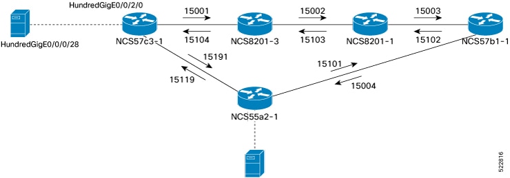
Adjacency SIDs are unidirectional. They define the explicit path between endpoints. Configure adjacency SIDs on each interface that participates in the SR policy path.
This figure shows the SR adjacency SIDs configured between routers.
Figure 1. Segment routing adjacency SIDs
Use this task to configure segment routing adjacency Segment Identifiers (SIDs), enabling precise control over packet forwarding paths at the link level within a segment routing-enabled network.
Procedure
1.
Enter the router isis command to enter the IS-IS configuration mode for the appropriate instance.
Example:
Router(config)# router isis core
2.
Enter the interface controller-type rack/slot/instance/port command to configure the specific IS-IS interface.
Example:
Router(config-isis)# interface HundredGigE0/0/2/0
3.
Enter the address-family ipv4 unicast command to enter the IPv4 address family configuration if MPLS segment routing is used.
Example:
Router(config-isis)# address-family ipv4 unicast
4.
Enter the adjacency-sid absoluteadjacency-sid-value command to configure a persistent SR adjacency SID on the interface.
The adjacency SID value must be assigned from the Segment Routing Local Block (SRLB) of the router. The default SRLB range in IOS XR is 15,000 to 15,999. Configure other SR adjacency SIDs as appropriate.
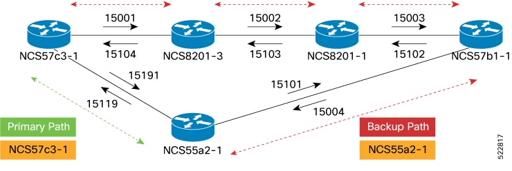
Define paths between PLE endpoints
Use this task to define network paths between PLE endpoints, enabling reliable and optimized connectivity for PLE services.
Note
Use this task only with static circuit-style SR-TE policies.
Figure 2. Working and reverse path definitions
Configure the NCS57C3-1 router to set the working forward path according to the illustration. The working forward path is a single hop between directly connected routers.
Procedure
1.
Enter the segment-routing command to enter segment routing configuration mode.
Example:
Router(config)# segment-routing
2.
Enter the traffic-engineering command to enter segment routing TE configuration.
Example:
Router(config-sr)# traffic-engineering
3.
Enter the segment-list working-forward-path command to create segment list named working-forward-path.
Enter the index command to set the index to the first hop interface adjacency SID.
Example:
Router(config-sr-te-sl)# index 1 mpls label 15191
The working and protection paths are defined for the selected PLE endpoints.
Example
Configure the NCS57C3-1 router to define all the paths between PLE endpoints according to the illustration. The working forward path is a single hop between directly connected routers. The working reverse path is a single hop between directly connected routers. The protect forward path has four interface hops between the near-end and far-end router. The protect reverse path has four interface hops between the near-end and far-end router.
Router(config)# segment-routing

Router(config-sr)# traffic-engineering
Router(config-sr-te)# segment-list working-forward-path
Router(config-sr-te-sl)# index 1 mpls label 15191
!
Router(config-sr-te)# segment-list working-reverse-path

Router(config-sr-te-sl)# index 1 mpls label 15119
!
Router(config-sr-te)# segment-list protect-forward-path
Router(config-sr-te-sl)# index 1 mpls label 15001
Router(config-sr-te-sl)# index 2 mpls label 15002
Router(config-sr-te-sl)# index 3 mpls label 15003
Router(config-sr-te-sl)# index 4 mpls label 15004
!
Router(config-sr-te)# segment-list protect-reversepath
Router(config-sr-te-sl)# index 1 mpls label 15101
Router(config-sr-te-sl)# index 2 mpls label 15102
Router(config-sr-te-sl)# index 3 mpls label 15103
Router(config-sr-te-sl)# index 4 mpls label 15104
Configure the NCS55A2-1 router to define all the paths between PLE endpoints according to the illustration.
Router(config)# segment-routing

Router(config-sr)# traffic-engineering
Router(config-sr-te)# segment-list working-forward-path
Router(config-sr-te-sl)# index 1 mpls label 15119
!
Router(config-sr-te)# segment-list working-reverse-path
Router(config-sr-te-sl)# index 1 mpls label 15191
!
Router(config-sr-te)# segment-list protect-forward-path
Router(config-sr-te-sl)# index 1 mpls label 15101
Router(config-sr-te-sl)# index 2 mpls label 15102
Router(config-sr-te-sl)# index 3 mpls label 15103
Router(config-sr-te-sl)# index 4 mpls label 15104
!
Router(config-sr-te)# segment-list protect-reversepath
Router(config-sr-te-sl)# index 1 mpls label 15001
Router(config-sr-te-sl)# index 2 mpls label 15002
Router(config-sr-te-sl)# index 3 mpls label 15003
Router(config-sr-te-sl)# index 4 mpls label 15004
Configure static circuit-style SR-TE policies
Use this task to configure static circuit-style Segment Routing Traffic Engineering (SR-TE) policies, enabling predefined and predictable traffic paths within the network.
Enter the policypolicy-name command to create a SR-TE policy.
Example:
Router(config-sr-te)# policy to-55a2-1
3.
Enter the colorcolorend-point ipv4loopback-address command to configure the SR-TE policy with the user-defined color and loopback address of the remote PLE far-end router.
Example:
Router(config-sr-te-policy)# color 1001 end-point ipv4 10.0.0.44
4.
Enter the path-protection command to enable path protection on the SR-TE policy.
Example:
Router(config-sr-te-policy)# path-protection
When path protection is configured, the near-end router keeps the protect path in a warm standby state. This allows it to quickly transition to the protect path if the working path is down.
5.
Enter the candidate-paths command to configure the SR working and protect candidate paths.
Example:
Router(config-sr-te-policy)# candidate-paths
6.
Enter the preferencepreference-value command to set the user-defined preference on the protect path.
Example:
Router(config-sr-te-policy-path)# preference 50
Paths with higher preference values are chosen over those with lower preference values.
Note
You must always set the protect path with a lower preference value.
7.
Enter the explicit segment-list command to configure the candidate path to use an explicit segment list.
Configure dynamic circuit-style SR-TE policies without bandwidth CAC
Use this task to configure dynamic circuit-style Segment Routing Traffic Engineering (SR-TE) policies without enabling bandwidth Call Admission Control (CAC), allowing for flexible path selection without bandwidth reservation constraints.
Before you begin
Dynamic circuit-style SR-TE policies without bandwidth CAC require this software:
IOS XR R7.8.1 or later
SR-PCE 7.8.1 or later
Procedure
1.
Enter the segment routing traffic engineering configuration mode.
Enter the policypolicy-name command to create a SR-TE policy.
Example:
Router(config-sr-te)# policy to-55a2-1
3.
Enter the colorcolorend-point ipv4loopback-address command to configure the SR-TE policy with the user-defined color and loopback address of the remote PLE far-end router.
Example:
Router(config-sr-te-policy)# color 119 end-point ipv4 10.0.0.44
4.
Enter the path-protection command to enable path protection on the SR-TE policy.
Example:
Router(config-sr-te-policy)# path-protection
When path protection is configured, the near-end router keeps the protect path in a warm standby state. This allows it to quickly transition to the protect path if the working path is down.
5.
Enter the candidate-paths dynamic pcep command to configure the SR working, protect, and restoration candidate paths.
The candidate-paths parameter is set to dynamic->pcep to enable SR-PCE delegation. The dynamic computation uses standard metrics, including traffic engineering, IGP, and latency.
6.
Enter the preferencepreference-value command to set the user-defined preference on the protect path.
Example:
Router(config-sr-te-policy-path)# preference 50
Paths with higher preference values are chosen over those with lower preference values.
Note
You must always set the protect path with a lower preference value.
A third candidate path with a preference lower than 100 can be defined as a restoration path. This path is not pre-signaled and must be configured with backup-ineligible. While the restoration path does not have a disjoint-path ID, it uses a bidirectional association ID that matches the reverse policy.
The lock-duration parameter determines the reversion behavior. When a higher-preference path becomes available, the policy switches to it after the lock-duration expires. By default, the lock-duration is set to 300 seconds. Setting the value to 0 disables dynamic reversion.
7.
Enter the constraints segments protection command to configure the protection behavior constraints of adjacency SID.
Circuit-style uses the segments constraints of unprotected-only and adjacency-sid-only. If manual adjacency-SIDs are configured, they are used; otherwise, dynamic adjacency-SIDs are used. It is recommended to configure manual adjacency-SIDs.
8.
Enter the disjoint-path group-id 10 type {link | node | srlg | srlg-node} command to configure the disjoint-path constraints.
The group-id for the disjoint-path must be identical on both the active and backup paths. Additionally, the group-id must be unique among nodes that use the same SR-PCE
The co-routed association ID must be the same for both bidirectional active and backup paths.
9.
Configure a user-defined liveness policy.
Example:
Router(config)# performance-measurement
Router(config-perf-meas)# liveness-detection
Router(config-perf-meas)# liveness-profile name liveness-check
The policy uses the previously defined liveness profile named liveness-check.
This example configures the dynamic circuit-style SR-TE policy without bandwidth CAC.
policy dynamic-cs-srte-to-55a2-p2
   color 119 end-point ipv4 10.0.0.44
   path-protection
   !
   candidate-paths
    preference 100
     dynamic
      pcep
      !
      metric
       type igp
      !
     !
     constraints
      segments
       protection unprotected-only
       adjacency-sid-only
      !
      disjoint-path group-id 10 type link
     !
     bidirectional
      co-routed
      association-id 101
     !
    !
    preference 200
     dynamic
      pcep
      !
      metric
       type igp
      !
     !
     lock
       duration 30
     !
     constraints
      segments
       protection unprotected-only
       adjacency-sid-only
      !
      disjoint-path group-id 10 type link
     !
     bidirectional
      co-routed
      association-id 201
     !
    !
    preference 50
     dynamic
      pcep
      !
      metric
       type igp
      !
     !
     backup-ineligible
     lock
       duration 60
     !
     constraints
      segments
       protection unprotected-only
       adjacency-sid-only
      !
     !
     bidirectional
      co-routed
      association-id 301
     !
    !
   !
   performance-measurement
    liveness-detection
     liveness-profile backup name CS-PROTECT
     liveness-profile name CS-WORKING
     invalidation-action down
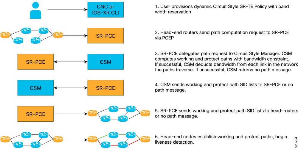
Configure dynamic circuit-style SR-TE policies with bandwidth CAC
Use this task to configure dynamic circuit-style SR-TE policies with bandwidth Call Admission Control (CAC).
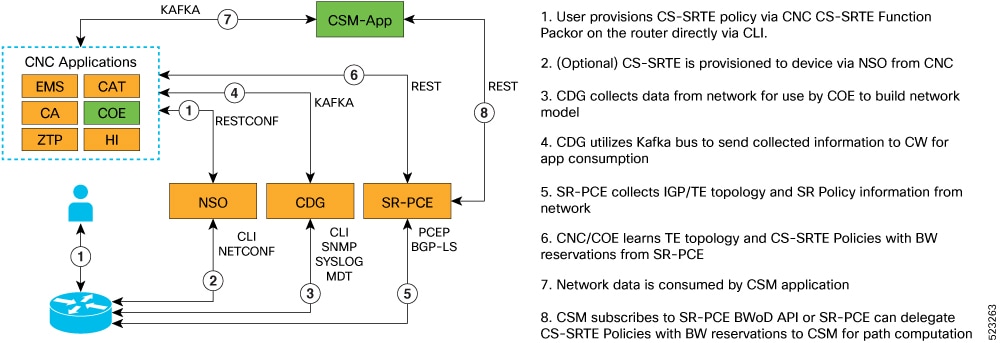
Dynamic PLE with bandwidth CAC is supported through Crosswork Network Controller. The bandwidth constraint is specified for the circuit-style policy. The Cisco Crosswork Optimization Engine application is included in Circuit Style Manager.
The circuit-style Segment Routing Traffic Engineering (CS SR-TE) feature pack provides a bandwidth-aware Path Computation Element (PCE) to compute CS SR-TE policy paths that you can visualize in your network. CS SR-TE policies guarantee allocated bandwidth services with predictable latency and persistent bidirectional path protection of critical traffic. CS SR-TE reserves a percentage of bandwidth in the network and computes bidirectional failover paths for CS SR-TE policies using the requested bandwidth.
Circuit Style Manager requires you to configure policies on each head-end node using matching association IDs, bandwidth values, constraints, computation type, and source and endpoint IP addresses.
Verify that the CS SR-TE policies appear in the SR Policy table.
Enable circuit-style SR-TE using Crosswork Network Controller
Use this task to enable circuit-style Segment Routing Traffic Engineering (CS SR-TE) policies using Cisco Crosswork Network Controller.
To manage and visualize CS-SR policies on the topology map, you must first enable CS SR-TE and set the bandwidth reservation settings.
When CS SR-TE is enabled, it computes the best failover bidirectional paths between the two nodes, using the requested bandwidth and other constraints defined in the CS SR-TE policy configuration.
Procedure
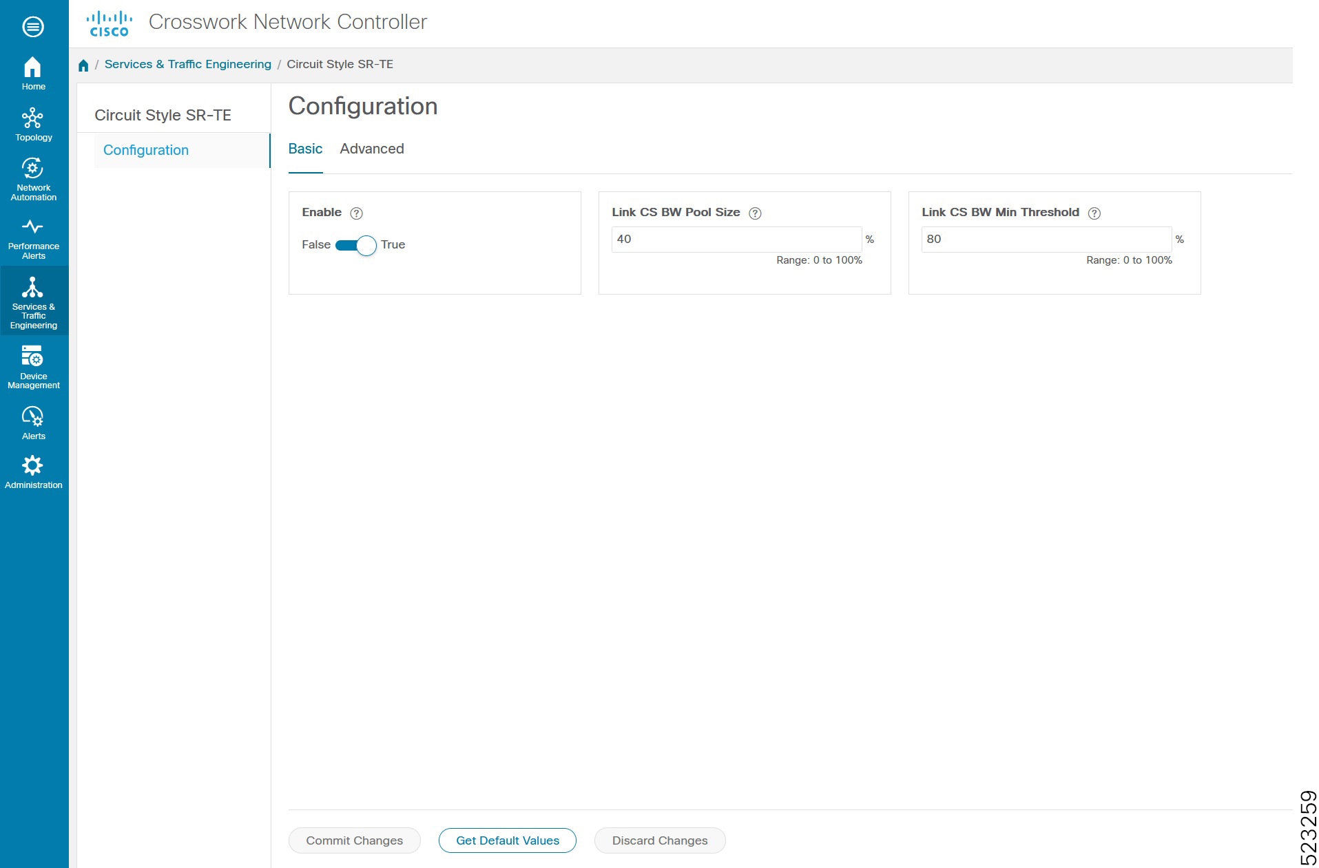
1.
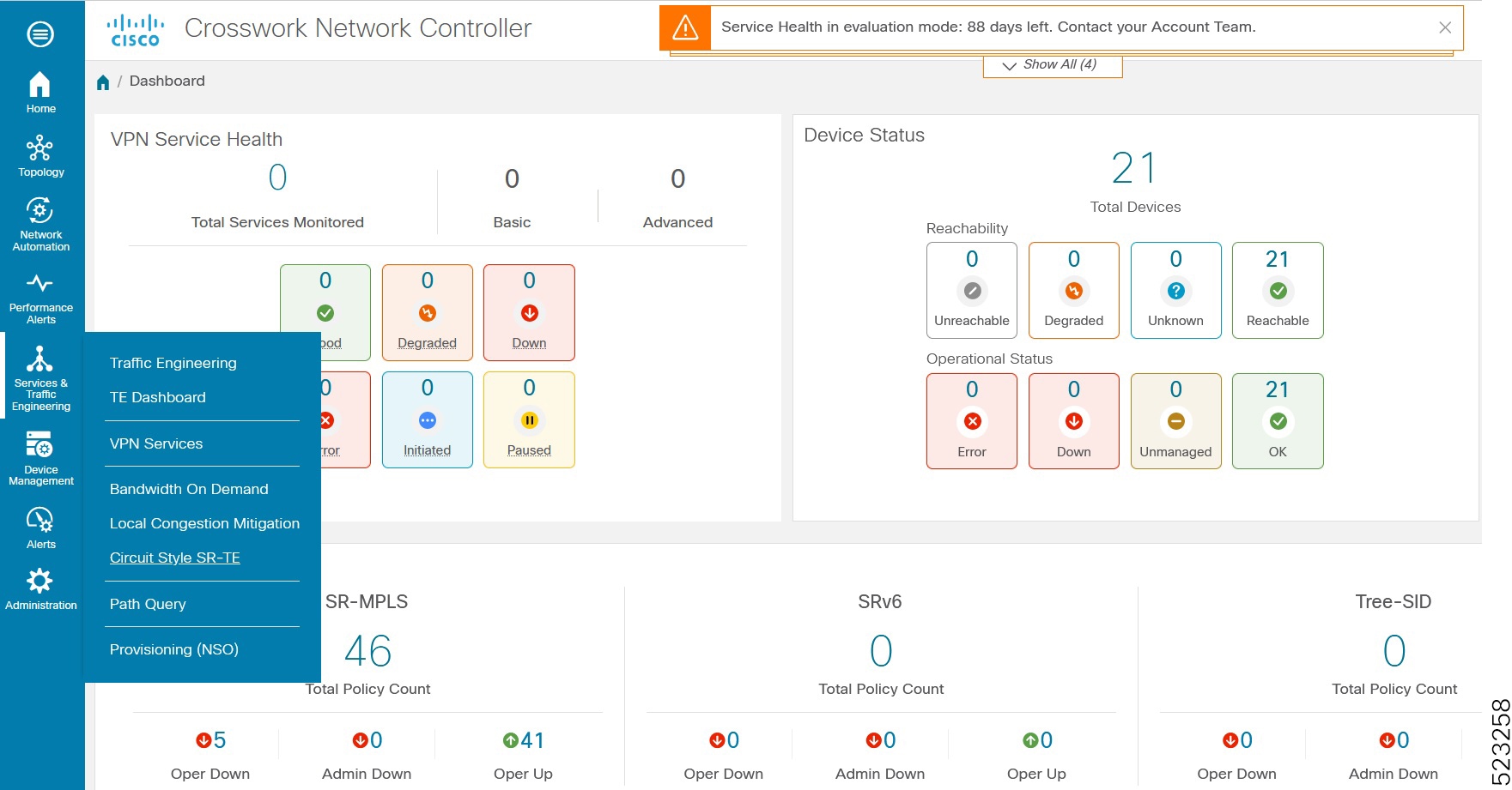
From the main menu, choose Services & Traffic Engineering > Circuit Style SR-TE > Configuration .
2.
Toggle the Enable switch to True.
3.
Enter the required bandwidth pool size and the threshold information.
Option
Description
Basic Pane
Link CS BW Pool Size
The percentage of bandwidth that each link reserves for CS-SR policies.
Link CS BW Min Threshold
An alert is generated when the bandwidth utilization percentage on a link used for a CS-SR policy exceeds this value.
Advanced Pane
Validation Interval
The interval that CS-SR policy will wait before the bandwidth that is reserved for an undelegated policy is returned to the CS-SR policy bandwidth pool.
Timeout
The duration until which CS-SR policy will wait for the delegation request, to generate a notification.
Restore Delegation Delay
The duration until which CS-SR policy will pause before processing a restore path delegation.
4.
Click Commit Changes to save the configuration.
View circuit-style SR-TE policy details using Crosswork Network Controller
Use this task to view details about circuit-style Segment Routing Traffic Engineering (CS SR-TE) policies using Cisco Crosswork Network Controller.
Procedure
1.
From the main menu, choose Services & Traffic Engineering > SR-MPLS and click Circuit Style.
The SR Policy table lists all the CS SR-TE policies.
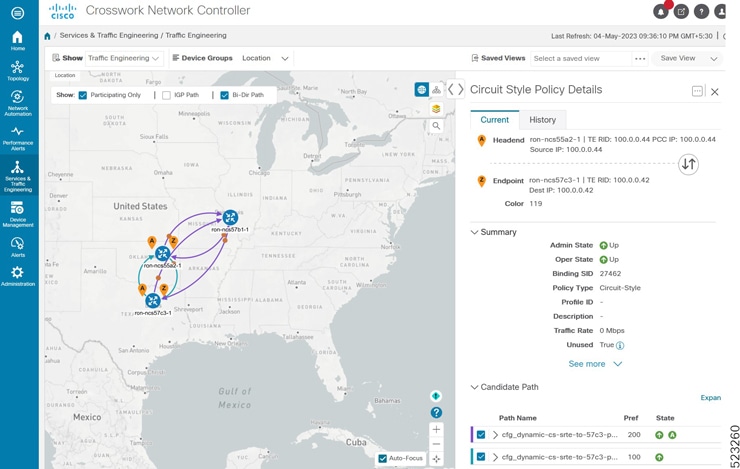
2.
From the Actions column, click View Details for one of the CS SR-TE policies.
The Circuit Style Policy Details window is displayed in the side panel. By default, the active path is displayed and shows the bidirectional paths (Bi-Dir Path checkbox is selected) on the topology map.
If the bandwidth of a new policy exceeds bandwidth pool size, the policy goes down. The requested bandwidth is set to the configured bandwidth, but the reserved bandwidth becomes zero.
If an existing policy is configured with a bandwidth that exceeds the bandwidth pool size, the policy remains up, but the reserved bandwidth stays at its previous value.
The sample output displays a policy's requested bandwidth and current bandwidth.
Use this task to configure PLE over Ethernet VPN Virtual Private Wire Service (EVPN-VPWS), enabling the delivery of emulated private line services.
The two core components are the Pseudowire class, which specifies the transport type, and the xconnect service, which configures the EVPN-VPWS service parameters.
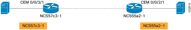
Figure 6. PLE EVPN-VPWS service
Configure the NCS57C3-1 router.
Procedure
1.
Enter the l2vpn command to enter l2vpn configuration mode.
Example:
Router(config)# l2vpn
2.
Enter the pw-classuser-defined-name command to define the Pseudowire class used with the PLE service.
Example:
Router(config-l2vpn)# pw-class circuit-style-srte
The same Pseudowire class can be used for multiple PLE services between the same far-end routers, or a unique class can be used for each service. The Pseudowire class defines the underlying transport for the service. In this case, the transport is MPLS, using a specific SR-TE policy. The pw-class command is followed by a user-defined name. In this example, the name is circuit-style-srte.
3.
Enter the encapsulation mpls command to configure transport encapsulation.
Example:
Router(config-l2vpn-pwc)# encapsulation mpls
4.
Enter the preferred-path sr-te policy command to configure an explicit MPLS path to be used for the L2VPN service.
The preferred-path is the circuit-style policy used to configure an explicit MPLS path for the L2VPN service. In this case, the preferred-path is set to the SR-TE policy created from the source node to the 10.0.0.42 endpoint node. The path refers to the computed name of the policy, not the configured name.
5.
Enter the xconnect group ple command to enter xconnect configuration mode.
Example:
Router(config-l2vpn)# xconnect group ple
The xconnect group command is used to administratively group similar L2VPN services and can be set to any user-defined value.
6.
Enter the p2puser-defined-name command to create point-to-point L2VPN service with user-defined name ple-cs-1.
Example:
Router(config-l2vpn-xc)# p2p ple-cs-1
7.
Enter the interface cem command to specify the client interface.
Example:
Router(config-l2vpn-xc-p2p)# interface cem 0/0/2/1
This interface is the CEM interface type for PLE.
8.
Enter the neighbor evpn command to configure EVPN-VPWS parameters.
Example:
Router(config-l2vpn-xc-p2p)# neighbor evpn evi 100 target 4201 source 4401
The user-defined evi value must be the same on each far-end router. The target must match the source value configured on the remote endpoint.
9.
Enter the pw-class command to attach the previously defined Pseudowire class circuit-style-te to the L2VPN service.