Overview
This section explains the components and connections used in long-haul Routed Optical Networking designs. It describes terminal, ILA, OLA, and DGE node roles, wiring requirements, and optical considerations for spans beyond metro reach.
Topology diagram
This topology diagram illustrates the setup for long haul networks.
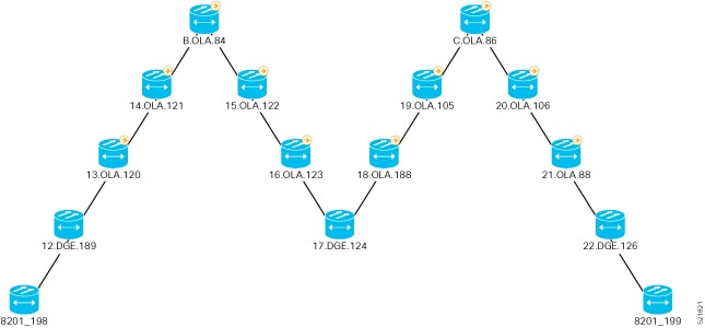
This topology uses several types of nodes, including ILA, terminal, OLA, and DGE nodes. The ILA nodes span from 80 to 120 km. The DGE nodes allow gain equalization in long haul networks over 1200 km. This topology uses terminal, OLA, and DGE nodes.
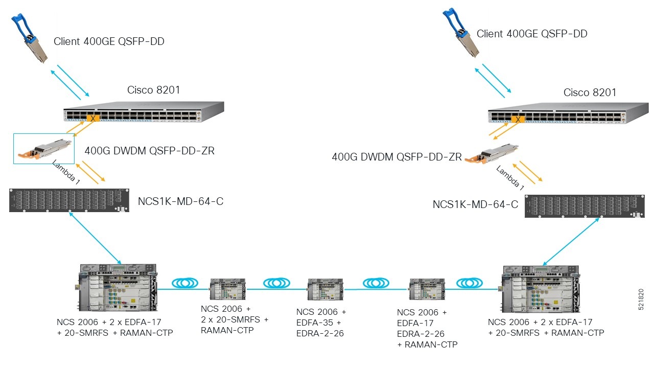
These diagrams show the wiring configuration for the long haul topology.
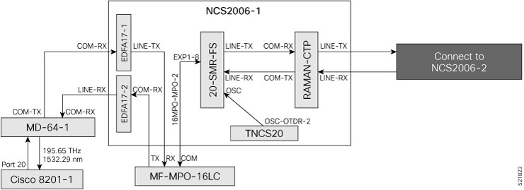
In this sample topology, Cisco 8201–1 is the source router, and Cisco 8201–2 is the destination router.
Topology components
You need this hardware to build this topology:
-
Cisco 8200 Series routers
-
NCS1K-MD-64-C modules
-
Cisco NCS 2006 shelves
-
TNCS-2O, OPT-EDFA-17, EDRA-2-26, RAMAN-CTP, and SMR20 FScards
-
MF-MPO-16LC passive modules (seated in an NCS2K-MF-1RU mechanical frame)
-
QDD-400G-ZR-S transceiver
-
LC/LC cables
-
16MPO-MPO-2 cables
For more information, see Hardware components.
Port connections
Use this sequence to connect the cables and build this topology:
-
On the Cisco 8201–1 and Cisco 8201–2 routers:
-
Align the QDD-400G-ZR-S transceiver module with the transceiver socket opening in Port 20. Then, slide the transceiver carefully into the socket until the transceiver comes in contact with the socket electrical connector.
-
Holding the pull-tab, seat the transceiver in the module’s transceiver socket fully until it clicks.
-
Attach an LC/LC fiber immediately to the QDD-400G-ZR-S transceiver module.
-
Connect the other end of the LC/LC fiber to the corresponding bulkhead adapter on the front panel of the NCS1K-MD-64-C (MD-64-1) module. In this sample topology, we use channel ID 7, which corresponds to a frequency of 195.65 THz (wavelength of 1532.29 nm).
-
-
Connect an LC/LC fiber from the COM-TX port of the MD-64-1 module to the COM-RX port of the EDFA-17-1 amplifier in NCS 2006-1.
-
Connect an LC/LC fiber from the COM-RX port of the MD-64-1 module to the LINE-TX port of the EDFA-17-2 amplifier card in NCS 2006-1.
-
Connect an LC/LC fiber from the LINE-TX port of the EDFA-17-1 amplifier card in NCS 2006-1 to the RX port of the MF-MPO-16LC module.
-
Connect an LC/LC fiber from the COM-RX port of the EDFA-17-2 amplifier card in NCS 2006-1 to the TX port of the MF-MPO-16LC module.
-
Connect a 16MPO-MPO-2 cable from the COM port of the MF-MPO-16LC module to the EXP1-8 port of the 20 SMR-FS card in NCS 2006-1.
-
Connect an LC/LC fiber from the LINE-TX port of the SMR20 card in NCS 2006-1 to the COM-RX port of the RAMAN-CTP card in NCS 2006-1.
-
Connect an LC/LC fiber from the LINE-RX port of the SMR20 card in NCS 2006-1 to the COM-TX port of the RAMAN-CTP card in NCS 2006-1.
-
Connect an LC/LC fiber from the OSC-OTDR-2 port of the TNCS-2O card in NCS 2006 -1 to the OSC-TX port of the SMR20 card in NCS 2006 -1.
-
Connect an LC/LC fiber from the LINE-TX port of the RAMAN-CTP card in NCS 2006-1 to the LINE-RX port of the RAMAN-CTP card in NCS 2006-2.
-
Connect an LC/LC fiber from the LINE-RX port of the RAMAN-CTP card in NCS 2006-1 to the LINE-TX port of RAMAN-CTP card in NCS 2006-2.
-
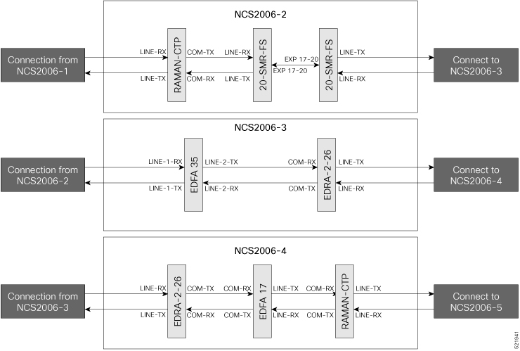
Connect an LC/LC fiber from the COM-TX port of the RAMAN-CTP card in NCS 2006-2 to the LINE-RX port of the 20-SMR-FS card in NCS 2006 -2.
-
Connect an LC/LC fiber from the COM-RX port of the RAMAN-CTP card in NCS 2006-2 to the LINE-TX port of the 20-SMR-FS card in NCS 2006 -2.
-
Connect an LC/LC fiber from the EXP 17–20 port of the 20-SMR-FS card in NCS 2006-2 to the EXP 17–20 port of the 20-SMR-FS card in NCS 2006-2.
-
Connect an LC/LC fiber from the LINE-TX port of the 20-SMR-FS card in NCS 2006-2 to the LINE-1-RX port of the EDFA–35 card in NCS 2006 -3.
-
Connect an LC/LC fiber from the LINE-RX port of the 20-SMR-FS card (NCS 2006-2) to the LINE-1-TX port of the EDFA–35 card (NCS 2006 -3).
-
Connect an LC/LC fiber from the LINE-2-TX port of the EDFA-35 card in NCS 2006 -3 to the COM-RX port of the EDRA-2-26 card in NCS 2006 -3.
-
Connect an LC/LC fiber from the LINE-2-RX port of the EDFA-35 card (NCS 2006 -3) to the COM-TX port of the EDRA-2-26 card in NCS 2006-3.
-
Connect an LC/LC fiber from the LINE-TX port of the EDRA-2-26 card in NCS 2006-3 to the LINE-RX port of the EDRA-2-26 card in NCS 2006 -4.
-
Connect an LC/LC fiber from the LINE-RX port of the EDRA-2-26 card in NCS 2006-3 to the LINE-TX port of the EDRA-2-26 card in NCS 2006 -4.
-
Connect an LC/LC fiber from the COM-TX port of the EDRA-2-26 card in NCS 2006-4 to the COM-RX port of the EDFA-17 card in NCS 2006 -4.
-
Connect an LC/LC fiber from the COM-RX port of the EDRA-2-26 card in NCS 2006-4 to the COM-TX port of the EDFA-17 card in NCS 2006 -4.
-
Connect an LC/LC fiber from the COM-RX port of the EDRA-2-26 card (NCS 2006-4) to the COM-TX port of the EDFA-17 card in NCS 2006 -4.
-
Connect an LC/LC fiber from the LINE-TX port of the EDFA-17 card in NCS 2006-4 to the COM-RX port of the RAMAN-CTP card in NCS 2006-4.
-
Connect an LC/LC fiber from the LINE-RX port of the EDFA-17 card in NCS 2006-4 to the COM-TX port of the RAMAN-CTP card in NCS 2006-4.
-
Connect an LC/LC fiber from the LINE-TX port of the RAMAN-CTP card in NCS 2006-4 to the LINE-RX port of the RAMAN-CTP card in NCS 2006-5.
-
Connect an LC/LC fiber from the LINE-RX port of the RAMAN-CTP card in NCS 2006-4 to the LINE-TX port of the RAMAN-CTP card in NCS 2006-5.
-
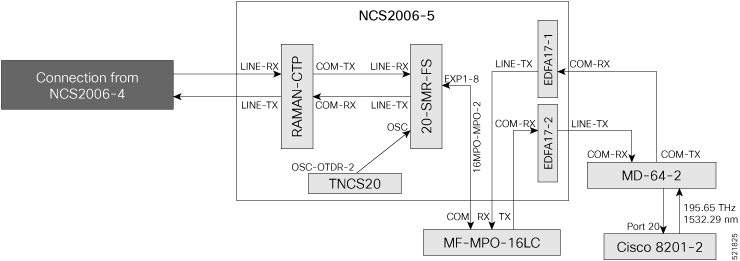
Connect an LC/LC fiber from the COM-TX port of the RAMAN-CTP card in NCS 2006-5 to the LINE-RX port of the 20-SMR-FS card in NCS 2006-5.
-
Connect an LC/LC fiber from the COM-RX port of the RAMAN-CTP card in NCS 2006-5 to the LINE-TX port of the SMR20 card in NCS 2006-5.
-
Connect an LC/LC fiber from the OSC-OTDR-2 port of the TNCS-2O card in NCS 2006 -5 to the OSC-TX port of the 20-SMR-FS card in NCS 2006 -5.
-
Connect a 16MPO-MPO-2 cable from the EXP1-8 port of the 20-SMR-FS card in NCS 2006-5 to the COM port of the MF-MPO-16LC module.
-
Connect an LC/LC fiber from the LINE-TX port of the EDFA-17-1 card in NCS 2006-5 to the RX port of the MF-MPO-16LC module.
-
Connect an LC/LC fiber from the COM-RX port of the EDFA-17-2 card in NCS 2006-5 to the TX port of the MF-MPO-16LC module.
-
Connect an LC/LC fiber from the COM-RX port of the EDFA17-1 card in NCS 2006-5 to the COM-TX port of the MD-64-2 module.
-
Connect an LC/LC fiber from the LINE-TX port of the EDFA-17-2 card in NCS 2006-5 to the COM-RX port of the MD-64-2 module.
Next steps
After you build the topology, perform these steps: