BGP Configuration Guide for Cisco 8000 Series Routers, Cisco IOS XR Releases

PDF

BGP optimal route reflectors

Want to summarize with AI?

Log in

Overview

Details BGP optimal route reflector functionality, including operational restrictions, the effect of ORR on route reflector client path selection, and step-by-step procedures to configure BGP ORR for route reflector clients.

A BGP optimal route reflector (ORR) is a virtual route reflector function that

  • calculates the best BGP path from the perspective of each route reflector (RR) client

  • runs multiple shortest path first (SPF) calculations per RR client or cluster to ensure path optimality, and

  • enables flexible placement of virtual route reflectors (vRR) in service provider networks without compromising path selection accuracy.

Traditional BGP route reflector limitations

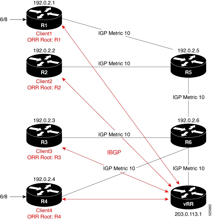
In traditional BGP deployments, a route reflector acts as a focal point within an autonomous system and advertises routes to RR clients based on the RR’s own path selection. When the RR is not optimally placed in the network topology, it can result in suboptimal routing decisions for RR clients, causing inefficient traffic flows.

Optimised client-specific routing with BGP ORR

BGP ORR addresses these limitations by running multiple SPF calculations from the perspective of each RR client or RR cluster. The system stores each client’s SPF results in a dedicated database, using these results to influence BGP best path selection. This process ensures every advertised route is optimal for the client’s specific network position, regardless of the vRR's location.

Benefits of BGP ORR

  • Calculates and advertises the best BGP path for each RR client’s viewpoint.

  • Enables vRR placement anywhere in the service provider network without sacrificing routing efficiency.

  • Allows network operators to scale RR memory and CPU resources according to operational requirements.

A service provider using network function virtualization (NFV) can deploy Cisco IOS XRv 9000 as a virtual route reflector in a central data center. BGP ORR optimizes routing for distributed RR clients, ensuring each receives the best available path despite the vRR’s remote placement.


Restrictions for BGP Optimal Route Reflection

Review these restrictions when configuring BGP Optimal Route Reflection:

  • BGP ORR considers only IGP-learned routes as rSPF (Reverse Shortest Path First) routes.

  • Routes learned via BGP-LU are out of scope for ORR calculations and are not supported.

  • BGP ORR does not support environments utilizing multiple IGP topologies.


Effect of BGP ORR on route reflector client path selection

The path a route reflector client selects in a BGP topology depends on whether BGP ORR is configured.

Example: BGP ORR topology

To illustrate the impact of BGP ORR on client path selection, consider the topology shown in Figure 1.

In this sample BGP topology, routers R1, R2, R3, R4, R5, and R6 are route reflector clients connected to a virtual route reflector (vRR). R1 and R4 advertise the prefix 6/8 to the vRR. Without BGP ORR, the vRR reflects the prefix based on its own path selection, which may not be optimal for all clients. With BGP ORR enabled, the vRR selects the best exit for each client based on the client’s location in the topology.

This table compares client path selection with and without BGP ORR:

Scenario Client (Example: R2) Exit point selected Selection basis
Without BGP ORR R2 R4 vRR selects best path from its own perspective
With BGP ORR configured R2 R1 vRR calculates best exit from the client's perspective (ORR Root: R2)

Key facts

  • Without BGP ORR:

    Route reflection uses the virtual route reflector’s (vRR) view of the network topology, which may not yield the optimal exit point for every client. In this case, the vRR considers R4 as the best path for all clients, including R2, even if R2 is topologically closer to R1.

  • With BGP ORR:

    The vRR evaluates topological distance from each client’s perspective (the ORR root), ensuring each client receives the route that represents its optimal exit point. For example, R2 receives the route from R1 if it is the closest.


Configure BGP ORR for a route reflector client

Enable optimal route reflection (ORR) on a virtual route reflector (vRR) for a specific client, apply the correct policies, ensure underlying MPLS TE support, and verify correct function.

Before you begin

  • Ensure you have administrative access to the vRR and root router.

  • Confirm that BGP and MPLS Traffic Engineering features are enabled and licensed on all relevant devices.

  • Gather these details:

    • BGP AS number

    • Client IP address

    • ORR root policy name

    • Required interface/loopback details

Procedure

1.

Enter BGP configuration mode and define the ORR statement using the client’s IP address and the appropriate ORR policy.

Example:

Router# configure
Router(config)# router bgp 6500
Router(config-bgp)# address-family ipv4 unicast
Router(config-bgp-af)# optimal-route-reflection g1 192.0.2.2
Router(config-bgp-af)# commit
2.

In BGP configuration mode, assign the ORR policy to the target neighbor (the RR client) for the relevant address family.

Example:

Router# configure
Router(config)# router bgp 6500
Router(config-bgp)# neighbor 10.0.0.1
Router(config-bgp-nbr)# address-family ipv4 unicast
Router(config-bgp-nbr-af)# optimal-route-reflection g1
Router(config-bgp-nbr-af)# commit
3.

On the root router, configure a minimal MPLS TE setup to advertise the router-ID that matches the configured root address on the vRR.

Example:

Router(config)# router isis 1
Router(config-isis)# is-type level-2-only 
Router(config-isis)# net 47.0000.0000.0005.00
Router(config-isis)# distribute link-state
Router(config-isis-af)# metric-style wide
Router(config-isis-af)# mpls traffic-eng level-2-only
Router(config-isis-af)# mpls traffic-eng router-id Loopback0
4.

Execute the show bgp command on the client (for example, R2) to verify whether the client received the best path.

Example:

R2# show bgp 10.0.0.0/8
Tue Apr  5 20:21:58.509 UTC
BGP routing table entry for 10.0.0.0/8
Versions:
  Process           bRIB/RIB  SendTblVer
  Speaker                  8           8
Last Modified: Apr  5 20:00:44.022 for 00:21:14
Paths: (1 available, best #1)
  Not advertised to any peer
  Path #1: Received by speaker 0
  Not advertised to any peer
  Local
    192.0.2.1 (metric 20) from 209.165.113.1 (192.0.2.1)
      Origin incomplete, metric 0, localpref 100, valid, internal, best, group-best
      Received Path ID 0, Local Path ID 1, version 8
      Originator: 192.0.2.1, Cluster list: 203.0.113.1

5.

Execute the show bgp command on the vRR to verify that the client is in the correct update-group and that the best path is reflected as intended.

Example:

VRR# show bgp 10.0.0.0/8
Thu Apr 28 13:36:42.744 UTC
BGP routing table entry for 10.0.0.0/8
Versions:
Process bRIB/RIB SendTblVer
Speaker 13 13
Last Modified: Apr 28 13:36:26.909 for 00:00:15
Paths: (2 available, best #2)
Advertised to update-groups (with more than one peer):
0.2
Path #1: Received by speaker 0
ORR bestpath for update-groups (with more than one peer):
0.1
Local, (Received from a RR-client)
192.0.2.1 (metric 30) from 192.0.2.1 (192.0.2.1)
Origin incomplete, metric 0, localpref 100, valid, internal, add-path
Received Path ID 0, Local Path ID 2, version 13
Path #2: Received by speaker 0
Advertised to update-groups (with more than one peer):
0.2
ORR addpath for update-groups (with more than one peer):
0.1
Local, (Received from a RR-client)
192.0.2.4 (metric 20) from 192.0.2.4 (192.0.2.4)
Origin incomplete, metric 0, localpref 100, valid, internal, best, group-best
Received Path ID 0, Local Path ID 1, version 13

6.

Execute the show bgp update-group 0.1 command, and verify whether the client (R2) is in update-group 0.1.

Example:

VRR# show bgp update-group 0.1 
Thu Apr 28 13:38:18.517 UTC

Update group for IPv4 Unicast, index 0.1:
Attributes:
Neighbor sessions are IPv4
Internal
Common admin
First neighbor AS: 65000
Send communities
Send GSHUT community if originated
Send extended communities
Route Reflector Client
ORR root (configured): g1; Index: 0
4-byte AS capable
Non-labeled address-family capable
Send AIGP
Send multicast attributes
Minimum advertisement interval: 0 secs
Update group desynchronized: 0
Sub-groups merged: 0
Number of refresh subgroups: 0
Messages formatted: 5, replicated: 5
All neighbors are assigned to sub-group(s)
Neighbors in sub-group: 0.2, Filter-Groups num:1
Neighbors in filter-group: 0.2(RT num: 0)
192.0.2.2

7.

Run the show orrspf database command to validate cost and root selection.

Example:

VRR# show orrspf database g1 
Thu Apr 28 13:39:20.333 UTC

ORR policy: g1, IPv4, RIB tableid: 0xe0000011
Configured root: primary: 192.0.2.2, secondary: NULL, tertiary: NULL
Actual Root: 192.0.2.2, Root node: 2000.0100.1002.0000

Prefix Cost
203.0.113.1 30
192.0.2.1 20
192.0.2.2 0
192.0.2.3 30
192.0.2.4 30
192.0.2.5 10
192.0.2.6 20

Number of mapping entries: 8