Cisco APIC Layer 3 Networking Configuration Guide, Release 6.2(x)

PDF

Cisco APIC Layer 3 Networking Configuration Guide, Release 6.2(x)

Create L3Out wizard

Want to summarize with AI?

Log in

Describes how the Create L3Out wizard simplifies connections between the ACI fabric and external Layer 3 networks by guiding you through the required settings, routing protocols, and interface profiles.


The Create L3Out wizard is a configuration tool introduced in APIC Release 4.2(1) that

  • guides you through the configuration of L3Out components, and

  • consolidates basic settings, routing protocols, and interface profiles into a single workflow.

Create L3Out wizard pages

The Create L3Out wizard organizes the configuration workflow into these pages:

  • The Identity page configures basic settings, static routing, and dynamic routing protocols.

  • The Nodes and Interfaces page configures node and interface profiles for Layer 2 and Layer 3 interface types.

  • The Protocols page configures policies for the protocols that you select on the Identity page .

  • The External EPG page configures the contract and subnets for the external EPG.


OSPF L3Out configuration example

An L3Out is a logical entity that enables an ACI fabric to exchange routing information with external networks. This example uses OSPF to connect the fabric to two external routers.

L3Out configuration context

The Create L3Out wizard provides options for configuring connectivity between the ACI fabric and external networks.

Note

This example uses Cisco APIC Release 4.2(x) and its associated GUI.


OSPF L3Out example topology

An OSPF L3Out topology is a network design that

  • uses Area 0 for OSPF routing.

  • connects two external routers to routed interfaces on two border leaf switches.

  • advertises bridge domain subnets to external networks.

  • uses contracts to permit communication between endpoint groups (EPGs) and external networks.

OSPF L3Out topology and configuration flow

The following figures show the example topology and its OSPF configuration.

Figure 1. OSPF L3Out topology with two external routers
Figure 2. OSPF configuration

Configure the example in this sequence:

  1. Create the L3Out with OSPF parameters, node and interface profiles, OSPF interface profiles, and an external EPG that uses the External Subnets for the External EPG scope.

  2. Advertise the bridge domain subnet by using the default-export route map and enabling the Advertise Externally scope on the subnet.

  3. Create a contract between EPG1 and L3Out EPG1 to permit communication between the EPG and the external network.


L3Out example prerequisites

An L3Out configuration prerequisite is a tenant object that must exist before you configure an L3Out.

This example requires

  • VRF1

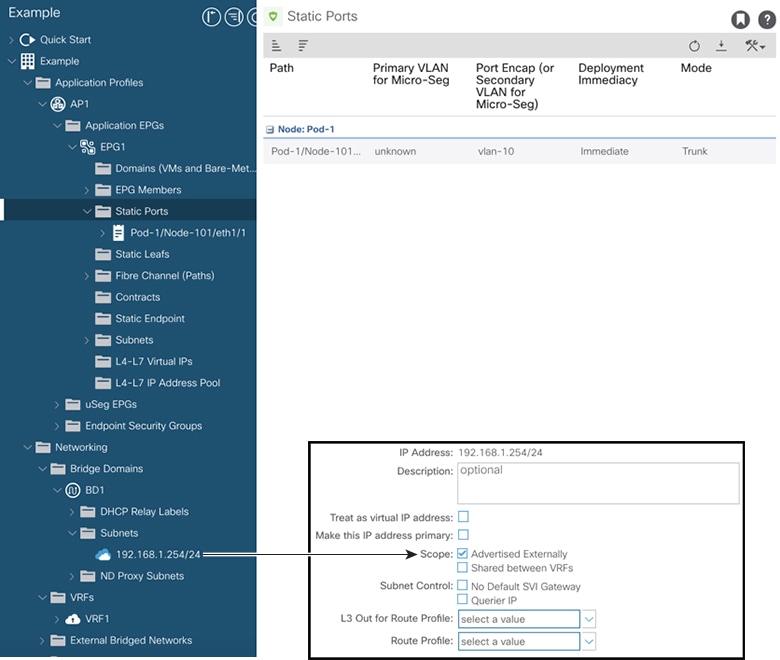
  • BD1 with subnet 192.168.1.254/24

  • EPG1 with a static port that connects to the endpoints

Configuration scope

This example covers only the L3Out configuration. It does not cover the configuration of virtual routing and forwarding instances (VRFs), bridge domains (BDs), endpoint groups (EPGs), application profiles, or access policies.

The following figure shows the tenant objects required for the example L3Out.

Figure 3. Tenant objects required for the L3Out example

Create an example OSPF L3Out using the Create L3Out wizard

This task creates the OSPF L3Out shown in OSPF L3Out example topology. After you complete this task, Cisco ACI contains two border leaf switches that establish OSPF neighbor relationships with two external routers.

Procedure

  1. In the Navigation pane, under Tenant Example, choose Networking > L3Outs.

  2. Right-click L3Outs, and choose Create L3Out.

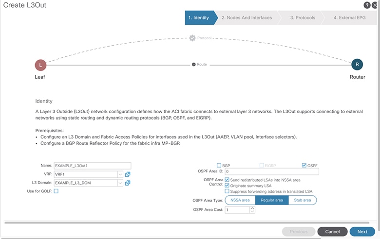
  3. On the Identity page of the Create L3Out wizard, configure the L3Out identity.

    The following figure shows the identity settings used in this example.

    Figure 4. L3Out identity settings
    1. In the Name field, enter EXAMPLE_L3Out1.
    2. From the VRF drop-down list, choose VRF1.
    3. From the L3 Domain drop-down list, choose EXAMPLE_L3DOM.
    4. Check the OSPF check box.
    5. From the OSPF Area ID drop-down list, choose 0 or backbone.
    6. From the OSPF Area Type drop-down list, choose Regular area.
    7. Retain the default values for the remaining fields.
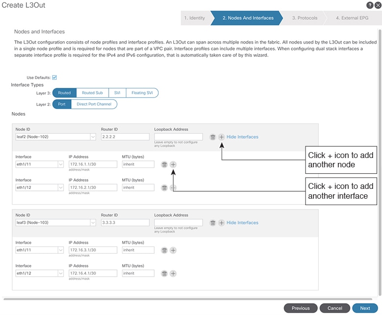
  4. Click Next to open the Nodes and Interfaces page, and configure leaf2.

    The following figure shows the node and interface settings used in this example.

    Figure 5. Node and interface settings
    1. In the Interface Types area, choose Routed for Layer 3 and Port for Layer 2.
    2. In the Nodes area, choose leaf2 (Node 102) from the Node ID drop-down list.
    3. In the Router ID field, enter 2.2.2.2.
    4. Clear the automatically populated value from the Loopback Address field.

      This example does not use a loopback address.

    5. From the Interface drop-down list, choose eth1/11.
    6. In the IP Address field, enter 172.16.1.1/30.
    7. Retain inherit in the MTU field.
    8. Click the + icon next to the MTU field to add another interface to leaf2.
    9. From the new Interface drop-down list, choose eth1/12.
    10. In the IP Address field, enter 172.16.2.1/30.
    11. Retain inherit in the MTU field.
  5. Click the + icon next to the Loopback Address field to add leaf3, and configure its interfaces.

    Note

    The wizard displays a new Nodes area below the area for leaf2.

    1. In the new Nodes area, choose leaf3 (Node 103) from the Node ID drop-down list.
    2. In the Router ID field, enter 3.3.3.3.
    3. Clear the automatically populated value from the Loopback Address field.

      This example does not use a loopback address.

    4. From the Interface drop-down list, choose eth1/11.
    5. In the IP Address field, enter 172.16.3.1/30.
    6. Retain inherit in the MTU field.
    7. Click the + icon next to the MTU field to add another interface to leaf3.
    8. From the new Interface drop-down list, choose eth1/12.
    9. In the IP Address field, enter 172.16.4.1/30.
    10. Retain inherit in the MTU field.

      The wizard contains the node, interface, and IP address information for each routed interface.

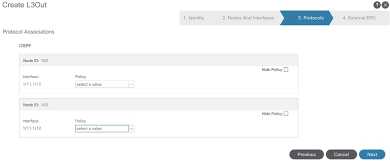
  6. Click Next to open the Protocols page.

    The following figure shows the protocol settings used in this example.

    Figure 6. OSPF protocol settings

    Use the Protocols page to configure OSPF interface policy settings, such as the hello interval and network type.

    This example uses the default OSPF interface profile. The default profile sets the network type to Unspecified, which uses the broadcast network type. To use the point-to-point network type for a subinterface, refer to Change the OSPF Interface-Level Parameters (Optional).

  7. Click Next to open the External EPG page.

    The wizard displays the L3Out EPG settings that classify traffic so that contracts can apply to it.

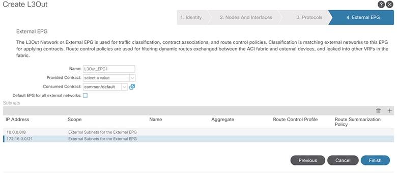
  8. On the External EPG page, configure the external EPG.

    The following figure shows the external EPG settings used in this example.

    Figure 7. External EPG settings
    1. In the Name field, enter L3Out_EPG1.
    2. Leave the Provided Contract field blank.

      In this example, EPG1 provides the contract, so L3Out_EPG1 does not require a provided contract.

    3. From the Consumed Contract drop-down list, choose default.
  9. Clear the Default EPG for all external networks check box, and add the external network subnet.

    1. In the Subnets area, click the + icon to open the Create Subnet dialog box.
    2. In the IP Address field, enter 10.0.0.0/8.
    3. Under External EPG Classification, check the External Subnets for the External EPG check box, and click OK.
  10. In the Subnets area, click the + icon again to add the L3Out interface subnet.

    Note

    As a best practice, add the L3Out interface subnets so that endpoints can communicate with the interface IP addresses.

    1. In the IP Address field, enter 172.16.0.0/21.

      This subnet includes all the interfaces in the L3Out. Alternatively, add each routed interface subnet separately.

    2. Under External EPG Classification, check the External Subnets for the External EPG check box, and click OK.
    3. Click Finish.

The wizard deploys the OSPF L3Out.


This example uses the default-export route map with an IP prefix list to advertise the BD subnet.

Note

The default-export route map applies to all route advertisements from EXAMPLE_L3Out1 rather than to a specific object association.

Procedure

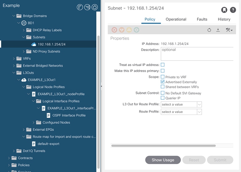
  1. In the Navigation pane, choose Tenant <tenant-name> > Networks > Bridge Domains > BD1 > Subnets > 192.168.1.254/24.

    The following figure shows the scope configuration for the BD subnet.

    Figure 8. BD subnet scope
  2. For the subnet scope, check the Advertised Externally check box.

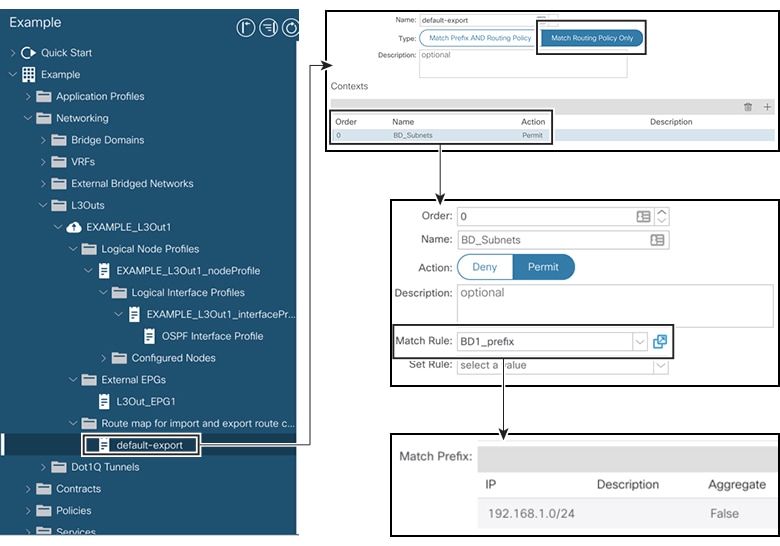
  3. Under EXAMPLE_L3Out1, select Route map for import and export route control.

    The following figure shows the route-map location under the L3Out.

    Figure 9. L3Out route-map configuration
  4. Right-click Route map for import and export route control, and choose Create Route map for import and export route control.

  5. In the Create Route map for import and export route control dialog box, enter default-export in the Name field.

  6. From the Type drop-down list, choose Match Routing Policy Only.

    Note

    When you choose Match Routing Policy Only, this route map controls all route advertisements from the L3Out. BD associations and export route-control subnets configured under the external EPG do not apply. Configure match rules for every route that the L3Out must advertise.

    If you choose Match Prefix and Routing Policy, the fabric evaluates the route-map match rules in addition to BD-to-L3Out associations and export route-control subnets under the external EPG.

    Use Match Routing Policy Only for a simpler configuration that is easier to maintain.

  7. In the Contexts area, click the + icon to open the Create Route Control Context dialog box, and configure the route-control context.

    1. In the Order field, enter 0.

      This example uses one route-control context.

    2. In the Name field, enter BD_Subnets.
    3. From the Action drop-down list, choose Permit.

      The Permit action allows the route map to advertise prefixes that match the configured rule.

  8. In the Match Rule field, create an IP prefix-list match rule for the BD subnet.

    1. Choose Create Match Rule for a Route-Map.
    2. In the Name field, enter BD1_prefix.
    3. In the Match Prefix area, click the + icon, and enter 192.168.1.0/24.

The default-export route map uses the BD1_prefix match rule to permit advertisement of the 192.168.1.0/24 BD subnet through EXAMPLE_L3Out1.


Verify the L3Out contract configuration

Use this procedure to verify the contract that permits communication between endpoint 192.168.1.1 and external prefix 10.0.0.0/8. The configuration can also include the optional 172.16.0.0/21 prefix.

In this example, EPG1 represents the endpoint, and L3Out_EPG1 represents the external prefixes.

Before you begin

Complete the Create L3Out wizard and configure the required contract before you begin.

Procedure

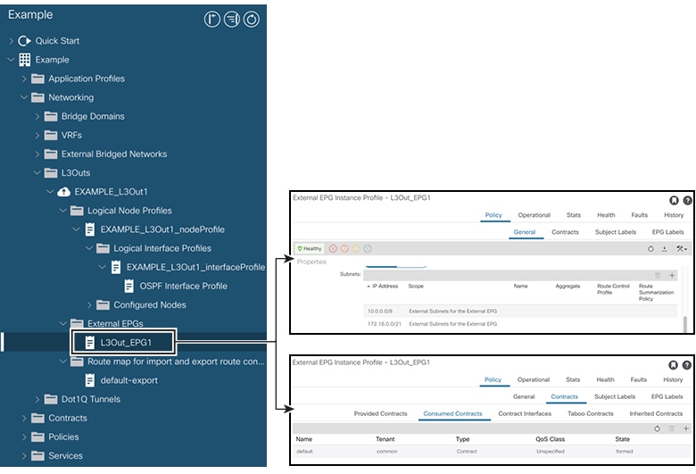
  1. Under the L3Out, choose External EPGs > L3Out_EPG1.

    The following figure shows the external EPG configuration.

    Figure 10. External EPG configuration
  2. In the Work pane, under External EPG Instance Profile, choose Policy > General.

  3. In the Properties area, verify that 10.0.0.0/8 and, if configured, 172.16.0.0/21 use the External Subnets for the External EPG scope.

  4. Click the Contracts subtab, and verify that L3Out_EPG1 consumes the expected contract.

  5. In the Navigation pane, choose Application Profiles > <application-profile-name> > Application EPGs > EPG1 > Contracts.

  6. Verify that EPG1 provides the contract that L3Out_EPG1 consumes.

The contract permits communication between EPG1 and the external prefixes represented by L3Out_EPG1.


Change OSPF interface-level parameters

Before you begin

Configure the node-level OSPF parameters before you begin.

Use this procedure to apply a hello interval, network type, and other OSPF settings to a specific L3Out interface.

Procedure

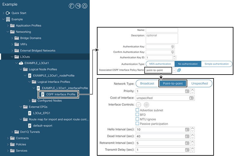
  1. In the Navigation pane, under the L3Out, choose Logical Interface Profile > EXAMPLE_L3Out1_interfaceProfile > OSPF Interface Profile.

    The following figure shows the OSPF interface-profile configuration.

    Figure 11. OSPF interface-profile configuration
  2. In the Work pane, under Properties, choose the OSPF interface policy that contains the required interface-level parameters.

The selected OSPF interface policy determines the interface-level OSPF parameters for the L3Out interfaces.