Explains Layer 3 multicast support on SVI L3Out configurations that enables PIM adjacencies between ACI border leaf switches and external multicast devices.
Layer 3 multicast on an SVI L3Out is a network feature that
-
adds support for enabling PIM on L3Out SVIs
-
allows ACI border leaf switches configured with an L3Out SVI to establish PIM adjacencies with external multicast routers or firewalls, and
-
supports LAN-like topologies where firewalls are deployed in active/standby pairs connecting to the fabric on the same VLAN and subnet.
L3Out SVI configuration details
An L3Out SVI is an interface type where a Layer 3 SVI interface is configured on every border leaf switch where the SVI is deployed. When PIM is enabled on an L3Out that is configured with an SVI, the PIM protocol will be enabled on the border leaf switch that is part of the SVI. All SVIs will then form PIM adjacencies with each other and any external PIM-enabled devices.
Beginning with release 5.2(3), support is available for Layer 3 multicast on an SVI L3Out.
L3Out to firewall topology
This example shows an L3Out to firewalls topology.
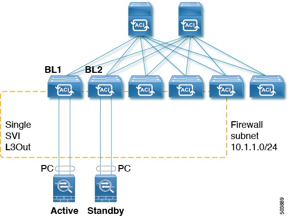
In this example, BL1 and BL2 are the border leaf switches on the fabric. Both border leaf switches are on the same SVI L3Out that connects to the external firewalls. Each firewall is connected to one of the two border leaf switches over a port-channel (non-VPC).
This topology exhibits these characteristics:
-
Each border leaf switch will form a PIM neighbor adjacency to the active firewall.
-
BL2 in the example will peer to the active firewall over the fabric tunnel for the L3Out external bridge domain.
-
The active firewall can send PIM joins/prunes to both BL1 and BL2.
-
One of the two border leaf switches will send the PIM joins towards the firewall. The border leaf switch that sends the PIM join towards the firewall is determined by the stripe winner selection for the multicast group (group and source for SSM).
-
BL2 can be selected as the stripe winner for a multicast group. BL2 in the example topology is not directly connected to the active firewall. BL1 will notify BL2 that it is the directly connected reverse path forwarding (RPF) to the source. BL2 can send the PIM via BL1. BL2 must be able to perform a recursive lookup for the IP address of the firewall. This functionality is provided by the attached-host redistribution feature. A route-map matching the firewall subnet must be configured for attached-host redistribution on the L3Out.
Another example shows an L3Out SVI to external switches or routers.
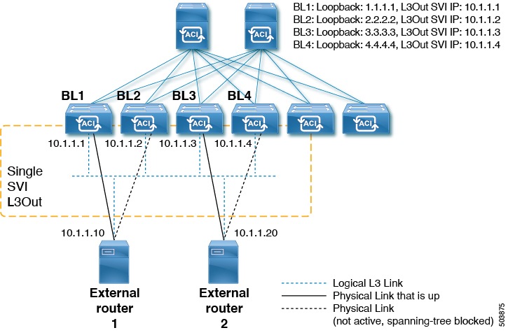
With respect to the Layer 3 multicast states and multicast data traffic, these components are affected in this manner:
-
BL1, BL2, BL3, and BL4 are the border leaf switches on the fabric. All of these border leaf switches are on the same SVI L3Out that connect to the external boxes, where the external boxes could be any external switch or router.
-
Logically, the Layer 3 link is up between the border leaf switches and the external routers. So a full mesh adjacency exists with regards to unicast routing protocol(s) or PIM across the border leaf switches and the external switches/routers on the SVI L3Out.
-
Since the SVI L3Out is a bridge domain, even if there are multiple physical connections from border leaf switches to the external switches/routers, only one link among them will be up at the Layer 2 level to each external switch/router. All of the other links will be blocked by STP.
For example, in the figure above, only these links at the Layer 2 level are up:
-
The link between BL1 and external router 1
-
The link between BL3 and external router 2
So for all of the other border leaf switches, this makes the IP addresses 10.1.1.10 reachable only through BL1 and 10.1.1.20 reachable only through BL3.
-
Guidelines and limitations
An attached-host route-map must be configured for the PIM-enabled SVI L3Out. This route-map should match all directly-connected external PIM neighbors. The 0.0.0.0/0 subnet can be used.
For the Layer 3 multicast on an SVI L3Out feature, these areas are supported or unsupported:
Supported:
-
Protocol Independent Multicast (PIM) Any Source Multicast (ASM) and Source-Specific Multicast (SSM)
-
SVI with physical interfaces
-
SVI with direct port-channels (non-VPC)
-
All topology combinations:
-
Source inside receiver inside (SIRI)
-
Source inside receiver outside (SIRO)
-
Source outside receiver inside (SORI)
-
Source outside receiver outside (SORO)
-
Unsupported:
-
Layer 3 multicast with VPC over an SVI L3Out
-
Source or receiver hosts connected directly on the SVI subnet (source or receiver hosts must be connected behind a router on the SVI L3Out)
-
Stretched SVI L3Out between local leaf switches (ACI main data center switches) and remote leaf switches
-
Stretched SVI L3Out across sites (Cisco ACI Multi-Site)
-
SVI L3Out for PIMv6
-
Secondary IP addresses. PIM joins/prunes will not be processed if sent to the secondary IP address of the border leaf switch. Secondary IP address are typically used for configuring a shared (virtual) IP address across border leaf switches for static routing. We recommend that you use dynamic routing when configuring PIM over SVIs or create static routes to each border leaf switch primary address.
-
Floating L3Out SVIs