Cisco APIC Layer 3 Networking Configuration Guide, Release 6.2(x)

PDF

Cisco APIC Layer 3 Networking Configuration Guide, Release 6.2(x)

Cisco ACI GOLF

Want to summarize with AI?

Log in

Explains how GOLF provides WAN connectivity for ACI fabrics by carrying BGP EVPN over OSPF and aggregating tenant BGP sessions toward a DCIG.


The Cisco ACI GOLF is a WAN connectivity feature that

  • carries BGP EVPN over OSPF between WAN routers and spine switches,

  • aggregates tenant BGP sessions toward a DCIG, and

  • extends the network over Layer 3 subinterfaces on spine fabric ports.

Infrastructure tenant connectivity

A Layer 3 external outside network (l3extOut) in the infra tenant provides physical connectivity between a spine switch and GOLF. It includes

  • a logical node profile (LNodeP),

  • a provider label for the GOLF l3extOut,

  • OSPF policies, and

  • BGP policies.

Application tenant connectivity

Application tenants use the physical connectivity that is defined in the infra tenant. Each tenant l3extOut requires

  • an external EPG (l3extInstP) with subnets and contracts. The subnet scope controls import route control, export route control, and security policies. Configure the BD subnet as Advertised Externally and place it in the same VRF as the application EPG and the GOLF L3Out EPG,

  • explicit contracts between the application EPG and the GOLF L3Out EPG. Contract Preferred Groups do not govern this communication,

  • an l3extConsLbl consumer label that matches the provider label on the GOLF l3extOut in the infra tenant. The matching labels enable application EPGs in other tenants to consume the external L3Out EPG associated with LNodeP, and

  • a BGP EVPN session in the matching provider l3extOut in the infra tenant. The session advertises the tenant routes that are defined in the tenant l3extOut.

The following figure shows the GOLF topology.
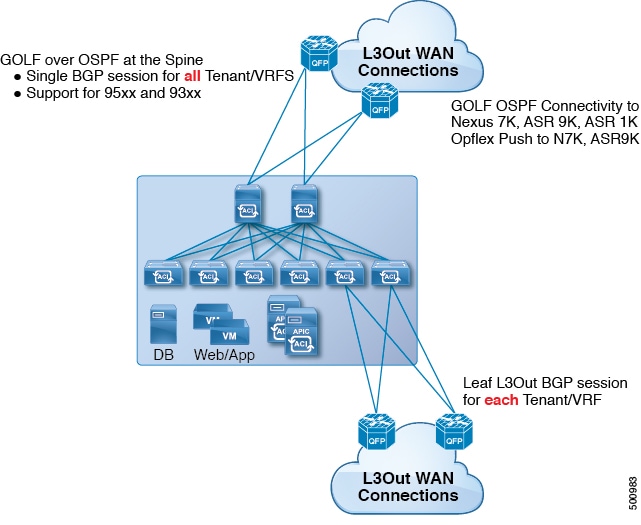
Figure 1. GOLF topology


Guidelines and limitations for GOLF

These guidelines identify the deployment requirements and limitations for GOLF that affect platform support, control-plane stability, and routing behavior.

Feature and platform support

  • GOLF does not support shared services.

  • GOLF does not support transit routing.

  • A GOLF router must advertise at least one route to Cisco Application Centric Infrastructure (ACI) before it can receive traffic. The fabric does not create a tunnel between the leaf switches and external routers until Cisco ACI receives a route from an external router.

  • All Cisco Nexus 9000 Series switches operating in Cisco ACI mode support GOLF. All line cards and fabric modules for Cisco Nexus 9500 platform switches operating in Cisco ACI mode also support GOLF. With Cisco APIC release 3.1(x) and later, supported hardware includes the N9K-C9364C switch.

  • The fabric supports only one GOLF provider policy on spine switch interfaces.

  • In Cisco APIC releases earlier than 2.0(2), GOLF is not supported with Cisco ACI Multi-Pod. In release 2.0(2), both features can operate in the same fabric only on Cisco Nexus 9000 switches whose model names do not end in EX, such as the N9K-9312TX. In release 2.1(1) and later, both features can operate together on all switches used in Cisco ACI Multi-Pod and EVPN topologies.

Configuration and convergence requirements

  • After you configure GOLF on a spine switch, wait for the control plane to converge before you configure it on another spine switch.

  • A spine switch can belong to multiple provider GOLF outside networks. Assign a unique provider label, OSPF area, and loopback address to each l3extOut object.

  • The BGP EVPN session in the matching provider l3extOut object in the infra tenant advertises the tenant routes that are defined in that object.

  • If a deployment has three GOLF L3Outs, only one L3Out has a provider or consumer label, and 0/0 export aggregation is configured, Cloud APIC exports all routes. This behavior is the same as an existing tenant l3extOut object on a leaf switch.

  • The default bgpPeerPfxPol policy limits the number of routes to 20,000. Increase the limit as needed for Cisco ACI WAN Interconnect peers.

Routing caveats

  • If an ERSPAN session has a SPAN destination in a GOLF-enabled VRF and its source interfaces are on a spine switch, the fabric sends the transit prefix from a non-GOLF L3Out to the GOLF router with an incorrect BGP next hop.

  • When a spine switch peers directly with a DCI router, transit routes from leaf switches to the ASR use the leaf switch PTEP as the next hop. The ASR requires a static route for the TEP range of that Cisco ACI pod. If the DCI is dual-homed to the same pod, assign the static route the same administrative distance as the route received through the other link.

  • If one spine switch has two provider l3extOut objects, one with provider label prov1 peering with DCI 1 and the other with provider label prov2 peering with DCI 2, a tenant VRF consumer label that refers to either provider label causes the fabric to advertise the tenant route through both DCI 1 and DCI 2.

  • When you aggregate GOLF OpFlex VRFs, do not leak routes in the Cisco ACI fabric or on the GOLF device between a GOLF OpFlex VRF and another VRF. An external device other than the GOLF router must perform the VRF leaking.

Note

Cisco ACI does not support IP fragmentation. Therefore, when you configure Layer 3 Outside (L3Out) connections to external routers, or Multi-Pod connections through an Inter-Pod Network (IPN), it is recommended that the interface MTU is set appropriately on both ends of a link. On some platforms, such as Cisco ACI, Cisco NX-OS, and Cisco IOS, the configurable MTU value does not take into account the Ethernet headers (matching IP MTU, and excluding the 14-18 Ethernet header size), while other platforms, such as IOS-XR, include the Ethernet header in the configured MTU value. A configured value of 9000 results in a max IP packet size of 9000 bytes in Cisco ACI, Cisco NX-OS, and Cisco IOS, but results in a max IP packet size of 8986 bytes for an IOS-XR untagged interface.

For the appropriate MTU values for each platform, see the relevant configuration guides.

We highly recommend that you test the MTU using CLI-based commands. For example, on the Cisco NX-OS CLI, use a command such as ping 1.1.1.1 df-bit packet-size 9000 source-interface ethernet 1/1.


Shared APIC GOLF connections

An APIC GOLF connection is a routed connection that

  • enables multiple Multi-Site sites to use the same DCI infrastructure,

  • requires coordinated manual or automatic route targets for GOLF VRFs and route-target synchronization between ACI spine switches and DCIs through OpFlex, and

  • uses DCI route maps to prevent unintended route propagation between VRFs that must remain isolated.

Route-target configuration and traffic isolation

The following table shows how identical fabric IDs and overlapping VNIDs can assign the same route target to different VRFs at different sites.

Table 1. VRF route-target conflict example

Attribute

Site 1

Site 2

ASN

100

100

Fabric ID

1

1

VRF A VNID

1000

2000

VRF A import and export route target

100: [1] 1000

100: [1] 2000

VRF B VNID

2000

1000

VRF B import and export route target

100: [1] 2000

100: [1] 1000

In this example, VRF A at Site 1 shares a route target with VRF B at Site 2, and VRF B at Site 1 shares a route target with VRF A at Site 2. Without route filtering, each pair can exchange traffic across VRF boundaries.

DCI route maps help maintain control-plane stability and prevent transit-route leakage in these BGP session arrangements:

  • Site 1 uses iBGP with the DCI, and Site 2 uses eBGP with the DCI.

  • Site 1 uses eBGP with the DCI, and Site 2 uses iBGP with the DCI.

  • Site 1 and Site 2 use eBGP with the DCI.

  • Site 1 is an iBGP RR client of the DCI, the DCI acts as the RR, and Site 2 uses iBGP with the DCI.

Route map implementation

In this example, route maps use different BGP communities in the inbound and outbound peer policies. When the DCI receives routes from the GOLF spine at one site, the outbound peer policy toward the GOLF spine at another site filters the routes by the community defined in the inbound peer policy. A separate outbound policy removes the community before advertising the routes toward the WAN.


Configure the ACI GOLF service by using the GUI

The infra tenant provides GOLF services that other tenants can consume. Configure the provider L3Out in the infra tenant and a consumer L3Out in each tenant that uses the service.

Procedure

  1. Choose Tenants > infra.

  2. In Networking, right-click L3Outs, and select Create L3Out.

    1. For Name, VRF, and L3 Domain, enter the values for your deployment.
    2. From Use For, select Golf.

      Provider Label and Route Target appear.

    3. For Provider Label, enter a label, such as golf.
    4. From Route Target, select Automatic or Explicit.
      • Automatic: Enables automatic BGP route-target filtering on the VRFs associated with this L3Out.

      • Explicit: Uses explicitly configured BGP route-target policies on the VRFs associated with this L3Out.

      Note

      Configure explicit route-target policies in BGP Route Target Profiles on the BGP page of Create VRF. If you select Automatic, explicit route-target policies configured for the VRF can disrupt BGP routing.

    5. Keep BGP selected, retain the remaining default settings, and click Next.

      The Nodes and Interfaces page opens.

  3. On Nodes and Interfaces, configure the spine node and interface settings.

    1. From Node ID, select a spine switch node ID.
    2. For Router ID, enter the router ID.
    3. Optional: If needed, replace the value in Loopback Address with a different IP address.

      By default, Loopback Address contains the value from Router ID. Clear the value if you do not want to use the router ID as the loopback address.

    4. Keep External Control Peering selected.
    5. Enter the remaining node and interface values for the selected Layer 3 and Layer 2 options.

      The available settings depend on the selected Layer 3 and Layer 2 options.

    6. Click Next.

      The Protocols page opens.

  4. On Protocols, configure the routing protocol settings.

    1. For Peer Address in BGP Loopback Policies or BGP Interface Policies, enter the peer IP address.
    2. For EBGP Multihop TTL, enter the connection TTL.

      The valid range is 1-255 hops. Enter 0 to leave the TTL unspecified. The default value is 0.

    3. For Remote ASN, enter the neighbor autonomous system number in four-byte asplain format.

      The valid range is 1-4294967295.

      Note

      ACI does not support autonomous system numbers in asdot or asdot+ format.

    4. From OSPF, select the default OSPF policy, an existing OSPF policy, or Create OSPF Interface Policy.
    5. Click Next.

      The External EPG page opens.

  5. On External EPG, configure the external network and contract settings.

    1. For Name, enter the external network name.
    2. For Provided Contract, enter the provided contract name.
    3. For Consumed Contract, enter the consumed contract name.
    4. Optional: To advertise only specific transit routes, clear Allow All Subnet, and specify the subnets and controls in Subnets.

      Subnets appears when you clear Allow All Subnet.

    5. Click Finish.
  6. For each tenant that consumes the service, choose tenant_name > Networking > L3Outs.

    1. Right-click L3Outs, and select Create L3Out.
    2. For Name, VRF, and L3 Domain, enter the values for your deployment.
    3. Select Use for GOLF.
    4. From Label, select Consumer.
    5. For Consumer Label, enter the provider label that you configured earlier, such as golf.
    6. Click Next, and then click Finish.

The infra tenant provides the GOLF service, and the configured tenants can consume the service through their L3Outs.