ACI Fabric Optimizes Modern Data Center Traffic Flows
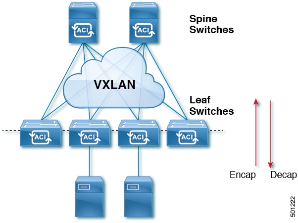
The ACI architecture is a spine-leaf network design that optimizes modern data center traffic by decoupling Layer 2 domains from the underlying Layer 3 infrastructure using VXLAN.
-
Supports increased east-west traffic demands driven by modern application designs.
-
Provides a single switch abstraction for bridging and routing capabilities.
-
Enables Layer 2 adjacency for virtual machine mobility and clustering software across the fabric.
Traffic Flow and Fabric Architecture
Traditional data center designs rely on north-south traffic patterns and Spanning Tree Protocol, which often results in blocked links and suboptimal paths. The ACI fabric improves upon these designs through the following mechanisms:
-
Encapsulation and policy application at the fabric entry point.
-
Forwarding across the fabric through a spine switch with a maximum of two hops.
-
Utilization of IS-IS and COOP for endpoint-to-endpoint communication.
-
Implementation of MP-BGP for propagating routing information between software-defined networks and external routers.
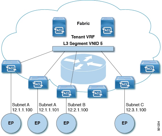
The following figure illustrates the ACI fabric architecture.

 Feedback