L2VPN Configuration Guide for Cisco 8000 Series Routers, Cisco IOS XR Releases

PDF

L2VPN Configuration Guide for Cisco 8000 Series Routers, Cisco IOS XR Releases

How MPLS PW traffic load balancing works on P routers

Want to summarize with AI?

Log in

Explains MPLS pseudowire traffic load balancing on P routers by describing control word and flow label mechanisms, load-balancing topologies, and provides configuration procedures for effective traffic distribution and increased network efficiency.


An L2VPN PE sends frames over an MPLS pseudowire (PW) by encapsulating each Ethernet frame into an MPLS frame. The frame includes at least one PW label and often an IGP label to reach the remote PE. The MPLS network uses one of several available paths to transport the frame to the remote PE.

Summary

The key components involved in the process are:

  • L2VPN provider edge (PE) routers: Encapsulate Ethernet frames into MPLS frames and initiate the pseudowire traffic across the network.

  • Provider routers (P routers): Select next-hop routers and balance traffic over eligible links using path selection and hashing algorithms.

  • IGP topology and MPLS TE tunnel paths: Determine the available equal-cost paths through the network for traffic distribution.

MPLS pseudowire (PW) traffic load balancing ensures that provider routers distribute traffic efficiently across multiple paths while maintaining packet order for each traffic flow.

Workflow
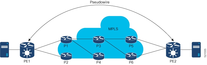
These stages describe how MPLS PW traffic load balancing works on P routers.

  1. Path selection by PE: PE1 selects P1 or P2 as the first MPLS P router toward PE2.
  2. Next-hop selection by P routers: If PE1 selects P1, P1 then chooses P3 or P4 for the next hop.
  3. Determining available paths: The IGP topology and MPLS TE tunnel path determine which paths are eligible for traffic.
  4. Balancing traffic loads: Providers balance traffic across multiple links to prevent.
  5. Hash-based path assignment: The core hashing algorithm assigns pseudowire traffic to specific paths.
  6. Handling high-bandwidth flows: Multiple high-bandwidth pseudowires can map to the same physical link, which may cause congestion.
  7. Preserving packet order: Packets from one traffic flow must follow the same path to prevent out-of-order frames.
  8. Enhancing load balancing: Control word and flow label methods are applied to improve the accuracy of MPLS PW load balancing.

Result

MPLS PW traffic is efficiently distributed across all eligible paths in the provider network, ensuring packets from a given flow remain in order and network resources are optimally utilized.

Load balance MPLS PW traffic using control word and flow label

Control word and flow label load balancing is a pseudowire forwarding method that

  • prevents misidentification of Ethernet pseudowire packets as IP packets

  • identifies individual packet flows within a pseudowire, and

  • improves traffic distribution across ECMP paths or link-bundled paths in the core.

Feature history

The feature history table lists release support for this feature.

Table 1. Feature History Table

Feature Name

Release Information

Feature Description

Load Balance MPLS PW Traffic using Flow-Label

Release 26.2.1

Introduced in this release on: Modular Systems (8800 [LC ASIC: K100])(select variants only*);

*This feature is supported on Cisco 88-LC1-48Y8H-EM line cards.

Load Balance MPLS PW Traffic using Control-Word

Release 26.2.1

Introduced in this release on: Modular Systems (8800 [LC ASIC: K100])(select variants only*);

*This feature is supported on Cisco 88-LC1-48Y8H-EM line cards.

Load Balance MPLS PW Traffic using Control-Word

Release 25.4.1

Introduced in this release on: Fixed Systems (8010 [ASIC: A100])(select variants only*)

This feature is supported on:

  • 8011-32Y8L2H2FH

  • 8011-12G12X4Y-A/D

Load Balance MPLS PW Traffic using Flow-Label

Release 25.4.1

Introduced in this release on: Fixed Systems (8010 [ASIC: A100])(select variants only*)

This feature is supported on:

  • 8011-32Y8L2H2FH

  • 8011-12G12X4Y-A/D

Load Balance MPLS PW Traffic using Control-Word

Release 25.1.1

Introduced in this release on: Fixed Systems (8010 [ASIC: A100])(select variants only*)

*This feature is supported on Cisco 8011-4G24Y4H-I routers.

Load Balance MPLS PW Traffic using Flow-Label

Release 25.1.1

Introduced in this release on: Fixed Systems (8010 [ASIC: A100])(select variants only*)

*This feature is supported on Cisco 8011-4G24Y4H-I routers.

Load Balance MPLS PW Traffic using Flow-Label

Release 24.4.1

Introduced in this release on: Fixed Systems (8700) (select variants only*)

*The load balancing with flow-label functionality is now extended to the Cisco 8712-MOD-M routers.

Load Balance MPLS PW Traffic using Control-Word

Release 24.4.1

Introduced in this release on: Fixed Systems (8700) (select variants only*)

*The load balancing with control-word functionality is now extended to the Cisco 8712-MOD-M routers.

Load Balance MPLS PW Traffic using Flow-Label

Release 24.3.1

Introduced in this release on: Fixed Systems (8200 [ASIC: Q200, P100], 8700 [ASIC: P100])(select variants only*); Modular Systems (8800 [LC ASIC: Q100, Q200, P100])(select variants only*)

*The load balancing with flow-label functionality is now extended to:

  • 8212-48FH-M

  • 8711-32FH-M

  • 88-LC1-52Y8H-EM

  • 88-LC1-12TH24FH-E

Load Balance MPLS PW Traffic using Control-Word

Release 24.3.1

Introduced in this release on: Fixed Systems (8200 [ASIC: Q200, P100], 8700 [ASIC: P100])(select variants only*); Modular Systems (8800 [LC ASIC: Q100, Q200, P100])(select variants only*)

*The load balancing with control-word functionality is now extended to:

  • 8212-48FH-M

  • 8711-32FH-M

  • 88-LC1-52Y8H-EM

  • 88-LC1-12TH24FH-E

Load Balance MPLS PW Traffic using Flow-Label

Release 24.2.11

Introduced in this release on: Modular Systems (8800 [LC ASIC: P100]) (select variants only*)

*The load balancing with flow-label functionality is now extended to routers with the 88-LC1-36EH line cards.

Load Balance MPLS PW Traffic using Control-Word

Release 24.2.11

Introduced in this release on: Modular Systems (8800 [LC ASIC: P100]) (select variants only*)

*The load balancing with control-word functionality is now extended to routers with the 88-LC1-36EH line cards.

Load Balance MPLS PW Traffic using Flow-Label

Release 7.3.15

The flow-label provides the capability to identify individual flows within a pseudowire and provides routers the ability to use these flows to load balance traffic. Individual flows are determined by the hashing algorithm configured under L2VPN. Similar packets with the same source and destination addresses are all said to be in the same flow. A flow-label is created based on indivisible packet flows entering a pseudowire and is inserted as the lowermost label in the packet. Routers can use the flow-label for load balancing which provides a better traffic distribution across ECMP paths or link-bundled paths in the core.

The flow-label keyword is added.

Load Balance MPLS PW Traffic using Control-Word

Release 7.3.15

This feature allows the router to correctly identify the Ethernet PW packet over an IP packet, thus preventing the selection of wrong equal-cost multipath (ECMP) path for the packet that leads to the misordering of packets. This feature inserts the control word keyword immediately after the MPLS label to separate the payload from the MPLS label over a PW. The control word carries layer 2 control bits and enables sequencing.

The control-word keyword is added.


Load balancing using control word

The control word feature addresses issues in MPLS networks where label switching routers (LSRs) may misidentify Ethernet pseudowire packets as IP packets, resulting in incorrect load balancing and packet misordering. This feature is commonly used in Ethernet over MPLS (EoMPLS) environments to ensure reliable and efficient packet transport.

Key attributes and benefits:

  • Prevents LSRs from mistaking Ethernet pseudowire packets with MAC addresses beginning with hexadecimal 0x4 or 0x6 for IPv4 or IPv6 packets.

  • Ensures correct load balancing across equal-cost multipath (ECMP) paths by avoiding hash calculations on misidentified packets.

  • Inserts a control word immediately after MPLS labels under a pseudowire (PW) class for point-to-point pseudowires, resolving misordering of packets.

  • Facilitates seamless migration of legacy ATM and Frame Relay services to MPLS or IP core networks without service interruption.

  • Allows two L2VPN Provider Edge (PE) devices at different sites to reliably transport Layer 2 VPN traffic over an MPLS core.

Usage notes:

  • The control-word keyword must be configured under a pw-class attached to a point-to-point pseudowire.

  • This feature is especially important when encapsulating and transporting Ethernet frames over pseudowires with MPLS.


Load balancing using flow label

Routers can use the flow label to achieve more granular load balancing of pseudowire traffic. The flow label enables identification of individual packet flows within a pseudowire, allowing improved distribution across available paths.

Key points:

  • Routers typically load balance traffic based on the lowermost label, which is identical for all flows on a given pseudowire—leading to asymmetric load balancing.

  • A flow refers to a sequence of packets sharing the same source and destination pair.

  • The flow label provides the capability to identify individual flows within a pseudowire and is inserted as the lowermost label in the packet.

  • Routers use the flow label for load balancing, enabling better traffic distribution across ECMP or link-bundled paths in the core.

Benefits:

  • Enables effective load distribution in networks using pseudowires.

  • Reduces risk of asymmetric traffic patterns.

  • Improves network resource utilization.


How MPLS PW traffic load balancing works

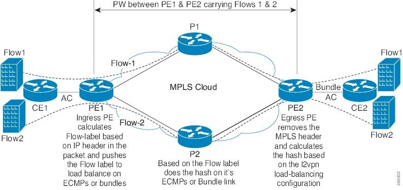
This example illustrates two flows distributing over ECMPs and bundle links.

Summary

The key components involved in the process are:

  • MPLS pseudowires (PWs): Virtual circuit connections that encapsulate customer traffic across the provider network.

  • ECMP paths: Multiple network paths with equal cost that allow traffic to be distributed for load sharing.

  • Bundle links: Groups of physical links that operate as a single logical connection, further enabling flow distribution within an ECMP path.

Workflow

These stages describe how MPLS PW traffic load balancing works.

  1. Topology establishment: The network is configured with ECMP paths and bundle links between ingress and egress provider edge (PE) routers.
  2. PW traffic initiation: Pseudowire tunnels are created, and multiple traffic flows (such as customer Ethernet frames) enter the provider network at the ingress PE.
  3. Flow hashing and selection: The ingress router uses flow-based hashing algorithms to select which ECMP path and which bundle link a specific flow follows.
  4. Traffic distribution: Individual flows are distributed across the available ECMP and bundle links, maximizing available bandwidth and enabling redundancy.
  5. Traffic egress: At the remote PE, packets are reassembled and forwarded to the customer edge.

Result

This process ensures that MPLS PW traffic is efficiently balanced across the network, improving resource utilization and providing better fault tolerance through the use of ECMP and bundle links.


Configure load balancing using control word and flow label

Set up load balancing for pseudowire traffic using both control word and flow label to optimize data distribution across multiple links.

Use this task to ensure traffic is efficiently balanced when deploying pseudowire-based Layer 2 VPNs. The control word and flow label enhance granular load distribution between endpoints.

Before you begin

  • Confirm that the pseudowire class and xconnect group are planned.

  • Ensure all prerequisite configurations and connectivity checks are complete.

Follow these steps to configure load balancing with control word and flow label:

Procedure

1.

Define the Layer 2 VPN pseudowire class and enable required features.

Example:

Router# configure
Router(config)# l2vpn
Router(config-l2vpn)# pw-class path1
Router(config-l2vpn-pwc)# encapsulation mpls
Router(config-l2vpn-pwc)# control-word
Router(config-l2vpn-pwc-mpls)# load-balancing flow-label both
2.

Set up the xconnect group and peer connection.

Example:

Router(config-l2vpn-pwc-mpls)# exit
Router(config-l2vpn-pwc)# exit
Router(config-l2vpn)# xconnect group grp1
Router(config-l2vpn-xc)# p2p vlan1
Router(config-l2vpn-xc-p2p)# interface HundredGigE0/0/0/1.2
Router(config-l2vpn-xc-p2p)# neighbor 10.0.0.2 pw-id 2000
Router(config-l2vpn-xc-p2p-pw)# pw-class path1
Router(config-l2vpn-xc-p2p-pw)# commit
3.

Add a point-to-point VLAN instance.

Example:

Router(config-l2vpn-xc)# p2p vlan1
Router(config-l2vpn-xc-p2p)# interface HundredGigE0/0/0/1.2
Router(config-l2vpn-xc-p2p)# neighbor 10.0.0.2 pw-id 2000
Router(config-l2vpn-xc-p2p-pw)# pw-class path1
Router(config-l2vpn-xc-p2p-pw)# commit
4.

Specify the neighbor and assign the pseudowire class.

Example:

Router(config-l2vpn-xc-p2p)# neighbor 10.0.0.2 pw-id 2000
Router(config-l2vpn-xc-p2p-pw)# pw-class path1
Router(config-l2vpn-xc-p2p-pw)# commit
5.

Review the running configuration to verify that settings are applied

Example:

l2vpn
 pw-class path1
  encapsulation mpls
   control-word
   load-balancing
    flow-label both
  !
 !
 xconnect group grp1
  p2p vlan1
   interface HundredGigE0/0/0/1.2
   neighbor ipv4 10.0.0.2 pw-id 2000
    pw-class path1
   !

This section shows the running configuration.

Load balancing using control word and flow label is successfully configured when the commit command completes and the running configuration reflects the desired setup.