L2VPN Configuration Guide for Cisco 8000 Series Routers, Cisco IOS XR Releases

PDF

L2VPN Configuration Guide for Cisco 8000 Series Routers, Cisco IOS XR Releases

G.8032 Ethernet ring protection switching

Want to summarize with AI?

Log in

Describes G.8032 Ethernet Ring Protection Switching, including operational principles, timers, single link failure protection and recovery, configuration procedures for ERPS profiles and instances, restrictions, and practical topology and interconnection examples.


G.8032 Ethernet ring protection switching is a resiliency protocol that

  • recovers from link or node failures in Ethernet ring topologies

  • uses RAPS messages to coordinate protection switching, and

  • helps maintain loop-free traffic forwarding in the ring.

Feature history

The feature history table lists release support for this feature.

Table 1. Feature History Table

Feature Name

Release Information

Feature Description

G.8032 Ethernet Ring Protection Switching

Release 26.2.1

Introduced in this release on: Modular Systems (8800 [LC ASIC: K100])(select variants only*)

*This feature is supported on Cisco 88-LC1-48Y8H-EM line cards.

G.8032 Ethernet Ring Protection Switching

Release 25.4.1

Introduced in this release on: Fixed Systems (8010 [ASIC: A100])(select variants only*)

*This feature is supported on:

  • 8011-32Y8L2H2FH

  • 8011-12G12X4Y-A/D

G.8032 Ethernet Ring Protection Switching

Release 25.1.1

Introduced in this release on: Fixed Systems (8010 [ASIC: A100])(select variants only*)

*This feature is supported on Cisco 8011-4G24Y4H-I routers.

G.8032 Ethernet Ring Protection Switching

Release 24.4.1

Introduced in this release on: Fixed Systems (8700) (select variants only*)

*The G.8032 Ethernet Ring Protection Switching functionality is now extended to the Cisco 8712-MOD-M routers.

G.8032 Ethernet Ring Protection Switching

Release 24.3.1

Introduced in this release on: Fixed Systems (8200 [ASIC: Q200, P100], 8700 [ASIC: P100])(select variants only*); Modular Systems (8800 [LC ASIC: Q100, Q200, P100])(select variants only*)

*The G.8032 Ethernet Ring Protection Switching functionality is now extended to:

  • 8212-48FH-M

  • 8711-32FH-M

  • 88-LC1-52Y8H-EM

  • 88-LC1-12TH24FH-E

G.8032 Ethernet Ring Protection Switching

Release 24.2.11

Introduced in this release on: Modular Systems (8800 [LC ASIC: P100]) (select variants only*)

Ethernet Ring Protection Switching (ERPS) protocol, defined in ITU-T G.8032, provides protection for Ethernet traffic in a ring topology, while ensuring that there are no loops within the ring at the Ethernet layer. The loops are prevented by blocking either a predetermined link or a failed link.

*This feature introduces the ethernet ring g8032 and ethernet ring g8032 profile commands.

This feature is supported on routers with the 88-LC1-36EH line cards.

ERPS recovery behavior

  • ERPS helps Ethernet ring topologies recover from link or node failures.

  • During a link failure, ERPS reroutes traffic to provide continuous connectivity.

  • ERPS simplifies network management and operates independently of control planes.
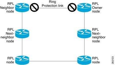

How G.8032 Ethernet ring protection switching works

Each Ethernet ring node uses two independent links to connect to its neighbors, forming a physical ring topology suitable for high availability. The ring avoids loops by blocking the RPL under normal operation.

Summary

The key components involved in the process are:

  • Ethernet ring node: A device connected to adjacent ring nodes using two independent links; participates in protection switching.

  • Ring protection link (RPL): A specific link designated to protect against loops in the Ethernet ring by being selectively blocked or unblocked.

  • Control protocols and messages (RAPS, CFM): Mechanisms that monitor link health, coordinate role actions, and trigger protection switching during failures or maintenance.

G.8032 Ethernet ring protection switching ensures loop-free, resilient connections in Ethernet ring topologies by coordinating node roles, protective mechanisms, and control protocols.

Workflow

Figure 1. G.8032 Ethernet Ring

The process involves these stages:

  1. Normal operation and loop avoidance:
    • The RPL is blocked by the RPL owner, preventing traffic loops on the ring while all other links carry traffic.
    • Nodes continuously send and monitor CFM Continuity Check Messages (CCM) to detect link health.
  2. Failure detection and switching:
    • When a link fails, nodes adjacent to the failure detect it using line status and CFM.
    • These nodes immediately block ports facing the failure and generate RAPS signal fail (SF) messages, which propagate through the ring.
    • Upon receiving RAPS SF, the RPL owner unblocks the RPL to restore traffic continuity.
  3. Recovery and reversion:
    • When the failed link is restored, its neighboring nodes send RAPS no request (NR) messages.
    • On receiving RAPS NR, the RPL owner blocks the RPL again and informs the ring via RAPS NR, root blocked (RB) messages.
    • All other nodes unblock any previously blocked ports, fully restoring the original topology.
  4. Administrative operations:
    • Force Switch (FS): Allows operators to force the blocking of a ring-port for immediate maintenance, even during existing failure conditions.
    • Manual Switch (MS): Allows manual port blocking unless an FS or SF condition is present. MS is overridden by new FS or SF events.
    • Clear command: Cancels existing FS or MS actions; used by the RPL owner to clear non-revertive modes.

Result

The Ethernet ring remains loop-free during normal and fault conditions, automatically restores traffic paths after failures, and allows administrative intervention for maintenance and optimization.


G.8032 ERPS timers

Types of ERPS timers

G.8032 Ethernet Ring Protection Switching (ERPS) uses several types of timers to avoid race conditions and unnecessary switching operations. These timers help ensure network stability and improve ring protection. The timers and their purposes are outlined below:

  • Delay timers: Used by the RPL Owner to verify that the network has stabilized before blocking the RPL.

  • Wait-to-Restore (WTR) timer: Activated after a signal failure (SF) condition to ensure the SF isn’t intermittent.

    • Operator-configurable.

    • Default time interval: 5 minutes (range: 1 to 12 minutes).

  • Wait-to-Block timer: Used after the FS/MS command to verify that no background condition exists.

    May be shorter than the Wait-to-Restore timer.

  • Guard timer:

    • Used by all nodes when changing state to block latent or outdated messages from causing unnecessary state changes.

    • Operator-configurable.

    • Default time interval: 500 ms (range: 10 to 2000 ms).

  • Hold-off timer:

    • Used by the underlying Ethernet layer to filter out intermittent link faults.

    • Operator-configurable.

    • Default time interval: 0 seconds (range: 0 to 10 seconds).

    • Faults are reported to the ring protection mechanism only if this timer expires.

ERPS operation during link failure

During a link failure, G.8032 ERPS performs one of the following actions to provide continuous connectivity:

  • Traffic rerouting: If ERPS is unable to recover from a link failure, it reroutes traffic.

    For more information, see Protection switching during single link failure section.

  • Wait to recover: ERPS waits to recover from the link failure to prevent unnecessary switching operations.

    For more information, see recovery from single link failure section.


Summary

The key components involved in the process are:

  • Ethernet ring nodes: Each node in the ring is identified by a unique node ID and port ID. Seven nodes (A to G) participate in the example discussed.

  • RPL owner and neighbor nodes: Node G is the RPL (Ring Protection Link) owner, and node A is the RPL neighbor. The RPL is the link between these two nodes.

  • Ring Automatic Protection Switching (RAPS) messages: Notification messages used for signaling link and node status during failures.

ERPS rapidly reroutes traffic to maintain network continuity when a single link fails in an Ethernet ring topology. The process is designed to minimize downtime and ensure reliable data transmission between ring nodes.

Workflow

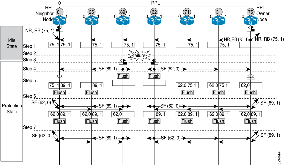
Figure 2. Protection switching during G.8032 single link failure

The process involves the following stages:

  1. The Ethernet ring operates normally, with traffic blocked at both ends of the RPL link between nodes A and G.
  2. A single link failure occurs between ring nodes C and D.
  3. Nodes C and D detect a local signal failure (SF) condition and, after a holdoff interval, block the failed port and flush their forwarding databases (FDB).
  4. Nodes C and D begin sending RAPS (SF) messages periodically, including node IDs and blocked port ring (BPR) pairs, on both ring ports. For example, node C sends an SF (89,1) message with its node ID and blocked port information.
  5. All nodes receiving a RAPS (SF) message perform an FDB flush. When the RPL owner (G) and neighbor (A) receive a RAPS (SF) message, each unblocks its end of the RPL and also flushes its FDB.
  6. All nodes receiving a second RAPS (SF) message repeat the FDB flush, due to the Node ID and BPR-based mechanism.
  7. Once the SF condition stabilizes, RAPS (SF) messages continue, but trigger no further actions.

Result

Traffic is rerouted through the now unblocked protection path, ensuring continued network operation while the failed link remains isolated until it is restored.


Summary

The key components involved in the process are:

  • Ethernet ring nodes (A–G): Network devices organized in a ring topology, each assigned unique node IDs and port IDs.

  • RPL owner node (G): The node responsible for managing the Ring Protection Link (RPL) and initiating recovery actions.

  • RPL neighbor node (A): The node adjacent to the RPL owner, working with the owner to control ring traffic and respond during recovery.

  • Ring protection link (RPL): The physical link between nodes A and G, where traffic is blocked at both ends to maintain ring integrity.

  • Guard timer and WTR timer: Mechanisms used to manage the timing of message transmissions and port recovery during the process.

  • RAPS messages (No Request and RB): Control messages exchanged between nodes to coordinate recovery and unblock ports.

ERPS restores the normal operation of ethernet rings affected by a single link failure by systematically managing blocked ring ports, timers, and messages among ring nodes to reestablish stable traffic flow.

Workflow

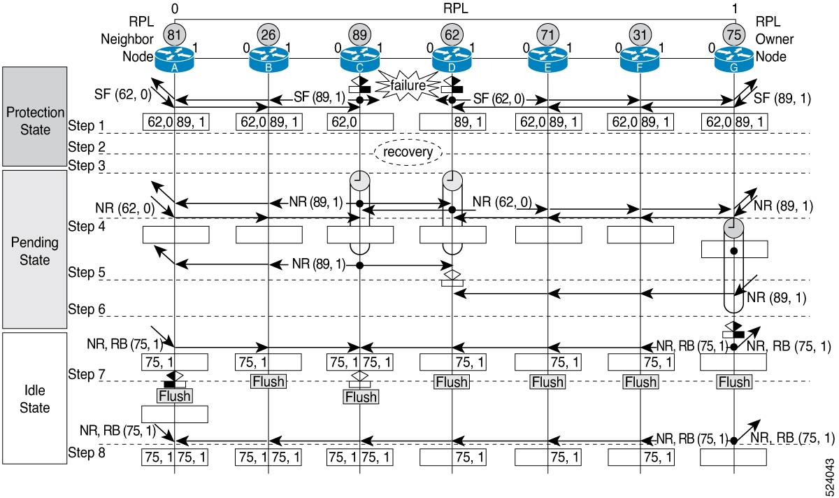
Figure 3. Single link failure recovery (Revertive operation)

The process involves these stages:

  1. The Ethernet ring consists of seven nodes (A–G), each assigned a unique node ID and port ID. Nodes A and G are designated as the RPL neighbor and owner, respectively, connected by the RPL.
  2. Traffic is initially blocked at both ends of the RPL to protect the ring.
  3. A link failure occurs between ring nodes C and D.
  4. After the failure is cleared, nodes C and D detect the clearing of the SF (Signal Failure) condition. They start the guard timer and transmit periodic RAPS No Request (NR) messages on both ring ports.
    Note
    The guard timer prevents reception of other RAPS messages during this period.
  5. When ring nodes receive RAPS (NR) messages, the node ID and Blocked Port Record (BPR) pair of the receiving port is deleted, and the RPL owner node (G) starts the Wait-To-Restore (WTR) timer.
  6. When the guard timer expires on nodes C and D, they accept new RAPS messages. Node D receives a RAPS (NR) message with a higher Node ID from node C and unblocks its non-failed ring port.
  7. After the WTR timer expires, the RPL owner node (G) blocks its end of the RPL, sends a RAPS (NR, RB) message with the node ID and BPR pair, and performs an FDB (Forwarding Database) flush.
  8. Node C receives the RAPS (NR, RB) message, removes the block on its ring ports, and stops sending RAPS (NR) messages. The RPL neighbor node (A) also receives the RAPS (NR, RB) message and blocks its end of the RPL. Nodes A to F flush their FDBs due to the Node ID and BPR mechanism.
  9. The ring resumes stable operation, with all ports unblocked and traffic restored.

Result

The ethernet ring returns to stable normal operation after the RPL owner blocks the RPL and all ring nodes flush their forwarding entries, ensuring network integrity and uninterrupted connectivity.


G.8032 Ethernet ring protection switching restrictions

Follow these requirements when using G.8032 Ethernet ring protection switching:

  • You must not configure G.8032 ERPS and CFM down-mep on the same sub-interface. If you enable it, then the router displays a syslog message, as shown in the following example:

    You must not configure G.8032 ERPS and CFM down-mep on the same sub-interface. If you enable both on the same sub-interface, the router displays a syslog message similar to the following example:

    Router# configure
    Router(config)# l2vpn
    Router(config-l2vpn)# ethernet ring g8032 test
    Router(config-l2vpn-erp)# port0 interface FourHundredGigE0/0/0/6
    Router(config-l2vpn-erp)# port1 interface FourHundredGigE0/0/0/10
    Router(config-l2vpn-erp)# instance 1
    Router(config-l2vpn-erp-inst)# profile test
    Router(config-l2vpn-erp-inst)# rpl port0 owner
    Router(config-l2vpn-erp-inst)# inclusion-list vlan-ids 1,100
    Router(config-l2vpn-erp-inst)# aps-channel
    Router(config-l2vpn-erp-inst-aps)# port0 interface FourHundredGigE0/0/0/6.1
    Router(config-l2vpn-erp-inst-aps)# port1 interface FourHundredGigE0/0/0/10.1
    
    Router(config)# interface FourHundredGigE0/0/0/6.1 l2transport
    Router(config-if)# encapsulation dot1q 1
    Router(config-if)# ethernet cfm
    Router(config-if-cfm)# mep domain domain1 service link1 mep-id 2
    
    %PLATFORM-SPITFIRE_CFM-3-G8032_VIOLATION : G8032 has been configured for interface FourHundredGigE0/0/0/6.1
    where CFM configuration exists. G8032 config is disabled.

    Instead configure the CFM down-mep on the main interface and configure the G.8032 ERPS on the sub-interface.

  • Linecards and fixed routers with Q100 and Q200 based Silicon One ASICs do not support G.8032 Ethernet ring protection switching.


Configure G.8032 Ethernet ring protection switching

G.8032 Ethernet ring protection switching is a network resiliency protocol that

  • enables rapid switching between alternate communication paths when a failure occurs

  • uses ERPS profiles, instances, parameters, and TCN propagation to control ring behavior, and

  • leverages CFM to monitor ring links and bridge domains to define the Layer 2 topology.

Additional reference information

To configure the G.8032 operation, you have to configure ERPS and CFM separately as follows:

  • To configure G.8032 Ethernet Ring Protection Switching, configure ERPS and CFM as follows:

    • ERPS configuration:

      • Set the ERPS profile, instance, parameters, and TCN propagation.

      • Designate a (sub)interface as the APS channel.

      • Assign a (sub)interface for CFM monitoring.

    • Check whether an interface is an RPL link and, if so, indicate its RPL node type.

    For configuration details, see:

    • Configure ERPS profile

    • Configure an ERPS instance

    • Configure ERPS parameters

    • Configure TCN propagation

  • CFM configuration:

    • Configure CFM with EFD to monitor the ring links.

    • For configuration details, see Configuring CFM MEP.

      Note

      Each monitored link requires a Maintenance Association (MEP) configured.

  • Bridge domains:

    • Create bridge domains to define the Layer 2 topology.

    • RAPS channels are managed in a dedicated management bridge domain, separate from data bridge domains.

  • Behavior characteristics (optional):

    Apply attributes to the ERPS instance that differ from default values.


Configure an ERPS profile

Configure an ERPS profile to enable G.8032 Ethernet ring protection, set timing parameters, and define ring behavior.

Perform this task when you need to improve ring resilience and prevent unnecessary switching using ERPS profiles.

Before you begin

Confirm that you have planned the ERPS profile name and timing values.

Follow these steps to configure an ERPS profile:

Procedure

1.

Configure a new G.8032 ERPS profile.

Example:

Router# configure
Router(config)# Ethernet ring g8032 profile p1

Enables G.8032 ring mode, and enters G.8032 configuration submode.

2.

Sets the hold-off timer.

Example:

Router(config-g8032-ring-profile)# timer hold-off 5

Specifies a time interval (in seconds) for the guard, hold-off, and wait-to-restore timers.

The hold-off timer prevents unnecessary switching due to short-lived failures on the ring.

3.

Specify a non-revertive ring instance.

Example:

Router(config-g8032-ring-profile)# non-revertive
Router(config-g8032-ring-profile)# commit

Enables the router to use the current path until an administrator manually reverts to the original path.

You successfully configure an ERPS profile. The configuration is committed, and verification output shows the expected state.


Configure an ERPS instance for a bridge domain

Set up an ERPS instance to provide Ethernet ring protection switching for a bridge domain in your Layer 2 VPN.

Use this task when you want to configure Ethernet ring protection switching (G.8032) for enhanced network redundancy in a Layer 2 VPN environment.

Before you begin

  • Plan your bridge domain and ring port details.

  • Ensure you have access to Layer 2 VPN configuration mode on your router.

Follow these steps to configure an ERPS instance for a bridge domain:

Procedure

1.

Configure the layer 2 VPN with a bridge group and bridge domain for R-APS channels.

Example:

Router# configure
Router(config)# l2vpn
Router(config-l2vpn)# bridge group cisco
Router(config-l2vpn-bg)# bridge-domain bd1
2.

Assign interfaces to each bridge domain.

For R-APS channels (ports 0 and 1):

Example:

Router(config-l2vpn-bg-bd)# interface GigabitEthernet 0/0/0/0.1
Router(config-l2vpn-bg-bd)# interface GigabitEthernet 0/0/0/1.1
3.

Configure a bridge domain for data traffic and assign an interface to a bridge domain.

Example:

Router(config-l2vpn-bg)# bridge-domain bd2
Router(config-l2vpn-bg-bd)# interface GigabitEthernet 0/0/0/0.10
4.

Configure an ethernet ring and define an ERPS instance

Example:

Router(config-l2vpn)# ethernet ring g8032 r1
Router(config-l2vpn-erp)# instance 1
5.

Set up an ERPS profile.

Example:

Router(config-l2vpn-erp-instance)# profile p1

Specifies associated Ethernet ring G.8032 profile.

6.

Specify the RPL port and designate it as a neighbor.

Example:

Router(config-l2vpn-erp-instance)# rpl port0 neighbor

Specifies one ring port on the local node as RPL owner, neighbor, or next-neighbor.

7.

Configure VLAN inclusion for the ERPS instance, enable Automatic Protection Switching (APS) channel, and set the priority level for the APS protocol.

Example:

Router(config-l2vpn-erp-instance)# inclusion-list vlan-ids e-g
Router(config-l2vpn-erp-instance)# aps-channel
Router(config-l2vpn-erp-instance-aps)# level 5
8.

Assign ports to the G.8032 APS channel interface:

For port0:

Example:

Router(configl2vpn-erp-instance-aps)# port0 interface GigabitEthernet 0/0/0/0.1

For port1:

Example:

Router(config-l2vpn-erp-instance-aps)# port1 interface GigabitEthernet 0/0/0/1.1

Once your configuration is committed, the ERPS instance is active and can be verified to ensure expected state and protection switching behavior.


Configure ERPS parameters

Set up ERPS parameters to safeguard ring links and configure monitoring.

Perform this task when you need to enable ring protection and monitoring on an existing ERPS instance.

Before you begin

Confirm that the ERPS instance exists in your device configuration.

Follow these steps to configure ERPS parameters:

Procedure

1.

Configure an ethernet ring in L2VPN configuration mode.

Example:

Router# configure
Router(config)# l2vpn
Router(config-l2vpn)# ethernet ring g8032 r1

Enters L2VPN configuration mode, enables G.8032 ring mode, and enters G.8032 configuration submode.

2.

For each ring port you wish to protect:

  1. Enable G.8032 ERPS for the specified port.

    Example:

    Router(config-l2vpn-erp)# port0 interface GigabitEthernet 0/0/0/0
  2. Specify a port to monitor the G.8032 ERPS and detect ring link failure.

    Example:

    Router(config-l2vpn-erp-port0)# monitor port0 interface 0/0/0/0.5
  3. Exit from port configuration submode.

    Example:

    Router(config-l2vpn-erp-port0)# exit
  4. Repeat for additional ports as needed.

    For example,

    Example:

    Router(config-l2vpn-erp)# port1 interface GigabitEthernet 0/0/0/1
    Router(config-l2vpn-erp-port1)# monitor port1 interface 0/0/0/1.5
    Router(config-l2vpn-erp-port1)# exit
3.

Configure a set of VLAN IDs that should not be protected by ERPS.

Example:

Router(config-l2vpn-erp)# exclusion-list vlan-ids a-d
4.

Configure the ethernet ring G.8032 as an open ring.

Example:

Router(config-l2vpn-erp)# open-ring

ERPS parameters are configured successfully. Verification output should show the ring instance and monitored ports in the desired state.


Configure TCN propagation

Enable topology change notification (TCN) propagation for an ERPS instance to ensure network topology changes are propagated correctly between network rings.

TCN propagation ensures that changes detected within one ring are communicated to associated major rings or protocols, improving convergence and loop prevention in complex ring-based networks.

Before you begin

  • Confirm that the ERPS instance is configured.

  • Ensure the relevant bridge domain is configured.

Follow these steps to configure TCN propagation for an ERPS instance:

Procedure

Enable TCN propagation in L2VPN configuration mode.

Example:

Router# configure
Router(config)# l2vpn
Router(config-l2vpn)# tcn-propagation
Router(config-l2vpn)# commit

TCN propagation is enabled for the ERPS instance. Verification commands display the updated state reflecting the configuration.


Configure CFM MEP

Enable continuous monitoring and rapid rerouting of traffic in Ethernet rings using CFM MEPs in networks running G.8032 (ERPS).

CFM MEPs and G.8032 Ethernet Ring Protection Switching work together to monitor the Ethernet ring's health. If a ring link fails, Ethernet Fault Detection (EFD) automatically shuts down the affected port and reroutes traffic through an alternate path, maintaining network resilience.

Before you begin

Ensure all CFM domains, services, and ring interfaces are defined and planned.

Follow these steps to configure CFM MEP for G.8032 monitoring:

Procedure

1.

Configure a CFM domain and service.

Example:

Router# configure
Router(config)# ethernet cfm
Router(config-cfm)# domain dom23to24 level 6
Router(config-cfm-domain)# service ser23to24 down-meps
2.

Configure continuity checks to enable fault detection.

Example:

Router(config-cfm-svc)# continuity-check interval 10s
3.

Configure a MEP crosscheck on the main interface to detect failures and reroute traffic.

Example:

Router(config-cfm-svc)# mep crosscheck
Router(config-cfm-svc-xcheck)# mep-id 3
Router(config-cfm-svc-xcheck)# exit
4.

Configure Ethernet Fault Detection (EFD) for failure detection and rerouting.

Example:

Router(config-cfm-svc)# efd
5.

Configure CFM MEP on the sub-interface.

Example:

Router# configure terminal
Router(config)# interface Gigabiteethernet0/0/0/0.5
Router(config-if)# ethernet cfm
Router(config-if-cfm)# mep domain dom23to24 service ser23to24 mep-id 4

The CFM MEP configuration enables continuous monitoring of the Ethernet ring. If a link failure occurs, the router shuts down the affected port and automatically reroutes traffic, ensuring service continuity. You can verify the configuration and operational state using verification commands relevant to your platform.


G.8032 Ethernet ring protection switching example

This sample configuration illustrates the elements that a complete G.8032 configuration includes:

# Configure the ERP profile characteristics if ERPS instance behaviors are non-default.
ethernet ring g8032 profile ERP-profile
  timer wtr 60
  timer guard 100
  timer hold-off 1
  non-revertive


# Configure the ERPS instance under L2VPN
l2vpn
  ethernet ring g8032 RingA
    port0 interface g0/0/0/0
    port1 interface g0/1/0/0
    instance 1
      description BD2-ring
      profile ERP-profile
      rpl port0 owner
      vlan-ids 10-100
      aps channel
        level 3
        port0 interface g0/0/0/0.1
        port1 interface g1/1/0/0.1

# Set up the bridge domains
bridge group ABC
    bridge-domain BD2
      interface Gig 0/0/0/0.2
      interface Gig 0/1/0/0.2
      interface Gig 0/2/0/0.2

    bridge-domain BD2-APS
      interface Gig 0/0/0/0.1
      interface Gig 1/1/0/0.1

# EFPs configuration
interface Gig 0/0/0/0.1 l2transport
  encapsulation dot1q 5

interface Gig 1/1/0/0.1 l2transport
  encapsulation dot1q 5

interface g 0/0/0/0.2 l2transport
  encapsulation dot1q 10-100

interface g 0/1/0/0.2 l2transport
  encapsulation dot1q 10-100

interface g 0/2/0/0.2 l2transport
  encapsulation dot1q 10-100

G.8032 interconnection node example

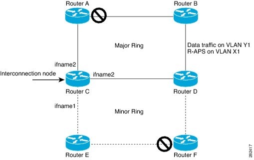
This example shows you how to configure an interconnection node. The following figure illustrates an open ring scenario.

Summary

The key components involved in the process are:

  • Interconnection node (Router C in this scenario): Serves as the connecting point between different segments of the Ethernet ring.

  • Ethernet ring controller: Manages the G.8032 ring state and triggers protection switching when failures are detected.

  • Network interfaces: Carry VLAN-tagged traffic segments and are configured with specific encapsulation settings to support the ring topology.

G.8032 interconnection nodes support network resiliency in Ethernet ring topologies by enabling open ring architectures, which help in rapid protection switching and fault recovery.

Workflow

Figure 4. Open ring scenario - interconnection node

The process involves these stages:

  1. Prepare network interfaces: Identify and configure physical and subinterfaces on the interconnection node required for the ring.
  2. Assign encapsulation to interfaces: Apply appropriate VLAN tags (e.g., dot1q X1, Y1) to distinguish different traffic segments across interfaces.
  3. Define the Ethernet ring instance: Create the G.8032 Ethernet ring with required parameters, including ring name, interface assignments, and open-ring settings.
  4. Set instance parameters: Include the VLAN ID inclusion list, enable the rapid protection switching channel (APS), and establish bridge domains for both APS control and data traffic.
  5. Apply bridging configuration: Map the relevant interfaces into bridge domains associated with the APS channel and regular traffic domains.

Result

The interconnection node is active within an open G.8032 Ethernet ring, supporting fast protection switching and loop-free operation in the event of link or node failures.

The configuration steps referenced in the process correspond to this example:

interface <ifname1.1> l2transport
	encapsulation dot1q X1
interface <ifname1.10> l2transport
	encapsulation dot1q Y1
interface <ifname2.10> l2transport
	encapsulation dot1q Y1
interface <ifname3.10> l2transport
	encapsulation dot1q Y1
l2vpn
ethernet ring g8032 <ring-name>
      port0 interface <main port ifname1>
      port1 interface none #? This router is connected to an interconnection node
      open-ring #? Mandatory when a router is part of an open-ring
      instance <1-2>
         inclusion-list vlan-ids  X1-Y1
         aps-channel
           Port0 interface <ifname1.1>
           Port1 none #? This router is connected to an interconnection node
	bridge group bg1
	   bridge-domain bd-aps#? APS-channel has its own bridge domain
	      <ifname1.1> #? There is only one APS-channel at the interconnection node
	   bridge-domain bd-traffic #? Data traffic has its own bridge domain
	      <ifname1.10>
	      <ifname2.10>
	      <ifname3.10>

G.8032 node of an open ring example

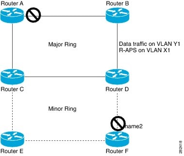
This example shows you how to configure the node part of an open ring. The following figure illustrates an open ring scenario.

Summary

The key components involved in the process are:

  • G.8032 node (router F): Acts as the part of the open ring, requiring specific configuration for participation in ERPS.

  • Ethernet interfaces: Physical and logical interfaces used for ring and traffic, each assigned unique VLAN identifiers.

  • Ring logic and protection features: Settings such as open ring mode, inclusion lists, RPL ownership, APS-channel, and bridge groups, which facilitate redundancy and protection.

Configuring a G.8032 node in an open ring topology enables redundancy and resiliency by implementing Ethernet Ring Protection Switching (ERPS). This process involves multiple interfaces, VLAN configurations, and logical ring parameters to ensure continuous service and rapid recovery from failures.

Workflow

Figure 5. Open ring scenario

The process involves these stages:

  1. Interface configuration: Configure the relevant physical and logical interfaces required for ring traffic and APS.
  2. Ethernet ring G.8032 setup: Enable open ring mode (mandatory for open ring topology), set the ring instance, inclusion list for VLANs, and assign the RPL owner.
  3. APS-channel configuration: Define APS channel ports for monitoring and switching.
  4. Bridge group and domain setup: Configure bridge groups with bridge-domain for APS channel interfaces and bridge-domain for regular ring data traffic interfaces.
  5. Verification: Validate that the configuration matches the network topology for correct open ring and protection switching operation.

Result

Upon completing these configuration stages, the G.8032 node functions as an effective part of the open ring topology, enabling ERPS-based protection, redundancy, and seamless data traffic continuity in the network.

The configuration steps referenced in the process correspond to this example:

interface <ifname1.1> l2transport
	encapsulation dot1q X1
interface <ifname2.1> l2transport
	encapsulation dot1q X1
interface <ifname1.10> l2transport
	encapsulation dot1q Y1
interface <ifname2.10> l2transport
	encapsulation dot1q Y1
l2vpn
   ethernet ring g8032 <ring-name>
      port0 interface <main port ifname1>
      port1 interface <main port ifname2>
      open-ring #? Mandatory when a router is part of an open-ring
      instance <1-2>
         inclusion-list vlan-ids  X1-Y1
	     rpl port1 owner #? This node is RPL owner and <main port ifname2> is blocked
         aps-channel
           port0 interface <ifname1.1>
           port1 interface <ifname2.1>
	bridge group bg1
	   bridge-domain bd-aps#? APS-channel has its own bridge domain
	      <ifname1.1>
	      <ifname2.1>
	   bridge-domain bd-traffic #? Data traffic has its own bridge domain
	      <ifname1.10>
	      <ifname2.10>