L2VPN Configuration Guide for Cisco 8000 Series Routers, Cisco IOS XR Releases

PDF

L2VPN Configuration Guide for Cisco 8000 Series Routers, Cisco IOS XR Releases

CFM on VPLS

Want to summarize with AI?

Log in

Outlines CFM implementation on VPLS, detailing components, supported offload types, timer values, operational restrictions, process flows, and configuration instructions for Ethernet connectivity fault management.


A CFM on VPLS feature is a service-level OAM feature that

  • monitors a Layer 2 VPN running VPLS

  • uses continuity-check and Y.1731 functions to detect and isolate faults, and

  • reports end-to-end ethernet connectivity issues.

Table 1. Feature history table

Feature Name

Release Information

Feature Description

CFM on VPLS

Release 25.4.1

Introduced in this release on: Fixed Systems (8010 [ASIC: A100])(select variants only*)

*This feature is now supported on:

  • 8011-12G12X4Y-A

  • 8011-12G12X4Y-D

CFM on VPLS

Release 25.1.1

Introduced in this release on: Fixed Systems (8010 [ASIC: A100])(select variants only*)

*This feature is supported on Cisco 8011-4G24Y4H-I routers.

CFM on VPLS

Release 24.4.1

Introduced in this release on: Fixed Systems (8200 [ASIC: P100], 8700 [ASIC: P100, K100])(select variants only*); Modular Systems (8800 [LC ASIC: Q100, P100])(select variants only*)

The CFM on VPLS feature is now extended to:

  • 8712-MOD-M

  • 8212-48FH-M

  • 8711-32FH-M

  • 88-LC1-52Y8H-EM

  • 88-LC1-12TH24FH-E

  • 88-LC1-36EH

CFM on VPLS

Release 7.3.2

This feature helps you monitor and manage a Layer 2 VPN running VPLS. It does so by providing proactive network management, enabling fault detection and isolation, and reporting end-to-end ethernet connectivity issues.


CFM components and protocols for VPLS

The following are the key components of CFM:

  • Maintenance Domain (MD): A management space for administering a network. A maintenance domain is owned and operated by a single entity and defined by the set of ports internal to the domain and at its boundary.

  • Maintenance Association/Service (MA): Identifies a service that can be uniquely located within the maintenance domain. The maintenance association monitors the connectivity of a particular service instance in an MD.

  • Maintenance Point: A demarcation point on an interface that participates in CFM within a maintenance domain. Two classes of maintenance points exist: Maintenance End Point (MEP) and Maintenance Intermediate Point.

  • Maintenance End Point (MEP): Located at the edge of a domain, MEPs define the boundary for CFM messages. MEPs drop all lower-level frames and forward higher-level frames. MEPs are defined per maintenance domain level and service.

    The following MEPs are used:

    • Down MEP: Outward-facing MEPs that communicate through the wire, using the port MAC address. Often used for services spanning a single Layer 2 link.

    • Up MEP: Inward-facing MEPs that communicate through the bridge relay function. Up MEPs send and receive CFM frames at their level through the relay function, commonly used for services across multiple switches with end-to-end connections via xconnect Layer 2 AC interfaces.

CFM protocols used in VPLS include:

  • Continuity Check protocol: Used for fault detection and notification, carrying the status of the port on which the MEP is configured.

  • Loopback protocol: Used for fault verification.

  • Linktrace protocol: Used for path discovery and fault isolation.

For more information about CFM, see the Configuring Ethernet OAM chapter in the Interface and Hardware Component Configuration Guide for Cisco 8000 Series Routers.


Restrictions for CFM on VPLS

You must follow these restrictions when configuring CFM on VPLS:

  • Do not configure Up MEPs and Down MEPs on the same interface.

  • Multiple MEPs of the same direction are supported on the same interface.

  • Maintenance Intermediate Point is not supported on any interface.

  • MEPs on bundle member interfaces are limited to maintenance domain level 0.

  • Software offload is supported only on bundle member Down MEPs.

  • CFM does not work on Layer 2 subinterfaces with default encapsulation.


Offload types and supported CCM timers for CFM on VPLS interfaces

Offload types and CCM timer

Table 2. Feature history table

Feature Name

Release Information

Feature Description

CFM Hardware Offload

Release 7.9.1

CFM Hardware offloading allows to implement connectivity and fault monitoring for physical and bundle interfaces, using continuity check messages (CCM). This feature helps to detect network failure with short CCM intervals, which enables the router to recover from the failure without dropping the packets.

Depending on where the continuity check messages are processed, offload is categorized into software offload, hardware offload, and non-offload. CCM intervals are the intervals in which CCMs are sent and received.

Depending on where the continuity check messages are processed, the offload method is categorized as software offload, hardware offload, or non-offload. CCM intervals define how frequently CCMs are sent and received.

Table 3. Supported CCM timers by offload type

Interface Type

Offload Type

Supported CCM Timers

Physical Interfaces and Subinterfaces

Non-offload

  • 1 sec

  • 10 sec

  • 1 min

  • 10 min

Physical Interfaces and Subinterfaces

Hardware offload

  • 3.3 ms

  • 10 ms

Bundle Members

Non-offload

1 sec; 10 sec; 1 min; 10 min

  • 1 sec

  • 10 sec

  • 1 min

  • 10 min

Bundle Members

Software offload

100 ms

Bundle Interfaces and Subinterfaces

Non-offload

  • 1 sec

  • 10 sec

  • 1 min

  • 10 min

Bundle Interfaces and Subinterfaces

Hardware offload

  • 3.3 ms

  • 10 ms


How CFM on VPLS works

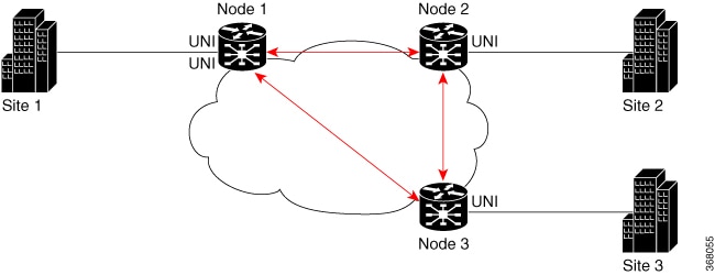
This process uses a full-mesh VPLS topology to monitor connectivity between provider edge routers with CFM.

Summary

The key components involved in CFM on VPLS are:

  • PE routers: Participate in the VPLS mesh and deliver the bridged service.

  • CFM continuity checks: Monitor connectivity between the nodes.

  • Maintenance end points (MEPs): Exchange CFM messages across the VPLS service.

CFM on VPLS verifies end-to-end connectivity across a VPLS mesh by sending continuity-check messages between routers participating in the service.

Workflow

CFM on VPLS involves these stages:

  1. The PE routers form a VPLS mesh in which each node participates in the same bridged service.
  2. The routers configure CFM continuity checks and MEP relationships for the VPLS service.
  3. The MEPs exchange CFM messages so the routers can monitor connectivity and detect service faults across the mesh.

Result

The VPLS service provides monitored end-to-end connectivity between the PE routers, ensuring detection and management of service faults.


Configure CFM for VPLS services

Set up CFM for VPLS services, including continuity check, MEP cross-check, interface CFM, and verification of MEP states.

CFM is used to monitor and maintain Ethernet services. For details on CFM configuration and troubleshooting, see the Configuring Ethernet OAM chapter in the Interface and Hardware Component Configuration Guide for Cisco 8000 Series Routers.

Before you begin

Follow these steps to configure CFM for VPLS services:

Procedure

1.

Enable CFM continuity check for the VPLS service.

Example:

Router# configure
Router# ethernet cfm
Router(config-cfm# domain vpls_bgp level 3 id null
Router(config-cfm-dmn)# service vpls_bgp_1 bridge group vpls bridge-domain vpls-1 id number 1000
Router(config-cfm-dmn-svc)# continuity-check interval 10s
2.

Configure MEP cross-check and logging.

Example:

Router(config-cfm-dmn-svc)# mep crosscheck
Router(config-cfm-dmn-svc-xcheck)# mep crosscheck
Router(config-cfm-dmn-svc-xcheck)# exit
Router(config-cfm-dmn-svc)# log continuity-check errors
Router(config-cfm-dmn-svc)# log continuity-check mep changes
Router(config-cfm-dmn-svc)# commit
3.

Enable CFM on the interface and configure the Up MEP.

Example:

Router# configure
Router(config)# interface HundredGigE0/0/0/2/0.1000 l2transport
Router(config-subif)# encapsulation dot1q 1000
Router(config-subif)# ethernet cfm
Router(config-if-cfm)# mep domain vpls_bgp service vpls_bgp_1 mep-id 1
Router(config-if-cfm-mep)# commit
4.

Review the running configuration.

Example:

ethernet cfm
 domain vpls_bgp level 3 id null
  service vpls_bgp_1 bridge group vpls bridge-domain vpls-1 id number 1000
   continuity-check interval 10s
   mep crosscheck
    mep-id 8191
   !
   log continuity-check errors
   log continuity-check mep changes
  !
!
!
interface HundredGigE0/0/0/2/0.1000 l2transport
 encapsulation dot1q 1000
 ethernet cfm
  mep domain vpls_bgp service vpls_bgp_1 mep-id 1
 !
5.

Use show ethernet cfm peer meps , show ethernet cfm peer meps detail , and show ethernet cfm local meps verbose commands to verify peer and local MEP status.

Example:

Router(PE1)# show ethernet cfm peer meps
Flags:
 > - Ok
 I - Wrong interval
 R - Remote Defect received
 V - Wrong level
 L - Loop (our MAC received)
 T - Timed out
 C - Config (our ID received)
 M - Missing (cross-check)
 X - Cross-connect (wrong MAID)
 U - Unexpected (cross-check)
 * - Multiple errors received
 S - Standby
Domain id_no (level 3) , Service id_no_vpws_1
Up MEP on TenGigE0/0/0/2/0.1 MEP-ID 1
================================================================================
St ID MAC Address Port Up/Downtime CcmRcvd SeqErr RDI Error
-- ----- -------------- ------- ----------- --------- ------ ----- -----
> 8191 b0c5.3cff.c0c1 Up 00:01:26 9 0 4 0

Router(PE1)# show ethernet cfm peer meps detail
Domain id_no (level 3), Service id_no_vpws_1
Up MEP on TenGigE0/0/0/2/0.1 MEP-ID 1
================================================================================
Peer MEP-ID 8191, MAC b0c5.3cff.c0c1
CFM state: Ok, for 00:01:44
Port state: Up
CCMs received: 11
Out-of-sequence: 0
Remote Defect received: 4
Wrong level: 0
Cross-connect (wrong MAID): 0
Wrong interval: 0
Loop (our MAC received): 0
Config (our ID received): 0
Last CCM received 00:00:04 ago:
Level: 3, Version: 0, Interval: 10s
Sequence number: 8495, MEP-ID: 8191
MAID: NULL, UINT: 1
Chassis ID: Local: Eyrie; Management address: 'Not specified'
Port status: Up, Interface status: Up

Router(PE1)# show ethernet cfm local meps verbose
Domain id_no (level 3), Service id_no_vpws_1
Up MEP on TenGigE0/0/0/2/0.1 MEP-ID 1
================================================================================
Interface state: Up
MAC address: d46a.355c.b808
Peer MEPs: 1 up, 0 with errors, 0 timed out (archived)
Cross-check errors: 0 missing, 0 unexpected
CCM generation enabled: Yes, 10s (Remote Defect detected: No)
AIS generation enabled: No Sending AIS: No Receiving AIS: No
Sending CSF: No Receiving CSF: No
Packet Sent Received
------ ---------- ---------------------------------------------------------
CCM 8508 24 (out of seq: 0)

CFM continuity checking is successfully configured for the VPLS service. Verification commands confirm the expected state for peer and local MEPs.