Describes pseudowire functionality within VPLS bridge domains, covering configuration, statistics monitoring, forwarding instances, transport types, control-word operations, and flow-aware transport for optimized load balancing.
A pseudowire in a VPLS bridge domain is a point-to-point connection that
connects pairs of PE routers
emulates Ethernet service over an MPLS core, and
encapsulates the service in a common MPLS format.
Multiple pseudowires within a bridge domain are supported. However, multiple pseudowires to the same destination within the same bridge domain are not supported.
Configure a pseudowire under a bridge domain
Configure a pseudowire under a bridge domain to establish Layer 2 connectivity between routers.
This task is commonly used in MPLS or carrier Ethernet scenarios where a pseudowire needs to be associated with a specific bridge domain.
Before you begin
Follow these steps to configure the pseudowire exactly as shown in the source example.
The bridge domain includes the configured pseudowire neighbor and pw-id.
Check ingress pseudowire statistics
Configure pseudowire statistics for ingress pseudowires, reload the slots, and verify aggregate and unicast counters.
Use the hw-module profile l2fib pw-stats command to enable pseudowire statistics. After you enable pseudowire statistics, you must reload all slots for the configuration to take effect.
Pseudowire statistics are not supported on line cards based on Q100 Silicon.
Before you begin
Follow these steps to enable and inspect pseudowire statistics.
Procedure
Enable pseudowire statistics and reload the slots so the configuration takes effect.
Only aggregate and unicast statistics are supported for ingress PW disposition. Statistics resources are limited, and enabling statistics on pseudowires impacts forwarding performance.
Use the show hw-module profile l2fib command to check the hardware profile before and after the reload.
Example:
Before the reload:
Router# show hw-module profile l2fib
--------------------------------------------------------------
Knob                          Status          Applied   Action
--------------------------------------------------------------
PW-Stats                      Configured      No        Reload
BD-Flush-Convergence          Unconfigured    N/A       None

After the reload:
Router# show hw-module profile l2fib
--------------------------------------------------------------
Knob                          Status          Applied   Action
--------------------------------------------------------------
PW-Stats                      Configured      Yes       None
BD-Flush-Convergence          Unconfigured    N/A       None
Inspect the aggregate and unicast statistics for ingress pseudowires.
Example:
Router# show l2vpn forwarding bridge-domain detail location 0/RP0/CPU0 | inc "state:Nbor|XC ID|received"
    XC ID: 0x1
      packets: received 2081 (multicast 0, broadcast 2081, unknown unicast 0, unicast 0), sent 998
      bytes: received 266368 (multicast 0, broadcast 266368, unknown unicast 0, unicast 0), sent 127744
    XC ID: 0x2
      packets: received 0 (multicast 0, broadcast 0, unknown unicast 0, unicast 0), sent 3079
      bytes: received 0 (multicast 0, broadcast 0, unknown unicast 0, unicast 0), sent 394112
    XC ID: 0xa0000001
      packets: received 998 (unicast 0), sent 1996
      bytes: received 145708 (unicast 0), sent 307384
Pseudowire statistics are enabled and the aggregate and unicast counters are visible in the forwarding output.
Virtual forwarding instances in VPLS
Key features of VFIs in VPLS
Virtual forwarding instances (VFIs) are virtual bridge ports used in VPLS networks to interconnect the pseudowire mesh for each VPLS instance. VFIs perform native bridging functions required for packet forwarding, including learning and aging of MAC addresses, and directing data based on destination MAC addresses.
Provide virtual bridge ports within the VPLS instance.
Perform native bridging functions such as forwarding based on destination MAC addresses, source MAC address learning, and aging.
Enable PE routers to make packet-forwarding decisions by referencing the VFI associated with a particular VPLS instance.
Support connection of multiple attachment circuits belonging to a given VPLS.
Here is the sample configuration for a VFI under the bridge domain.
VPLS pseudowires support several transport types, enabling flexible and scalable network designs for multipoint Layer 2 VPN services. Each transport type provides different underlying mechanisms for establishing connectivity across provider networks.
The supported transport types for VPLS pseudowires are:
LDP: Utilizes LDP for signaling and establishing pseudowire tunnels.
Segment routing: Leverages segment routing for simplified path management and traffic engineering.
LDP over TE: Combines LDP signaling with TE tunnels for enhanced path control.
BGP-LU for inter-AS C topology: Uses BGP with Label Unicast to support inter-AS connections in C topology scenarios.
Supported pseudowire types and VLAN tag transport behavior
Ethernet port mode (Type 5)
These pseudowire types are supported for MPLS:
Both ends of the pseudowire connect to Ethernet ports and transport a complete ethernet trunk.
Frames received on a main interface or subinterface are transported by the ingress PE.
This mode eliminates the need for dummy VLAN tags and reduces overhead.
Frame tagging is no longer necessary.
The ingress PE does not remove incoming VLAN tags; they are transported over the pseudowire.
Type 4 inserts an extra dummy tag with VLAN 0 onto the frame, which is removed at the remote end.
Allows service providers to segregate traffic per customer using VLANs.
Each VLAN on a customer-to-provider link can be configured as a separate Layer 2 VPN connection.
Pseudowire Mode
VC Type
VLAN Tag Handling
Dummy Tag Required
Use Cases
Ethernet Port Mode
5
Original tags are removed; the entire trunk is transported as-is.
No
Full trunk transport between Ethernet ports (Port-to-Port).
VLAN Mode
4
VLAN tags are preserved; a dummy tag (VLAN 0) may be added for frame prioritization.
Yes (if only 1 tag); not needed with >1 tag
Segregation of traffic per VLAN; Layer 2 VPN per specific VLAN.
Key considerations:
VLAN-based VC type 4 pseudowires transport VLAN tags by pushing a dummy tag at the ingress when only a single tag is present.
If multiple VLAN tags are pushed, a dummy tag is unnecessary—they are transported directly.
The dummy tag (if added) is removed on the remote router before egress.
Mixing Type 4 and Type 5 pseudowires in the same Virtual Forwarding Instance (VFI) is not supported: all pseudowires in a VFI must be of the same type.
Pseudowire control-word
A pseudowire control-word is an optional 4-byte protocol field that
sits between the MPLS label stack and the Layer 2 payload in a pseudowire packet
carries generic and Layer 2 payload-specific information, and
enables sequencing, assists identification for load balancing, and supports Ethernet pseudowire packet handling.
The control-word can pad small packets, carry Layer 2 control bits, preserve sequence, support load balancing, and indicate payload fragmentation.
Functions of the pseudowire control-word
The pseudowire control-word serves several key functions in AToM packet transport:
Padding small packets: If an AToM packet is below the minimum length, the frame is padded to meet Ethernet requirements. The control-word includes a length field that helps the egress PE router determine whether padding was added and remove it before forwarding.
Carrying control bits: The control-word transports control bits from the Layer 2 header of the protocol being carried.
Sequencing transported frames: The control-word preserves the sequence of frames. Each packet sent over the pseudowire receives an incrementing sequence number, starting with 1 and continuing to 65535. Out-of-sequence packets are dropped; packets are never re-ordered.
Load balancing: The control-word enables correct identification of Ethernet PW packets and prevents misordering caused by equal-cost multipath (ECMP) path selection. The control-word, inserted after the MPLS label, separates payload from MPLS and carries Layer 2 control bits and supports sequencing.
Fragmentation signaling:
The control-word indicates payload fragmentation status using two bits:
00: Unfragmented
01: First fragment
10: Last fragment
11: Intermediate fragment
Configure a pseudowire control-word
Enable the control-word for a bridge-domain pseudowire by using a pseudowire class.
The control-word keyword is inserted immediately after the MPLS label to separate the payload from the MPLS label over a pseudowire.
Before you begin
Follow these steps to configure the pseudowire control-word.
Procedure
Create a pseudowire class that enables the control-word.
The pseudowire uses a pseudowire class with the control word enabled, ensuring correct payload separation after the MPLS label.
Flow-aware transport pseudowires
A flow-aware transport pseudowire is a pseudowire transport behavior that
identifies individual flows within a pseudowire
inserts a flow label as the lowermost label in the packet, and
allows routers to use that flow label to load balance traffic across equal-cost or bundled core paths.
Table 1. Feature history table
Feature Name
Release Information
Feature Description
Load Balancing using Flow Aware Transport Pseudowire
Release 26.3.1
Introduced in this release on: Modular Systems (8800 [LC ASIC: K100])(select variants only*)
*This feature is supported on Cisco 88-LC1-48Y8H-EM line cards.
Load Balancing using Flow Aware Transport Pseudowire
Release 24.4.1
Introduced in this release on: Fixed Systems (8700) (select variants only*)
*The load balancing with FAT PW functionality is now extended to the Cisco 8712-MOD-M routers.
Load Balancing using Flow Aware Transport Pseudowire
Release 24.3.1
Introduced in this release on: Fixed Systems (8200 [ASIC: Q200, P100], 8700 [ASIC: P100])(select variants only*); Modular Systems (8800 [LC ASIC: Q100, Q200, P100])(select variants only*)
*The load balancing with FAT PW functionality is now extended to:
8212-48FH-M
8711-32FH-M
88-LC1-52Y8H-EM
88-LC1-12TH24FH-E
Load Balancing using Flow Aware Transport Pseudowire
Release 24.2.11
Introduced in this release on: Modular Systems (8800 [LC ASIC: P100]) (select variants only*)
This feature enhances network performance by distributing traffic flows evenly across multiple pseudowires, preventing congestion and optimizing bandwidth usage. This method identifies and labels individual traffic flows, allowing for precise load distribution in MPLS networks.
*This functionality is now extended to routers with the 88-LC1-36EH line cards.
Flow-aware transport pseudowire attributes and ECMP load balancing
Flow-aware transport pseudowires (FAT PW) enhance load balancing for traffic carried over pseudowires. Routers typically load balance traffic using the lowermost label in the label stack. In standard pseudowires, this label remains the same for all flows, which can cause uneven traffic distribution and asymmetric load balancing.
Key characteristics of flow-aware transport pseudowires:
FAT PW identifies individual packet flows within a pseudowire.
FAT PW creates a flow label based on each packet flow entering the pseudowire.
FAT PW inserts the flow label as the lowermost label in the packet.
Routers use the flow label to make load-balancing decisions.
FAT PW enables routers to identify individual flows within a pseudowire and leverage that flow information for more effective load balancing. This capability is especially valuable in core networks using equal-cost multipaths (ECMP).
How flow-aware transport pseudowires work
Routers typically load balance pseudowire traffic using the lowermost label in the label stack. Since this label is uniform across all flows on a pseudowire, it can lead to uneven and asymmetric load balancing. Flow-aware transport pseudowires mitigate these issues by adding flow labels that differentiate packets, improving traffic distribution.
Summary
The key components involved in the process are:
Ingress PE: Identifies individual packet flows and generates a unique flow label for each flow entering the pseudowire.
Flow label: Provides entropy based on source and destination MAC and IP addresses, enabling differentiation among flows.
Core routers: Use the flow label to load balance traffic across ECMP or bundled paths.
Egress PE: Discards the flow label before forwarding the traffic.
Flow-aware transport pseudowires enable more efficient traffic distribution by adding entropy to packet flows. This ensures that routers can better identify individual flows and distribute them evenly across ECMP and bundled links.
Workflow
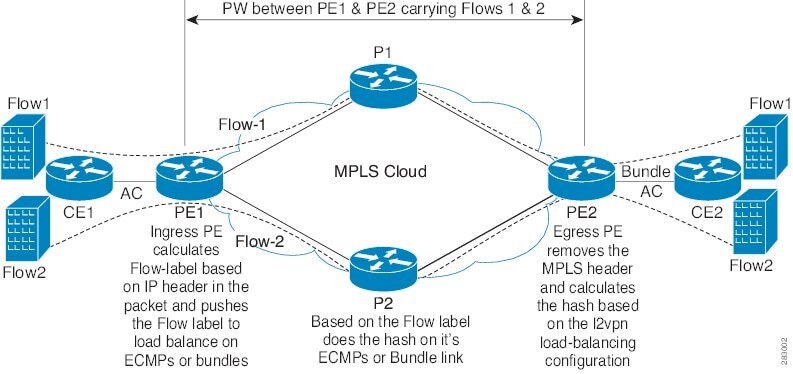
Figure 1. FAT PW with two flows distributing over ECMPs and bundle links
Flow-aware transport pseudowires involve these stages:
Flow identification and label generation: The ingress PE examines packets entering the pseudowire, identifies individual flows, and derives a flow label based on their source and destination MAC and IP addresses.
Label insertion: The ingress PE inserts the flow label after the VC label and before the control word (when present), setting the end-of-stack bit on the flow label.
Traffic load balancing and label removal: Core routers use the flow label and other packet information to distribute traffic across ECMP paths and link bundles. The egress PE discards the flow label before forwarding the traffic onward.
Result
Pseudowire traffic gains additional entropy, allowing for more even and efficient distribution across the core network. Note that MPLS OAM ping traffic cannot use flow aware transport pseudowires since MPLS OAM does not support the flow label.
Configure a flow-aware transport pseudowire
Enable load balancing across ECMP and bundle links by applying a flow label to a transport pseudowire.
Routers typically perform load balancing based on the lowermost label in the label stack, which remains the same for all flows over a given pseudowire. Adding a flow label enables distribution of traffic across multiple ECMP or bundled paths in the core.
You cannot send MPLS OAM ping traffic over a FAT pseudowire, because there is no flow-label support for MPLS OAM.
Before you begin
Follow these steps to enable load balancing with a flow label under the pseudowire class.
Procedure
Create a pseudowire class that enables the flow label.