L2VPN Configuration Guide for Cisco 8000 Series Routers, Cisco IOS XR Releases

PDF

L2VPN Configuration Guide for Cisco 8000 Series Routers, Cisco IOS XR Releases

Pseudowire modes over MPLS

Want to summarize with AI?

Log in

Explains available pseudowire over MPLS service modes, including Ethernet port, VLAN, VLAN passthrough, redundancy, and Inter-AS modes; outlines configuration steps and requirements for each mode, including redundancy and manual switchover procedures.


A pseudowire mode over MPLS is a transport option that

  • defines how the provider edge router handles Ethernet frames and VLAN tags across the pseudowire

  • supports Ethernet port mode over a virtual connection type 5 pseudowire, and

  • supports VLAN mode and VLAN passthrough mode over virtual connection type 4 pseudowires.

Ethernet port mode

Ethernet port mode is a pseudowire over MPLS mode that

  • connects both ends of a pseudowire to Ethernet ports

  • tunnels the port over a virtual connection type 5 pseudowire, and

  • transports VLAN manipulation over the type 5 pseudowire, whether tagged or untagged.

Feature history

Table 1. Feature History Table

Feature Name

Release Information

Feature Description

Pseudowire VC Type 5

Release 26.2.1

Introduced in this release on: Modular Systems (8800 [LC ASIC: K100])(select variants only*);

*This feature is supported on Cisco 88-LC1-48Y8H-EM line cards.

Pseudowire VC Type 5

Release 25.1.1

Introduced in this release on: Fixed Systems (8700 [ASIC: K100], 8010 [ASIC: A100])(select variants only*)

*This feature is supported on:

  • 8011-4G24Y4H-I

  • 8712-MOD-M

Pseudowire VC Type 5

Release 24.4.1

Introduced in this release on: Fixed Systems(8200, 8700);Modular Systems (8800 [ASIC: P100]) (select variants only*)

*This feature is now supported on:

  • 8212-32FH-M

  • 8711-32FH-M

  • 88-LC1-12TH24FH-E

  • 88-LC1-52Y8H-EM

  • 88-LC1-36EH

Pseudowire VC Type 5

Release 7.3.15

With this feature, Ethernet port mode is supported for pseudowire over MPLS. The virtual connection (VC) type 5 is known as an Ethernet port-based PW. In this mode, both ends of a pseudowire are connected to Ethernet ports and allow a complete ethernet trunk to be transported. The ingress PE transports frames received on a main interface or subinterface. This feature nullifies the need for a dummy tag and reduces overhead. In addition, frame tagging is no longer necessary.

Ethernet port mode packet flow

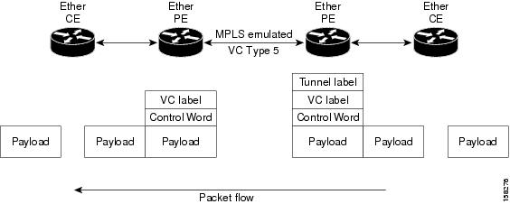
The ingress provider edge router transports frames received on a main interface.

The ingress provider edge router can also transport frames after subinterface tags are removed.

Subinterface tags are removed when the packet is received on a subinterface.

Figure 1. Ethernet port mode packet flow

Configure Ethernet port mode

Use this task to configure Ethernet port mode for pseudowire over MPLS.

Ethernet port mode uses a virtual connection type 5 pseudowire to create a Layer 2 VPN across MPLS.

Before you begin

Confirm the provider edge interfaces and neighbor pseudowire IDs before you configure the service.

Procedure

1.

Configure Ethernet port mode on PE1.

Example:

Router# configure
Router(config)# l2vpn
Router(config-l2vpn)# xconnect group grp1
Router(config-l2vpn-xc)# p2p xc1
Router(config-l2vpn-xc-p2p)# interface HundredGigE0/0/0/1.2
Router(config-l2vpn-xc-p2p)# neighbor 10.0.0.11 pw-id 222
Router(config-l2vpn-xc-p2p-pw)# commit
2.

Configure Ethernet port mode on PE2.

Example:

Router# configure
Router(config)# l2vpn
Router(config-l2vpn)# xconnect group grp1
Router(config-l2vpn-xc)# p2p xc1
Router(config-l2vpn-xc-p2p)# interface HundredGigE0/1/0/3.2
Router(config-l2vpn-xc-p2p)# neighbor 10.0.0.13 pw-id 222
Router(config-l2vpn-xc-p2p-pw)# commit
3.

Review the Ethernet port mode running configuration.

Example:

PE1 configuration
l2vpn
 xconnect group grp1
  p2p xc1
   interface HundredGigE0/0/0/1.2
   neighbor 10.0.0.11 pw-id 222

PE2 configuration
l2vpn
 xconnect group grp1
  p2p xc1
   interface HundredGigE0/1/0/3.2
   neighbor 10.0.0.13 pw-id 222
4.

Use the show l2vpn xconnect group grp1 detail command to verify the Ethernet port mode configuration.

Example:

Router# show l2vpn xconnect group grp1 detail
Group grp1, XC xc1, state is up; Interworking none
  AC: HundredGigE0/0/0/1.2, state is up
    Type VLAN; Num Ranges: 1
    VLAN ranges: [2, 2]
    MTU 1504; XC ID 0x840006; interworking none
  PW: neighbor 10.0.0.11, PW ID 222, state is up ( established )
    Encapsulation MPLS, protocol LDP
    Source address 10.0.0.13
    PW type Ethernet, control word disabled, interworking none
    PW backup disable delay 0 sec
    PW Status TLV in use
      MPLS         Local                          Remote
      Label        16026                          16031
      Interface    HundredGigE0/0/0/1.2           HundredGigE0/1/0/3.2
      MTU          1504                           1504
      PW type      Ethernet                       Ethernet

The PW type Ethernet value indicates a virtual connection type 5 pseudowire.

The Ethernet port mode pseudowire is configured, and verification output reports PW type Ethernet.


VLAN mode

VLAN mode is a pseudowire over MPLS mode that

  • configures each VLAN on a CE-to-PE link as a separate Layer 2 VPN connection by using virtual connection type 4

  • transports a VLAN tag over the pseudowire by pushing a dummy tag at the attachment-circuit ingress, and

  • removes the dummy tag before egress on the remote router when the dummy tag has been added.

Feature history

Table 2. Feature History Table

Feature Name

Release Information

Feature Description

Pseudowire VC Type 4

Release 25.4.1

Introduced in this release on: Fixed Systems (8010 [ASIC: A100])(select variants only*)

  • 8011-32Y8L2H2FH

  • 8011-12G12X4Y-A/D

Pseudowire VC Type 4

Release 25.1.1

Introduced in this release on: Fixed Systems (8700 [ASIC: K100], 8010 [ASIC: A100])(select variants only*)

  • 8011-4G24Y4H-I

  • 8712-MOD-M

Pseudowire VC Type 4

Release 24.4.1

Introduced in this release on: Fixed Systems(8200, 8700);Modular Systems (8800 [ASIC: P100]) (select variants only*)

  • 8212-32FH-M

  • 8711-32FH-M

  • 88-LC1-12TH24FH-E

  • 88-LC1-52Y8H-EM

  • 88-LC1-36EH

Pseudowire VC Type 4

Release 7.3.15

With this feature, VLAN mode is supported for pseudowire over MPLS. A virtual connection (VC) type 4 is the VLAN-based PW. The ingress PE does not remove the incoming VLAN tags that are to be transported over the PW. VC type 4 inserts an extra dummy tag with VLAN 0 onto the frame which is removed on the other side. This mode helps the service provider to segregate traffic for each customer based on the VLAN.

VLAN mode packet flow

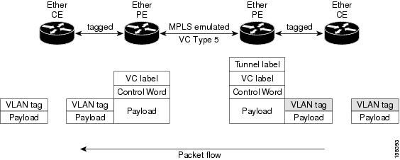
The Ethernet provider edge router associates an internal VLAN tag to the Ethernet port.

The internal VLAN tag switches traffic internally from the ingress port to the pseudowire.

The provider edge router removes the internal VLAN tag before moving traffic into the pseudowire.

Figure 2. VLAN mode packet flow

At the egress VLAN provider edge router, the provider edge router associates a VLAN tag to the frames coming out of the pseudowire.

The provider edge router sends traffic on an Ethernet trunk port after it switches the traffic internally.

Note

Because the port is in trunk mode, the VLAN provider edge router does not remove the VLAN tag.

It forwards the frames through the port with the added tag.


VLAN mode TPID handling

Account for Tag Protocol Identifier (TPID) handling whenever VLAN mode adds or removes a dummy VLAN tag. Follow these requirements:

  • On the pseudowire imposition provider edge router, the pushed TPID of the dummy VLAN tag uses the innermost popped VLAN tag TPID.

  • If no VLAN tag is popped on the ingress Layer 2 interface, the Tag Protocol Identifier on the dummy VLAN is 0x8100.

  • On the disposition provider edge router, egress VLAN tag push copies the TPID of the dummy VLAN tag to the innermost pushed VLAN tag.

  • If no egress VLAN push is configured on the egress Layer 2 interface, the dummy VLAN tag is discarded.


Configure VLAN mode for pseudowire over MPLS

Use this task to configure VLAN mode for pseudowire over MPLS.

VLAN mode uses a pseudowire class with MPLS encapsulation and transport-mode VLAN.

Before you begin

Review the VLAN mode Tag Protocol Identifier handling requirement before you configure the service.

Procedure

1.

Configure VLAN mode under the pseudowire class and xconnect.

Example:

Router# configure
Router(config)# l2vpn
Router(config-l2vpn)# pw-class VLAN
Router(config-l2vpn-pwc)# encapsulation mpls
Router(config-l2vpn-pwc-mpls)# transport-mode vlan
Router(config-l2vpn-pwc-mpls)# exit
Router(config-l2vpn-pwc)# exit
Router(config-l2vpn)# xconnect group grp1
Router(config-l2vpn-xc)# p2p xc1
Router(config-l2vpn-xc-p2p)# neighbor 10.0.0.11 pw-id 222
Router(config-l2vpn-xc-p2p-pw)# pw-class VLAN
Router(config-l2vpn-xc-p2p-pw)# commit
2.

Review the VLAN mode running configuration.

Example:

l2vpn
 pw-class VLAN
  encapsulation mpls
   transport-mode vlan
  !
 !
 xconnect group grp1
  p2p xc1
   neighbor 10.0.0.11 pw-id 222
    pw-class VLAN
   !
  !
 !
!
3.

Use the show l2vpn xconnect group grp1 detail | i " PW type" command to verify the VLAN mode configuration.

Example:

Router# show l2vpn xconnect group grp1 detail | i " PW type"
PW type Ethernet VLAN, control word disabled, interworking none
      PW type      Ethernet VLAN                  Ethernet VLAN

The PW type Ethernet VLAN value indicates a virtual connection type 4 pseudowire.

The VLAN mode pseudowire is configured, and the verification output reports PW type Ethernet VLAN.


VLAN passthrough mode

VLAN passthrough mode is a VLAN transport mode that

  • negotiates a virtual connection type 4 Ethernet VLAN pseudowire

  • transports what comes out of the attachment circuit after VLAN tag manipulation, and

  • leaves at least one VLAN tag on the frame without adding a dummy VLAN 0 tag.

The transport mode vlan passthrough command is configured under the pseudowire class to enable VLAN passthrough mode.


Pseudowire redundancy

A pseudowire redundancy is a backup-path mechanism that

  • establishes a secondary pseudowire to support the primary pseudowire

  • enables the provider edge router to reroute traffic to the secondary pseudowire upon primary failure, and

  • allows automatic restoration of the primary path once it becomes available.

The primary pseudowire fails when the provider edge router fails or when a network outage occurs.

Feature history

The feature history table lists release support for pseudowire redundancy.

Table 3. Feature History Table

Feature Name

Release Information

Feature Description

Pseudowire Redundancy

Release 26.2.1

Introduced in this release on: Modular Systems (8800 [LC ASIC: K100])(select variants only*);

*This feature is supported on Cisco 88-LC1-48Y8H-EM line cards.

Pseudowire Redundancy

Release 24.4.1

Introduced in this release on: Fixed Systems (8700) (select variants only*)

* The PW redundancy functionality is now extended to the Cisco 8712-MOD-M routers.

Pseudowire Redundancy

Release 24.3.1

Introduced in this release on: Fixed Systems (8200 [ASIC: Q200, P100], 8700 [ASIC: P100])(select variants only*); Modular Systems (8800 [LC ASIC: Q100, Q200, P100])(select variants only*)

* The PW redundancy functionality is now extended to:

  • 8212-48FH-M

  • 8711-32FH-M

  • 88-LC1-52Y8H-EM

  • 88-LC1-12TH24FH-E

Pseudowire Redundancy

Release 24.2.11

Introduced in this release on: Modular Systems (8800 [LC ASIC: P100]) (select variants only*)

Pseudowire redundancy enhances network reliability by providing backup paths for pseudowires in case of a failure, ensuring continuous data transmission. This feature allows for the establishment of primary and secondary pseudowires, which can automatically switch traffic to the backup if the primary path fails.

* This functionality is now extended to routers with the 88-LC1-36EH line cards.

Pseudowire redundancy

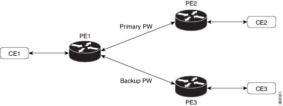
The pseudowire redundancy feature allows you to configure a redundant pseudowire that backs up the primary pseudowire. When the primary pseudowire fails, the PE router switches to the redundant pseudowire. You can elect to have the primary pseudowire resume operation after it becomes functional. The primary pseudowire fails when the PE router fails or when there is a network outage.

Figure 3. Pseudowire redundancy

Forcing a manual switchover to the backup pseudowire

Use the l2vpn switchover command in EXEC mode to manually force the router to switch to the backup pseudowire or return to the primary pseudowire. The command performs these functions:

  • Forces the router to switch to the backup pseudowire.

  • Switches back to the primary pseudowire using the same command.

  • Initiates manual switchover only if the specified peer is available.

  • Moves the cross-connect to a fully active state when executed.


Configure pseudowire redundancy

Set up pseudowire redundancy for a Layer 2 VPN cross-connect to ensure continuous connectivity in case of pseudowire failure.

The configuration defines a primary pseudowire and a backup pseudowire under the point-to-point cross-connect on provider edge (PE) routers.

Before you begin

  • 2000 active and 2000 backup PWs are supported.

  • Only MPLS Label Distribution Protocol is supported.

Procedure

1.

Configure the primary pseudowire and backup pseudowire on PE1.

Example:

Router# configure
Router(config)# l2vpn
Router(config-l2vpn)# xconnect group XCON1
Router(config-l2vpn-xc)# p2p xc1
Router(config-l2vpn-xc-p2p)# interface HundredGigE0/1/0/0.1
Router(config-l2vpn-xc-p2p)# neighbor ipv4 172.16.0.1 pw-id 1
Router(config-l2vpn-xc-p2p-pw)# backup neighbor 192.168.0.1 pw-id 1
Router(config-l2vpn-xc-p2p-pw-backup)# commit
2.

Configure the pseudowire on PE2.

Example:

Router# configure
Router(config)# l2vpn
Router(config-l2vpn)# xconnect group XCON1
Router(config-l2vpn-xc)# p2p xc1
Router(config-l2vpn-xc-p2p)# interface HundredGigE0/1/0/0.1
Router(config-l2vpn-xc-p2p)# neighbor ipv4 10.0.0.1 pw-id 1
Router(config-l2vpn-xc-p2p-pw)# commit
3.

Configure the pseudowire on PE3.

Example:

Router# configure
Router(config)# l2vpn
Router(config-l2vpn)# xconnect group XCON1
Router(config-l2vpn-xc)# p2p xc1
Router(config-l2vpn-xc-p2p)# interface HundredGigE0/1/0/0.1
Router(config-l2vpn-xc-p2p)# neighbor ipv4 10.0.0.1 pw-id 1
Router(config-l2vpn-xc-p2p-pw)# commit
4.

Use the show l2vpn xconnect group XCON_1 command to verify that the configured pseudowire redundancy is up.

Router (PE1)# show l2vpn xconnect group XCON_1
Legend: ST = State, UP = Up, DN = Down, AD = Admin Down, UR = Unresolved,
        SB = Standby, SR = Standby Ready, (PP) = Partially Programmed

XConnect                   Segment 1                       Segment 2
Group      Name       ST   Description            ST       Description            ST
------------------------   -----------------------------   -----------------------------
XCON_1     XCON1_P2P2 UP   Hu0/1/0/0.1            UP       172.16.0.1     1000   UP
                                                           Backup
                                                           192.168.0.1     1000   SB
-----------------------------------------------------------------------------------


Router (PE2)# show l2vpn xconnect group XCON_1
Tue Jan 17 15:36:12.327 UTC
Legend: ST = State, UP = Up, DN = Down, AD = Admin Down, UR = Unresolved,
        SB = Standby, SR = Standby Ready, (PP) = Partially Programmed

XConnect                   Segment 1                       Segment 2
Group      Name       ST   Description            ST       Description            ST
------------------------   -----------------------------   -----------------------------
XCON_1     XCON1_P2P2 UP   BE100.1                UP       10.0.0.1     1000   UP
----------------------------------------------------------------------------------------


Router (PE3)# show l2vpn xconnect group XCON_1
Tue Jan 17 15:38:04.785 UTC
Legend: ST = State, UP = Up, DN = Down, AD = Admin Down, UR = Unresolved,
        SB = Standby, SR = Standby Ready, (PP) = Partially Programmed

XConnect                   Segment 1                       Segment 2
Group      Name       ST   Description            ST       Description            ST
------------------------   -----------------------------   -----------------------------
XCON_1     XCON1_P2P2 DN   BE100.1                UP       10.0.0.1     1000   SB
----------------------------------------------------------------------------------------

Router# show l2vpn xconnect summary
Number of groups: 3950
Number of xconnects: 3950
  Up: 3950  Down: 0  Unresolved: 0 Partially-programmed: 0
  AC-PW: 3950  AC-AC: 0  PW-PW: 0 Monitor-Session-PW: 0
Number of Admin Down segments: 0
Number of MP2MP xconnects: 0
  Up 0 Down 0
  Advertised: 0 Non-Advertised: 0
Number of CE Connections: 0
  Advertised: 0 Non-Advertised: 0
Backup PW:
  Configured   : 3950
  UP           : 0
  Down         : 0
  Admin Down   : 0
  Unresolved   : 0
  Standby      : 3950
  Standby Ready: 0
Backup Interface:
  Configured   : 0
  UP           : 0
  Down         : 0
  Admin Down   : 0
  Unresolved   : 0
  Standby      : 0

Inter-AS modes

Inter-AS mode is a peer-to-peer mode for L2VPN pseudowire that

  • allows VPNs to operate through multiple providers or multidomain networks using Layer 2 VPN cross-connect

  • enables VPLS autodiscovery to function across multiple Border Gateway Protocol autonomous systems, and

  • provides end-to-end VPN connectivity across different geographical locations.

An autonomous system is a single network or group of networks controlled by a common system administration group and using a single, clearly defined routing protocol.

Feature history

The feature history table lists release support for Inter-AS mode for L2VPN pseudowire.

Table 4. Feature History Table

Feature Name

Release Information

Feature Description

Inter-AS Mode for L2VPN Pseudowire

Release 26.2.1

Introduced in this release on: Modular Systems (8800 [LC ASIC: K100])(select variants only*);

*This feature is supported on Cisco 88-LC1-48Y8H-EM line cards.

Inter-AS Mode for L2VPN Pseudowire

Release 25.4.1

Introduced in this release on: Fixed Systems (8010 [ASIC: A100])(select variants only*)

This feature is supported on:

  • 8011-32Y8L2H2FH

  • 8011-12G12X4Y-A/D

Inter-AS Mode for L2VPN Pseudowire

Release 25.1.1

Introduced in this release on: Fixed Systems (8010 [ASIC: A100])(select variants only*)

*This feature is supported on Cisco 8011-4G24Y4H-I routers.

Inter-AS Mode for L2VPN Pseudowire

Release 24.4.1

Introduced in this release on: Fixed Systems (8700) (select variants only*)

* The Inter-AS mode functionality is now extended to the Cisco 8712-MOD-M routers.

Inter-AS Mode for L2VPN Pseudowire

Release 24.3.1

Introduced in this release on: Fixed Systems (8200 [ASIC: Q200, P100], 8700 [ASIC: P100])(select variants only*); Modular Systems (8800 [LC ASIC: Q100, Q200, P100])(select variants only*)

* The Inter-AS mode functionality is now extended to:

  • 8212-48FH-M

  • 8711-32FH-M

  • 88-LC1-52Y8H-EM

  • 88-LC1-12TH24FH-E

Inter-AS Mode for L2VPN Pseudowire

Release 24.2.11

Introduced in this release on: Modular Systems (8800 [LC ASIC: P100]) (select variants only*)

* The Inter-AS mode functionality is now extended to routers with the 88-LC1-36EH line cards.

Inter-AS Mode for L2VPN Pseudowire

Release 7.3.15

Inter-AS is a peer-to-peer type that allows VPNs to operate through multiple providers or multi-domain networks using L2VPN cross-connect. This mode allows VPLS autodiscovery to operate across multiple BGP autonomous systems and enables service providers to offer end-to-end VPN connectivity over different geographical locations.

Inter-AS deployment context

As VPNs grow, their requirements expand. In some cases, VPNs must reside on different autonomous systems in different geographic areas. Some VPNs also need to extend across multiple service providers. Regardless of complexity and location, the connection between autonomous systems must be seamless.

Ethernet over MPLS supports both single and multiple autonomous system topologies:

  • In the single autonomous system topology, the pseudowire resides within the same autonomous system and connects provider edge routers at both ends of the point-to-point Ethernet over MPLS cross-connects.

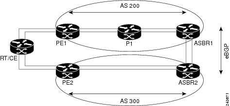
  • In multiple autonomous system topologies, provider edge routers can reside in two different autonomous systems using internal and external Border Gateway Protocol peering

Figure 4. Ethernet over MPLS over Inter-AS basic double autonomous system topology

Configure Inter-AS mode

Configure Inter-AS mode across provider edge routers to enable Layer 2 VPN pseudowire deployment using MPLS Label Distribution Protocol, BGP autodiscovery, and signaling.

This procedure enables key protocols and configuration parameters required for Layer 2 VPN service across autonomous systems, including route target planning and provider edge (PE) router setup.

Before you begin

Confirm that the autonomous system design and provider edge router addresses are planned before you configure Inter-AS mode.

Procedure

1.

Configure Inter-AS mode on PE1.

Example:

Router# configure
Router(config)# mpls ldp
Router(config-ldp)# router-id 10.0.0.1
Router(config-ldp)# interface HundredGigE0/2/0/3
Router(config-ldp-if)# exit
Router(config-ldp)# router bgp 100
Router(config-bgp)# bgp router-id 10.0.0.1
Router(config-bgp)# address-family l2vpn vpls-vpws
Router(config-bgp-af)# neighbor 172.16.0.1
Router(config-bgp-nbr)# remote-as 200
Router(config-bgp-nbr)# update-source Loopback0
Router(config-bgp-nbr)# address-family l2vpn vpls-vpws
Router(config-bgp-nbr-af)# exit
Router(config-bgp-nbr)# exit
Router(config-bgp)# exit
Router(config)# l2vpn
Router(config-l2vpn)# xconnect group gr1
Router(config-l2vpn-xc)# mp2mp mp1
Router(config-l2vpn-xc-mp2mp)# vpn-id 100
Router(config-l2vpn-xc-mp2mp)# l2-encapsulation vlan
Router(config-l2vpn-xc-mp2mp)# autodiscovery bgp
Router(config-l2vpn-xc-mp2mp-ad)# rd auto
Router(config-l2vpn-xc-mp2mp-ad)# route-target 192.0.2.2:100
Router(config-l2vpn-xc-mp2mp-ad)# signaling-protocol bgp
Router(config-l2vpn-xc-mp2mp-ad-sig)# ce-id 1
Router(config-l2vpn-xc-mp2mp-ad-sig-ce)# interface HunGigE0/1/0/1.1 remote-ce-id 2
Router(config-l2vpn-xc-mp2mp-ad-sig-ce)# interface HunGigE0/1/0/1.1 remote-ce-id 3
Router(config-l2vpn-xc-mp2mp-ad-sig-ce)# commit
2.

Configure Inter-AS mode on PE2.

Example:

Router# configure
Router(config)# mpls ldp
Router(config-ldp)# router-id 172.16.0.1
Router(config-ldp)# interface HundredGigE0/3/0/0
Router(config-ldp-if)# exit
Router(config-ldp)# router bgp 100
Router(config-bgp)# bgp router-id 172.16.0.1
Router(config-bgp)# address-family l2vpn vpls-vpws
Router(config-bgp-af)# neighbor 10.0.0.1
Router(config-bgp-nbr)# remote-as 100
Router(config-bgp-nbr)# update-source Loopback0
Router(config-bgp-nbr)# address-family l2vpn vpls-vpws
Router(config-bgp-nbr-af)# exit
Router(config-bgp-nbr)# exit
Router(config-bgp)# exit
Router(config)# l2vpn
Router(config-l2vpn)# xconnect group gr1
Router(config-l2vpn-xc)# mp2mp mp1
Router(config-l2vpn-xc-mp2mp)# vpn-id 100
Router(config-l2vpn-xc-mp2mp)# l2-encapsulation vlan
Router(config-l2vpn-xc-mp2mp)# autodiscovery bgp
Router(config-l2vpn-xc-mp2mp-ad)# rd auto
Router(config-l2vpn-xc-mp2mp-ad)# route-target 192.0.2.2:100
Router(config-l2vpn-xc-mp2mp-ad)# signaling-protocol bgp
Router(config-l2vpn-xc-mp2mp-ad-sig)# ce-id 2
Router(config-l2vpn-xc-mp2mp-ad-sig-ce)# interface HunGigE0/1/0/2.1 remote-ce-id 3
Router(config-l2vpn-xc-mp2mp-ad-sig-ce)# interface HunGigE0/1/0/2.2 remote-ce-id 1
Router(config-l2vpn-xc-mp2mp-ad-sig-ce)# commit
3.

Review the running configuration.

Inter-AS mode is configured on both provider edge routers, enabling MPLS Label Distribution Protocol, Border Gateway Protocol autodiscovery, and Layer 2 VPN signaling for pseudowire services.

PE1 configuration
mpls ldp
 router-id 10.0.0.1
 interface HundredGigE0/2/0/3
 !
router bgp 100
 bgp router-id 10.0.0.1
 address-family l2vpn vpls-vpws
 neighbor 172.16.0.1
  remote-as 200
  update-source Loopback0
  address-family l2vpn vpls-vpws
!
l2vpn
 xconnect group gr1
  mp2mp mp1
    vpn-id 100
    l2-encapsulation vlan
    autodiscovery bgp
     rd auto
     route-target 192.0.2.2:100
     signaling-protocol bgp
      ce-id 1
       interface HunGigE0/1/0/1.1 remote-ce-id 2
       interface HunGigE0/1/0/1.2 remote-ce-id 3

PE2 configuration
mpls ldp
 router-id 172.16.0.1
 interface HundredGigE0/3/0/0
 !
router bgp 100
 bgp router-id 172.16.0.1
 address-family l2vpn vpls-vpws
 neighbor 10.0.0.1
  remote-as 100
  update-source Loopback0
  address-family l2vpn vpls-vpws
!
l2vpn
 xconnect group gr1
  mp2mp mp1
    vpn-id 100
    l2-encapsulation vlan
    autodiscovery bgp
     rd auto
     route-target 192.0.2.2:100
     signaling-protocol bgp
      ce-id 2
       interface HunGigE0/1/0/2.1 remote-ce-id 3
       interface HunGigE0/1/0/2.2 remote-ce-id 1