L2VPN Configuration Guide for Cisco 8000 Series Routers, Cisco IOS XR Releases

PDF

L2VPN Configuration Guide for Cisco 8000 Series Routers, Cisco IOS XR Releases

Pseudowire headend

Want to summarize with AI?

Log in

Details pseudowire headend interface architecture, highlighting hardware requirements, interface behaviors, benefits, supported topologies, traffic flow types, encapsulation and decapsulation processes, configuration guidelines, restrictions, and procedures for setup.


A Pseudowire headend interface is a virtual interface that

  • terminates access pseudowires into a Layer 3 VRF, a global Layer 3 domain, or a Layer 2 domain

  • integrates legacy Layer 2 services into IP or MPLS packet-switched networks, and

  • emulates attachment-circuit behavior on the service provider edge.

Feature history

The feature history table lists release support for this feature.

Table 1. Feature History Table

Feature Name

Release Information

Feature Description

Pseudowire Headend

Release 26.2.1

Introduced in this release on: Fixed Systems (8700 [ASIC: K100]) (select variants only*)

This feature requires egress feature capability on supported platforms. Use the hw-module profile edge-mode CLI command to enable the feature.

The feature introduces these changes:

CLI:

  • hw-module profile edge-mode

  • show hw-module profile edge-mode

*This feature is now supported on:

  • 8711-48Z-M

  • 8712-MOD-M

Pseudowire Headend

Release 25.4.1

Introduced in this release on: Fixed Systems (8010 [ASIC: A100])(select variants only*)

*This feature is supported on Cisco 8011-32Y8L2H2FH routers.

Pseudowire Headend

Release 24.3.1

Introduced in this release on: Modular Systems (8800 [LC ASIC: P100]) (select variants only*)

Pseudowire Headend (PWHE) is a virtual interface that allows termination of access PWs into a Layer 3 (VRF or global) domain or into a Layer 2 domain.

PWHE enables integration of legacy Layer 2 services into packet-switched networks (PSNs) like IP or MPLS networks, so that users can integrate their older devices into newer networks without upgrading their hardware. This is possible because PWHE allows the termination or encapsulation of the frames from the attachment circuit into packets that can be transmitted over the PSN.

*This feature is supported only on:

  • 88-LC1-12TH24FH-E

  • 88-LC1-52Y8H-EM


Requirement: Pseudowire headend hardware support

To ensure supported feature behavior for pseudowire headend interfaces., follow these requirements:

  • Only line cards and routers with the P100-based Silicon One ASIC support pseudowire headend functionality.

  • Review the requirement when planning or configuring pseudowire architectures.

  • The requirement preserves source restrictions, limits, and deployment conditions for the feature.

  • Adjust the design or configuration before deployment if any condition is not met.


Pseudowire headend interface behavior

Pseudowire headend interfaces (PWHE) in IP-MPLS packet-switched networks (PSNs) enable transparent transport of payloads and facilitate integration of legacy Layer 2 services. The following summarizes their features and functions:

  • Lightweight tunnel integration: Pseudowires act as simple, manageable tunnels that return customer traffic to core networks efficiently.

  • Flexible termination: PWHE interfaces terminate access pseudowires into Layer 3 (VRF and global) domains or Layer 2 domains, supporting integration of older devices into newer networks without hardware upgrades.

  • Frame conversion: PWHE allows termination of frames from the attachment circuit and conversion to packets suitable for PSN transport.

  • Feature provisioning: PWHE supports configuration of features such as Quality of Service (QoS), access control lists (ACL), and Layer 3 VPNs on a per-interface basis, enhancing service provider flexibility.

  • Attachment-circuit emulation: When PWHE is configured on a router, its interface emulates the behavior of an attachment circuit (AC) and terminates pseudowires—enabling Layer 2 VPN deployments even when a physical AC is not present.


Benefits of pseudowire headend

A pseudowire headend helps network providers improve flexibility, reduce costs, and scale services. The primary advantages include:

  • Dissociates the customer facing interface (CFI) of the service PE from the underlying physical transport media of the access or aggregation network.

  • Reduces capital expenditure (CapEx) in the access or aggregation network and service provider edge (PE) devices.

  • Distributes and scales the customer facing Layer 2 user-network interfaces (UNI) set.

  • Implements a uniform method of OAM functionality.

  • Allows providers to extend or expand Layer 3 service footprints.

  • Provides a method for terminating customer traffic into a next generation network (NGN).


How pseudowire headend works

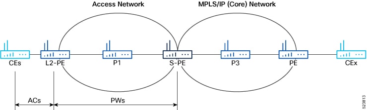
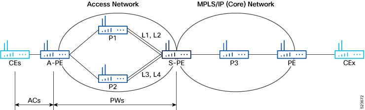
n a PWHE topology, the access network consists of multiple customer edge (CE) devices connected to the access PE (A-PE) via single links. The S-PE is connected to various provider routers using multiple links and line cards, enhancing redundancy and scalability. PWHE integrates L2-PE and S-PE functions and uses BGP with MPLS label distribution (RFC 3107) instead of IGP, simplifying the network and bypassing certain connectivity restrictions.

Summary

The key components involved in the process are:

  • Layer 2 provider edge (L2-PE): Originates pseudowires (PWs) from the access network and connects to the service provider edge.

  • Service provider edge (S-PE): Terminates PWs and emulates the behavior of the access circuit (AC) for PWHE, combining functions previously split between L2-PE and S-PE.

  • Provider routers (P1 and P2): Serve as intermediate nodes between the access provider edge (A-PE) and S-PE, offering connectivity via multiple links and line cards.

  • Generic Interface List (GIL): Groups multiple PWs for streamlined configuration and management, applying changes across all associated PW interfaces.

PWHE changes the traditional access-to-provider-edge network topology by terminating access pseudowires directly on the service provider edge, simplifying Layer 2 VPN deployments. GIL enable efficient management of multiple pseudowire interfaces associated with PWHE.

Workflow

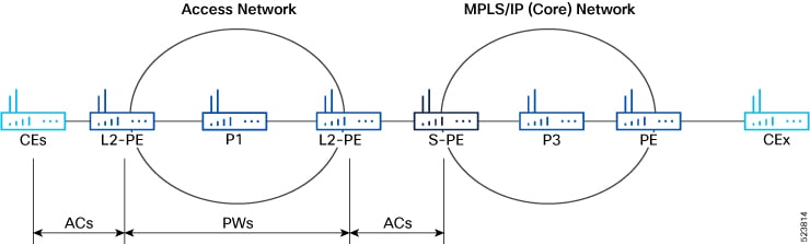
Figure 1. Pseudowire network without PWHE
Figure 2. Pseudowire network with PWHE
Figure 3. PWHE deployment
  1. Access network setup: Multiple provider routers (P1 and P2) are deployed between A-PE and S-PE, each connected via separate links and line cards.
  2. Pseudowire connection establishment: S-PE connects to P1 using links L1 and L2, and to P2 using links L3 and L4; these links attach to distinct line cards for resilience.
  3. Cross-connect configuration: For each CE-A-PE link, a cross-connect (AC-PW) is configured on A-PE, enabling pseudowire traffic between CE and service provider.
  4. PWHE functionality integration: S-PE combines L2-PE and AC functions, terminating pseudowires and using ARP resolution for customer IP addresses, with packets operating in bridged interworking mode (VC type 5).
  5. GIL deployment and management: Multiple PWs are grouped under a generic interface list. Configuration changes to a GIL automatically apply to all associated PW interfaces, streamlining PWHE deployments.

Traffic flow types on PWHE interfaces

There are two types of traffic flow involved in the PWHE interfaces.

  • PWHE decapsulation/disposition flow: This flow occurs when traffic travels from the access side to the core. PWHE ingress features are executed on the PWHE access-facing line card.

  • PWHE encapsulation/imposition flow: This flow occurs when traffic travels from the core to the access side. PWHE egress features are executed on the PWHE access-facing line card.


How PWHE decapsulation works

The packets from access side to core side are decapsulated and the ingress features are executed.

Summary

The key components involved in the process are:

  • Access device: Sends packets into the PWHE router using encapsulated formats.

  • PWHE router: Performs decapsulation by removing headers/labels and reconstructing the packet.

  • Core network: Receives the fully reconstructed packets and forwards them appropriately.

PWHE decapsulation handles the forwarding of packets from the access side to the core network by removing multiple encapsulation layers and reconstructing packets for delivery.

Workflow

These stages describe how PWHE decapsulation work.

  1. The PWHE router receives a packet from the access side.
  2. The PWHE router removes the outer L2 header or VLAN tag.
  3. The PW label is removed from the packet.
  4. The inner L2 header is removed, revealing the payload for later forwarding.
  5. The PWHE router reconstructs the packet with the appropriate transport label, service label, and L2 header needed by the core network.
  6. The reconstructed packet is delivered into the core network.

Result

The process completes when the pseudowire decapsulation and forwarding behavior matches the intended network path, ensuring seamless packet delivery from the access side to the core network.


How PWHE encapsulation works

The packets from core side to access side are encapsulated and the egress features are executed.

Summary

The key components involved in the process are:

  • Core network device: Receives packets and prepares them for encapsulation and forwarding.

  • PWHE encapsulation engine: Adds necessary pseudowire and transport labels, reconstructs the packet, and prepares it for egress.

  • Access network device: Receives the reconstructed packet and handles its final delivery into the access network.

PWHE encapsulation handles the forwarding of packets from the core side to the access side in a network by encapsulating Ethernet frames, reconstructing them with relevant labels, and delivering them to their destination.

Workflow

These stages describe how PWHE encapsulation work.

  1. Encapsulation of L2 header: The core network device receives a packet and the PWHE encapsulation engine encapsulates the inner Layer 2 header.
  2. Packet reconstruction: The encapsulation engine reconstructs the packet by adding a PW label, one or more transport labels, and an outer Layer 2 header.
  3. Packet delivery to access network: The reconstructed packet is forwarded to the access network device, which handles the final delivery.

Result

PWHE encapsulation results in seamless packet forwarding from the core to the access network, ensuring that traffic is properly labeled, encapsulated, and handled according to the specified forwarding path.


Generic interface lists

A Generic interface lists is a PWHE interface grouping construct that

  • groups multiple outgoing interfaces under one logical list

  • applies updates to all associated pseudowire interfaces, and

  • helps scale PWHE deployments that use multiple paths to an access provider edge.

Additional reference information

A generic interface list (GIL) is a list of physical or bundle interfaces used in a PWHE connection. The GIL supports only main interfaces, not subinterfaces. It is bi-directional and restricts both receive and transmit interfaces on access-facing line cards, with no impact on the core-facing side.

A GIL is used to limit the resources allocated for a PWHE interface to the set of interfaces specified in the list.

Only the S-PE is aware of the GIL and expects PWHE packets to arrive only on line cards that contain GIL members. If packets arrive at a line card without GIL members, they are dropped.


Restrictions for pseudowire headend

  • These features are not supported on PWHE:

    • ISIS as IGP for access core

    • PW classVC label 4

    • Segment Routing Traffic Engineering (SR-TE) in the access core for Layer 2 VPN

    • TE tunnel as preferred path in access core for Layer 2 VPN

    • Traffic with Internet Mix (IMIX)

    • The commands load-balancing flow src-dst-ip and flow-label both

    • PWHE load balancing by VC label or by Flow-Aware Transport (FAT)

    • EVPN multihoming mode

    • PWHE MTU

  • The load balancing hashing is performed only by PWHE link numbers.

  • When a packet arrives at PWHE Layer 3 subinterface, the software aggregate count is done on PWHE main interface.

  • Do not use mixed-mode Egress Traffic Management (ETM): avoid combining ETM and non-ETM members within a GIL.

  • Do not use the ECMP path list as a superset of GIL interfaces.

  • If you configure features like QoS and ACL on a GIL, they apply as follows:

    • For PWHE traffic received on GIL, all the features configured on the PWHE interface are applicable.

    • For other traffic received on GIL, all the features configured on the GIL interface are applicable.

  • You can attach ACL in PWHE interface for both ingress and egress, for IPv4 and IPv6.

  • You can attach hybrid-ACL (Level 2) in PWHE interface for only ingress, for IPv4 and IPv6.


Pseudowire headend configuration guidelines

You must meet all these requirements before configuring a PWHE:

  • The generic interface list members must be the superset of the ECMP path list to the Access Provider Edge (A-PE).

  • Only eight generic interface lists are supported per A-PE neighbor address.

  • Eight Layer 3 links per generic interface list are supported.

  • Only PW-Ether interfaces can be configured as PWHE L2 or L3 subinterfaces.

  • Cross-connects that contain PW-Ether main interfaces can be configured as VC-type 5.

  • PW-Ether interfaces and subinterfaces can be configured with both IPv4 and IPv6. The packet-switched network must be capable of routing IPv4 and IPv6 packets to encapsulate and transport these frames over a pseudowire.

  • Pseudowire redundancy, preferred path, local switching or L2TP are not supported for cross-connects configured with PWHE.

  • The TE and LDP applications work on physical interfaces and therefore do not allow PWHE configuration.

  • Address family, CDP, and MPLS configurations are not allowed on PWHE interfaces.

  • For PWHE, eBGP, static routes, OSPF, and ISIS are supported with both IPv4 and IPv6. Routing Information Protocol (RIP) is supported only with IPv4; IPv6 is not supported.

  • You must attach a different generic interface list for PW-Ether interfaces with different remote neighbors. This means creating a separate and dedicated generic interface list for each remote neighbor or peer whose remote neighbors are different routers or devices. The generic interface list may have the same set of outgoing interfaces.


Configure pseudowire headend

Set up pseudowire headend (PWHE) interfaces and cross-connects, including Layer 2 and Layer 3 subinterfaces, on Access Provider Edge (A-PE) and Service Provider Edge (S-PE) routers.

This task uses configuration examples for provider edge roles (A-PE and S-PE) and PWHE interfaces.

Procedure

1.

Configure L2 interface.

Example:

Router(config)# interface hundredGigE 0/1/0/3
Router(config-if)# l2transport
Router(config-if-l2)# root
2.

Configure PWHE cross-connect.

Example:

Router(config)# l2vpn
Router(config-l2vpn)# pw-class pwhe_port_vc5
Router(config-l2vpn-pwc)# encapsulation mpls
Router(config-l2vpn-pwc-mpls)# exit
Router(config-l2vpn-pwc)# exit
Router(config-l2vpn)# xconnect group pw-he
Router(config-l2vpn-xc)# p2p pw-ether1
Router(config-l2vpn-xc-p2p)# interface hundredGigE 0/1/0/3
Router(config-l2vpn-xc-p2p-pw)# neighbor ipv4 10.1.1.1 pw-id 6
Router(config-l2vpn-xc-p2p-pw)# pw-class pwhe_port_vc5
Router(config-l2vpn-xc-p2p-pw)# commit
3.

Create a generic interface list (GIL).

Example:

Router(config)# generic-interface-list txlist
Router(config-gen-if-list)# interface hundredGigE 0/1/0/1
Router(config-gen-if-list)# interface hundredGigE 0/1/0/2
Router(config-gen-if-list)# commit
4.

Configure pw-ether interface and attach GIL

Example:

Router(config)# interface pw-ether1
Router(config-if)# ipv4 address 10.1.1.1/24
Router(config-if)# ipv6 address 2001:DB8::2/64
Router(config-if)# attach generic-interface-list txlist
Router(config-if)# commit
5.

Configure cross-connect to include pw-ether interface.

Example:

Router(config)# l2vpn
Router(config-l2vpn)# pw-class pwhe_port_vc5
Router(config-l2vpn-pwc)# encapsulation mpls
Router(config-l2vpn-pwc-mpls)# transport-mode ethernet
Router(config-l2vpn-pwc-mpls)# exit
Router(config-l2vpn-pwc)# exit
Router(config-l2vpn)# xconnect group pw-he
Router(config-l2vpn-xc)# p2p pw-ether1
Router(config-l2vpn-xc-p2p)# interface pw-ether1
Router(config-l2vpn-xc-p2p)# neighbor ipv4 10.2.2.2 pw-id 6
Router(config-l2vpn-xc-p2p-pw)# pw-class pwhe_port_vc5
Router(config-l2vpn-xc-p2p-pw)# commit

A-PE configuration guidance:

  • Configure the A-PE with PWHE cross-connect to include the L2 interface and PW towards the S-PE. Cross-connect (xconnect) establishes the connection between access provider and service provider edges.

S-PE configuration guidance:

  • On the S-PE, create the generic interface list (GIL), configure the pw-ether interface and attach GIL, and configure cross-connect to include the pw-ether interface (use the transport-mode ethernet command for Ethernet traffic).

6.

Configure L2 subinterface.

A-PE configuration for L2 subinterface:

Example:

Router(config)# interface hundredGigE 0/1/0/3.2 l2transport
Router(config-subif)# encapsulation dot1q 2
Router(config-subif)# rewrite ingress tag pop 1 symmetric

S-PE configuration for L2 subinterface:

Example:

Configure L2 subinterface
Router(config)# interface PW-Ether1.2 l2transport
Router(config-subif)# encapsulation dot1q 1
Router(config-subif)# rewrite ingress tag pop 1 symmetric
7.

Configure cross-connect and assign the L2 subinterface.

Example:

Router(config)# l2vpn
Router(config-l2vpn)# pw-class pwhe_port_vc5
Router(config-l2vpn-pwc)# encapsulation mpls
Router(config-l2vpn-pwc-mpls)# transport-mode vlan
Router(config-l2vpn-pwc-mpls)# exit
Router(config-l2vpn-pwc)# exit
Router(config-l2vpn)# xconnect group pw-he
Router(config-l2vpn-xc)# p2p pw-ether1
Router(config-l2vpn-xc-p2p)# interface pw-ether1.2
Router(config-l2vpn-xc-p2p)# neighbor ipv4 10.2.2.2 pw-id 6
Router(config-l2vpn-xc-p2p-pw)# pw-class pwhe_port_vc5
Router(config-l2vpn-xc-p2p-pw)# commit

There is no need to configure cross-connect for the subinterface, as the main PWHE interface configuration is applied to the subinterface.

8.

Configure Layer 3 (L3) subinterface.

Example:

Router(config)# interface pw-ether 1.1
Router(config-subif)# encapsulation dot1q 1
Router(config-subif)# ipv4 address 10.1.1.1/24
Router(config-subif)# commit

Except for the A-PE, repeat the other configurations as described for the L2 interface.

There is no need to configure cross-connect for the subinterface, as the main PWHE interface configuration is applied to the subinterface.

9.

Use the show generic-interface-list idb name txlist command to verify the details of GIL.

Example:

Router# show generic-interface-list idb name txlist

GIL name: txlist, ifhandle: 0xf000014
  State: Down Immediate
  Members:
    HundredGigE0/1/0/2
    HundredGigE0/1/0/1

Use the show l2vpn xconnect group pw-he xc-name pw-ether1 command to verify that the status of xconnect group with PWHE Up.

Example:

Router# show l2vpn xconnect group pw-he xc-name pw-ether1
Mon Mar 11 21:26:48.281 EDT
Legend: ST = State, UP = Up, DN = Down, AD = Admin Down, UR = Unresolved,
SB = Standby, SR = Standby Ready, (PP) = Partially Programmed,
LU = Local Up, RU = Remote Up, CO = Connected, (SI) = Seamless Inactive

XConnect                  Segment 1       Segment 2
Group     Name        ST  Description ST Description              ST
------------------------ ----------------------------- -----------------------------
pw-he pw-ether1       UP PE1          UP EVPN 1,1,192.0.2.10 UP
----------------------------------------------------------------------------------------

Use the show l2vpn pwhe interface pw-ether 1 detail command to verify that the status of PWHE interface.

Example:

Router# show l2vpn pwhe interface pw-ether 1 detail

Interface: PW-Ether1 Interface State: Up, Admin state: Up
Interface handle 0xf000054
MTU: 1514
BW: 10000 Kbit
Interface MAC addresses: 1859.f57d.0008
Label: 24041
Internal ID: None
L2-overhead: 0
VC-type: 5
CW: Y
Hash: 0xf5f5 [Success]

The pseudowire headend configuration is complete when the router commits your configurations successfully. PWHE interfaces and cross-connects should be operational and verified via the show commands.