|
4. |
Use the show commands to verify the MS-PW configuration.
Example:
Router# show l2vpn xconnect detail
S-PE1:
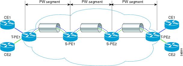
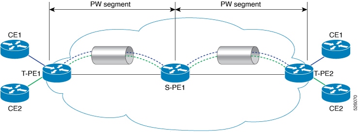
Group MS-PW, XC xc1, State: Up, Type: P2P
PW: neighbor 192.0.2.16, pw-id 1, state: Up (pw-class T-PE1)
PW: neighbor 192.0.2.17, pw-id 1, state: Up (pw-class T-PE2)
Group MS-PW, XC xc2, State: Up, Type: P2P
PW: neighbor 192.0.2.16, pw-id 2, state: Up (pw-class T-PE1)
PW: neighbor 192.0.2.17, pw-id 2, state: Up (pw-class T-PE2)
Note: No local attachment circuits configured (PW-to-PW stitching)
T-PE1:
Group MS-PW, XC xc1, State: Up, Type: P2P
AC: Bundle-Ether111.1, state: Up
PW: neighbor 192.0.2.18, pw-id 1, state: Up (pw-class T-PE1)
Group MS-PW, XC xc2, State: Up, Type: P2P
AC: Bundle-Ether111.2, state: Up
PW: neighbor 192.0.2.18, pw-id 2, state: Up (pw-class T-PE1)
T-PE2:
Group MS-PW, XC xc1, State: Up, Type: P2P
AC: Bundle-Ether333.1, state: Up
PW: neighbor 192.0.2.18, pw-id 1, state: Up (pw-class T-PE2)
Group MS-PW, XC xc2, State: Up, Type: P2P
AC: Bundle-Ether333.2, state: Up
PW: neighbor 192.0.2.18, pw-id 2, state: Up (pw-class T-PE2)
Example:
Router# show mpls ldp neighbor brief
Peer LDP Identifier    Transport Address  State       Uptime
192.0.2.16:0           192.0.2.16          OPERATIONAL  00:34:12
192.0.2.17:0           192.0.2.17          OPERATIONAL  00:34:12
192.0.2.18:0           192.0.2.18          OPERATIONAL  00:34:12
Example:
Router# show mpls forwarding
Local  Outgoing    Prefix             Bytes Label   Outgoing   Next Hop
Label  Label       or ID              Switched      Interface
16001  17001       192.0.2.16:1        100000        Te0/0/0/1  192.0.2.16
16002  17002       192.0.2.17:1        100000        Te0/0/0/2  192.0.2.17
17001  Pop Label   192.0.2.18:1        100000        BE111.1    local
17002  Pop Label   192.0.2.18:2        100000        BE111.2    local
Example:
Router# show mpls l2transport vc detail
S-PE1:
Local interface: none (PW stitching)
VC ID: 1, peer 192.0.2.16, state: UP
  Encapsulation: MPLS, pw-class: T-PE1
VC ID: 1, peer 192.0.2.17, state: UP
  Encapsulation: MPLS, pw-class: T-PE2
VC ID: 2, peer 192.0.2.16, state: UP
  Encapsulation: MPLS, pw-class: T-PE1
VC ID: 2, peer 192.0.2.17, state: UP
  Encapsulation: MPLS, pw-class: T-PE2
T-PE1:
Local interface: Bundle-Ether111.1 up, VC ID: 1
  Peer 192.0.2.18, state: UP, PW class: T-PE1, encapsulation: MPLS, control-word: enabled

Local interface: Bundle-Ether111.2 up, VC ID: 2
  Peer 192.0.2.18, state: UP, PW class: T-PE1, encapsulation: MPLS, control-word: enabled
T-PE2:
Local interface: Bundle-Ether333.1 up, VC ID: 1
  Peer 192.0.2.18, state: UP, PW class: T-PE2, encapsulation: MPLS, control-word: enabled

Local interface: Bundle-Ether333.2 up, VC ID: 2
  Peer 192.0.2.18, state: UP, PW class: T-PE2, encapsulation: MPLS, control-word: enabled
Use the show l2vpn xconnect detail command to check the state of XCs, PWs, and ACs to confirm the end-to-end operational status of the L2VPN service.
Use the show mpls ldp neighbor brief command to verify the state and uptime of LDP neighbors to ensure stable MPLS LDP peering sessions.
Each router shows its direct LDP neighbors only.
Use the show mpls forwarding command to examine label entries to confirm correct MPLS label switching and next-hop forwarding for specific traffic.
Use the show mpls l2transport vc detail command to check the state of each VC and its local interface to verify the operational status of L2 virtual circuits.
|