L2VPN Configuration Guide for Cisco 8000 Series Routers, Cisco IOS XR Releases

PDF

L2VPN Configuration Guide for Cisco 8000 Series Routers, Cisco IOS XR Releases

Integrated routing and bridging

Want to summarize with AI?

Log in

Introduces integrated routing and bridging, covering Bridge-Group Virtual Interface in IRB, prerequisites and planning, packet forwarding behavior, IRB configuration steps, and EVPN IRB architecture with detailed components, operational environments, and benefits.


Integrated routing and bridging (IRB) is a network capability that

  • exchanges traffic between bridging services and a routed interface by using a bridge-group virtual interface (BVI)

  • provides Layer 2 bridging service for hosts in a Layer 2 domain, and

  • provides routing service for hosts that are in different subnets within a Layer 3 VPN.

A bridge-group virtual interface (BVI) is a virtual interface that

  • acts as the Layer 3 gateway for hosts within a bridge domain

  • connects the bridging and routing domains on the device, and

  • is configured with an IP address in the same subnet as the hosts it serves.

Bridge-group virtual interfaces

A Bridge-Group Virtual Interface (BVI) is a virtual interface that

  • acts as a normal routed interface and represents the link between the bridging and routing domains on a router

  • uses a MAC address from the local chassis MAC address pool unless overridden, and

  • uses an IPv4 or IPv6 address in the same subnet as the hosts on the bridged domain.

The BVI identifier is independent of the bridge domain identifier.

BVI interfaces support an identifier range from 1 to 4294967295. Although a BVI does not support bridging itself, it acts as the gateway for the corresponding bridge domain to a routed interface within the router.

BVI interface and line protocol states

The BVI interface is up when the BVI exists and the configured bridge domain has at least one available active bridge port.

  • The bridge domain must be in the up state.

  • The BVI IP address must not conflict with another IP address on an active interface, and

  • The interface remains up if at least one bridge port is up, even when all Ethernet Flow Points (EFPs) are down.

  • If all bridge ports associated with the bridge domain for that BVI are down, the BVI moves to the down state.

If you configure a BVI for a bridge domain, the BVI serves as the gateway for hosts on that domain, distributing IP addresses and routing traffic between the bridged and routed domains.

Best practice for IRB configuration

Follow these best practices before you configure IRB on a BVI:

  • Know the IP addressing and all Layer 3 information you plan to configure on the BVI before you set up IRB.

  • Plan MAC addressing if you intend to override the preferred MAC address for the BVI interface.

    You can replace the preferred MAC address for the BVI interface with the default MAC address allocated from the chassis pool. The MAC address is divided into:

    • 32 bits most significant bits called MAC prefix.

      The router has a limitation of four different MAC prefixes per system. You must not use more than four different MAC prefixes when choosing the MAC address for BVI and other L3 interfaces.

  • 16 bits least significant called MAC host. You can choose any value for the MAC host.

  • Advertise the BVI network by using static or dynamic routing on the BVI interface.


How packet forwarding works in IRB

When IRB is configured on a router, ARP requests are resolved between the hosts and the BVI as part of the bridge domain. This allows for seamless communication between hosts that are either within the same subnet or across routed networks.

Summary

The key components involved in the process are:

  • Host A: Sends traffic from the bridge domain, either to another host on the same subnet or to a host on a routed network.

  • Host B: Receives bridged traffic within the same bridge domain.

  • Host C: Communicates through a routed network connected to the router.

  • BVI: Acts as the logical interface between the bridging domain and the routing domain.

  • Bridging engine: Forwards frames within the bridge domain based on MAC address information.

  • Routing engine: Routes packets between different IP networks.

  • Bridged interfaces: Carry traffic for hosts that belong to the same bridge domain.

  • Routed interface: Carries traffic between the router and external routed networks.

  • ARP: Resolves addresses between hosts and the BVI within the bridge domain.

  • Bridging table: Identifies the correct bridged interface for forwarding frames inside the bridge domain.

IRB enables a router to bridge traffic within a subnet while routing traffic between different subnets, using a logical interface known as the BVI. These flows describe how IRB handles local bridging and routed forwarding.

Workflow

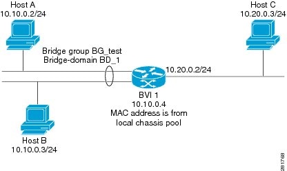
Figure 1. IRB packet flows between hosts

These stages describe the packet-forwarding behavior:

  1. Initial address resolution: ARP resolves address information between the hosts and the BVI within the bridge domain.
  2. Bridged interface packet evaluation: A host on a bridged interface sends a packet. If the destination MAC address matches the BVI MAC address, the packet goes to the BVI. If it does not match, the bridging engine bridges the packet.
  3. Bridging within the same subnet: When Host A sends data to Host B on the 10.10.0.0 network, the router does not route the traffic. The bridging engine forwards the packet between the appropriate bridged segment interfaces because both hosts are on the same subnet.
  4. Sending traffic from the bridge domain to a routed network: When Host A sends data to Host C, Host A sends the packet to the BVI after ARP resolves the BVI address. The packet uses Host A as the source and the BVI as the destination at the MAC level.
  5. Forwarding traffic from the BVI to the routing domain: Because Host C is on another network, the BVI forwards the packet to the routing engine. The router prepares the packet for delivery through the routed interface toward Host C.
  6. Routing traffic to Host C: The routed interface at 10.20.0.2 receives the packet from the BVI side and routes it to Host C at 10.20.0.3.
  7. Receiving traffic from a routed network: When Host C sends data to Host B, the packet enters the router through the routed interface. The packet includes Host C as the source, the ingress interface MAC address as the destination MAC, and Host B as the destination IP.
  8. Routing decision toward the BVI: The routed interface checks the routing table and determines that the packet must go to the BVI at 10.10.0.4.
  9. Forwarding traffic from the routing domain to the bridge domain: The routing engine captures the packet destined for the BVI and forwards it to the corresponding bridge domain.
  10. Final bridging to Host B: The bridging engine checks the bridging table. If Host B’s MAC address appears in the table, the router forwards the packet through the correct bridged interface. If the MAC address does not appear, the router floods the packet on all interfaces in the bridge group.

Result

The IRB process allows the router to bridge local traffic within a subnet and route traffic between different networks through the BVI. This process enables communication between hosts in the bridge domain and hosts on routed networks while preserving the correct forwarding behavior for each traffic type.


Configure IRB

Set up IRB to enable routing and bridging for local and tagged bridge ports.

IRB enables seamless integration of Layer 2 and Layer 3 functionality using a BVI, allowing traffic to be bridged within a domain and routed as needed.

Before you begin

Plan the BVI IP addressing, MAC addressing, and bridge-domain membership before you begin.

Procedure

1.

Configure a BVI and assign IP addresses.

Example:

Router# configure
Router(config)# interface bvi 1
Router(config-if)# ipv4 address 10.10.0.4 255.255.255.0
Router(config-if)# ipv6 address 2001:100:1:1::1/96

Optionally, configure a static MAC address on the BVI interface.

Router(config-if)# mac-address 2001.100.2
Router(config-if)# exit
2.

Configure the Layer 2 AC interface and add it to the bridge domain.

Example:

Router(config)# interface HundredGigE 0/0/0/1 l2transport
Router(config-if-l2)# exit
Router(config)# l2vpn
Router(config-l2vpn)# bridge group 10
Router(config-l2vpn-bg)# bridge-domain 1
Router(config-l2vpn-bg-bd)# interface HundredGigE 0/0/0/1
Router(config-l2vpn-bg-bd-ac)# exit
3.

Associate the BVI with the bridge domain.

Example:

Router(config-l2vpn-bg-bd)# routed interface bvi 1
Router(config-l2vpn-bg-bd-bvi)# commit
4.

Configure IRB for tagged bridge ports using sub-interfaces within a bridge domain.

Example:

Router# configure
Router(config)# interface HundredGigE 0/0/0/2.1 l2transport
Router(config-subif)# encapsulation dot1q 102
Router(config-subif)# rewrite ingress tag pop 1 symmetric
Router(config-subif)# exit
Router(config)# interface bvi 2
Router(config-if)# ipv4 address 56.78.100.1 255.255.255.0
Router(config-if)# ipv6 address 56:78:100::1/64
Router(config-if)# mac-address 2002.100.1
Router(config-if)# exit
Router(config)# l2vpn
Router(config-l2vpn)# bridge group 10
Router(config-l2vpn-bg)# bridge-domain 2
Router(config-l2vpn-bg-bd)# interface HundredGigE 0/0/0/2.1
Router(config-l2vpn-bg-bd-ac)# exit
Router(config-l2vpn-bg-bd)# routed interface bvi 2
Router(config-l2vpn-bg-bd-bvi)# commit
Note

Double VLAN tagged sub-interface is not supported for IRB service.

5.

Use the show interfaces bvi 1 brief command to verify the interface state and packet counters for the BVI.

Example:

Router# show interfaces bvi 1 brief
BVI1 is up, line protocol is up
Interface state transitions: 701
Hardware is Bridge-Group Virtual Interface, address is 2001.0100.0001
Internet address is 10.10.0.4/24
MTU 1514 bytes, BW 10000000 Kbit (Max: 10000000 Kbit)
reliability 255/255, txload 0/255, rxload 1/255
Encapsulation ARPA, loopback not set,
Last link flapped 2d06h
ARP type ARPA, ARP timeout 04:00:00
Last input 00:00:00, output 00:00:13
Last clearing of "show interface" counters 3d18h
30 second input rate 43721000 bits/sec, 49684 packets/sec
30 second output rate 0 bits/sec, 0 packets/sec
15428019162 packets input, 1697081244790 bytes, 0 total input drops
0 drops for unrecognized upper-level protocol
Received 0 broadcast packets, 0 multicast packets
6084259298 packets output, 669870073726 bytes, 0 total output drops
Output 0 broadcast packets, 0 multicast packets

The router bridges local traffic within the bridge domain and routes traffic through the BVI interface.


EVPN IRB

EVPN IRB is a network technology that

  • enables Layer 3 forwarding among hosts across different IP subnets

  • preserves the multihoming capabilities of EVPN, and

  • allows EVPN hosts or subnets to communicate with IP VPNs.

Starting from Release 26.1.1, you can configure EVPN IRB over a Segment Routing over IPv6 (SRv6) core.

Feature History Table

Table 1. Feature History Table

Feature Name

Release Information

Feature Description

EVPN IRB over SRv6 core

Release 26.2.1

Introduced in this release on: Fixed Systems (8010 [ASIC: A100])

This feature is supported on:

  • 8011-4G24Y4H-I

  • 8011-32Y8L2H2FH

  • 8011-12G12X4Y-A/D

EVPN IRB over SRv6 core

Release 26.1.1

Introduced in this release on: Fixed Systems (8200 [ASIC: P100], 8700 [ASIC: P100, K100]); Centralized Systems (8400 [ASIC: K100]); Modular Systems (8800 [LC ASIC: P100])

EVPN IRB enhances network flexibility by enabling seamless Layer 3 connectivity between hosts on different subnets over an SRv6 network. This feature allows Layer 3 forwarding among hosts across IP subnets, maintains EVPN multi-homing capabilities, and facilitates communication between EVPN hosts or subnets and IP VPNs.

Leveraging SRv6 programmable and flexible transport, this solution streamlines the integration and management of modern, diverse network environments.


EVPN IRB components

These components support EVPN IRB traffic management and routing.

  • BGP advertises subnet and host routes to the EVPN core by using route type 5 and route type 2 messages.

  • EVPN manages Ethernet segment configuration, host route advertisement, and failover scenarios.

  • L2RIB handles MAC or IP mobility, route resolution, and best-route computation.

  • BVI manager manages IRB interfaces and advertises BVI subnet and MAC addresses.

  • L2FIB forwards traffic by using MAC and IP information.


EVPN IRB environments

  • Single-homing interface: Customer edge (CE) devices connect directly to a single physical edge (PE) router.

  • Multihoming interface: A CE device connects to multiple PE routers through dual links, a Link Aggregation Group (LAG), or a switch.

  • Anycast gateway or BVI: BVI interfaces use the same IP and MAC addresses on all PE routers so devices can reach the same gateway address regardless of the designated forwarder.

From Release 25.1.1, you can implement EVPN IRB with distributed anycast gateway.


Benefits of EVPN IRB

  • Hosts in the same IP subnet can be provisioned anywhere within the EVPN fabric, supporting flexible VM deployment.

  • Virtual machines in a subnet can move behind different EVPN PE devices without requiring a subnet change.

  • VMs do not need to be directly connected or located in the same physical complex, enabling greater scalability and mobility.

  • EVPN PE devices route traffic efficiently through MPLS encapsulation to maintain connectivity and support seamless VM mobility.


EVPN IRB route types

EVPN IRB uses two main route types to carry Layer 2 and Layer 3 reachability information:

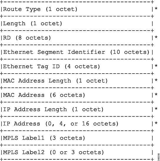
  • Route type 2 (MAC/IP advertisement route): Advertises host IP and MAC addresses to peers within Network Layer Reachability Information (NLRI), reducing unknown unicast flooding.

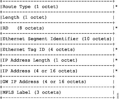
  • Route type 5 (IP prefix route): Advertises IP prefixes in the EVPN domain and integrates Layer 3 routing with the EVPN infrastructure.

Table 2. EVPN IRB route type formats

Route type

NLRI format

Net attributes

Path attributes

Route type 2

[Type][Len][RD][ESI][ETag][MAC Addr Len][MAC Addr][IP Addr Len][IP Addr][MPLS Label1][MPLS Label2]

[Type][RD][ETag][MAC Addr Len][MAC Addr][IP Addr Len][IP Addr]

[ESI], [MPLS Label1], [MPLS Label2]

Route type 5

[Type][Len][RD][ESI][ETag][IP Addr Len][IP Addr][GW IP Addr][Label]

[Type][RD][ETag][IP Addr Len][IP Addr]

[ESI], [GW IP Addr], [Label]

Figure 2. Route type 2 NLRI format
Figure 3. Route type 5 NLRI format

Example policy for route type 2:

route-policy evpn-policy
  if rd in (10.0.0.2:0) [and/or evpn-route-type is 2] [and/or esi in (0000.0000.0000.0000.0000)] [and/or etag is 0] [and/or macaddress in (0013.aabb.ccdd)] [and/or destination in (1.2.3.4/32)] then
    set ..
  endif
end-policy

Example policy for route type 5:

route-policy evpn-policy
  if rd in (30.30.30.30:1) [and/or evpn-route-type is 5] [and/or esi in (0000.0000.0000.0000.0000)] [and/or etag is 0] [and/or destination in (12.2.0.0/16)] [and/or evpn-gateway in (0.0.0.0)] then
    set ..
  endif
end-policy

EVPN IRB with distributed anycast gateways

A distributed anycast gateway is an EVPN IRB feature that

  • provides routing on the first hop

  • enables load balancing and redundancy across PE nodes, and

  • supports communication between EVPN hosts or subnets and IP VPNs.

Feature History Table

Table 3. Feature History Table

Feature name

Release information

Feature description

EVPN IRB with distributed anycast gateway

Release 26.2.1

Introduced in this release on: Fixed Systems (8010 [ASIC: A100]) Modular Systems (8800 [LC ASIC: K100])(select variants only*)

*This feature is supported on:

  • 8011-4G24Y4H-I

  • 8011-32Y8L2H2FH

  • 8011-12G12X4Y-A/D

  • 88-LC1-48Y8F-EM

EVPN IRB with distributed anycast gateway

Release 26.1.1

Introduced in this release on: Centralized Systems (8400 [ASIC: K100]) (select variants only*)

*This feature is supported on Cisco 8404-SYS-D router.

EVPN IRB with distributed anycast gateway

Release 25.4.1

Introduced in this release on: Fixed Systems (8700 [ASIC: K100])(select variants only*)

* This feature is supported on:

  • 8712-MOD-M

  • 8711-48Z-M

EVPN IRB with distributed anycast gateway

Release 25.2.1

Introduced in this release on: Fixed Systems (8200 [ASIC: P100]),8700 [ASIC: P100])(select variants only*); Centralized Systems (8800 [ASIC: P100])(select variants only*)

* This feature is supported on:

  • 8212-48FH-M

  • 8711-32FH-M

  • 88-LC1-36EH

EVPN IRB with distributed anycast gateway

Release 25.1.1

Introduced in this release on: Modular Systems (8800 [LC ASIC: P100])(select variants only*)

EVPN Integrated Routing and Bridging (IRB) facilitates efficient Layer 3 communication across subnets, leveraging PE routers for connectivity over MPLS or IP networks. It supports single and multi-homing, processes packets using VRF table lookups, and enables seamless EVPN to IP VPN communication without route stitching or re-origination.

A distributed anycast gateway enhances routing by sharing IP/MAC addresses for load balancing and redundancy, ensuring optimal performance and reduced latency.

* This feature is supported on:

  • 88-LC1-12TH24FH-E

  • 88-LC1-52Y8H-EM


EVPN IRB capabilities and distributed gateway features

EVPN IRB provides both Layer 2 and Layer 3 VPN overlay services, enabling communication within and across subnets in the same VPN. Its core capabilities include:

EVPN IRB includes these capabilities:

  • Single-homing: Supports connection of a device to a single PE node.

  • Multihoming: Offers all-active, single-active, and port-active multihoming options for redundancy and load balancing.

  • MAC/IP advertisement route: Advertises MAC/IP address bindings within the EVPN network.

  • IP prefix route: Propagates IP prefixes for advanced routing scenarios.

  • MAC aging and MAC freezing: Allows for management of MAC table entries based on activity.

  • Symmetric IRB forwarding: Enables routing of Layer 3 traffic on both source and destination PE nodes for optimal traffic flow and VM mobility.

  • RT-stitching of subnet route (RT2) into VPNv4/VPNv6: Integrates subnet routes into broader VPN infrastructures.

  • Subnet route (RT5) interconnect to VPNv4/VPNv6: Provides interconnection between subnet routes and VPN instances.

  • Distributed anycast L3 gateway: All active PE nodes share the same gateway IP/MAC for redundancy and efficient routing.

EVPN IRB architecture and forwarding model

The EVPN IRB architecture incorporates several important components to enable scalable, resilient data center connectivity:

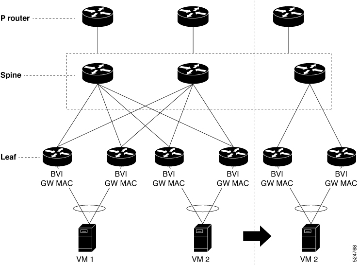
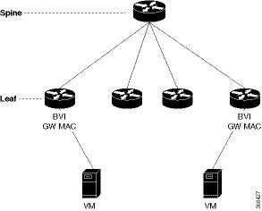
  • Distributed anycast L3 gateway: All PE devices use the same gateway IP and MAC address, ensuring first-hop routing, load balancing, reduced latency, and improved redundancy. Each PE is an active Layer 3 gateway without standby roles.

  • Anycast address in the distributed gateway: For each subnet, all PE nodes use the same gateway IP and MAC address (the anycast pair), supporting redundancy and transparent failover.

  • EVPN PE connectivity: EVPN provider edge (PE) devices connect via a spine-leaf topology and maintain IP reachability to each other’s loopbacks using an MPLS-based underlay fabric.

  • EVPN control plane: An MPLS control plane distributes Layer 2 MAC and Layer 3 IP reachability. This capability enables hosts on the same subnet and Layer 2 domain to communicate across the fabric as if on a single network.

  • Routing service: EVPN supports subnet stretching and seamless inter-subnet Layer 3 VPN services. PEs provide Layer 2 bridging, Layer 3 VPN services, and inter-subnet routing within the VPN.

  • Symmetric IRB forwarding: Layer 3 traffic between hosts is routed both at the source and destination PE, supporting a single anycast gateway address and maintaining VM mobility. The forwarding model ensures optimal traffic flow.


How EVPN IRB distributed anycast gateway works

This process is essential in data centers where workloads frequently migrate, ensuring uninterrupted service and simplified network management during VM mobility.

Summary

The key components involved in the process are:

  • EVPN PE: Acts as the gateway, handles Layer 2 and Layer 3 forwarding, and supports the anycast gateway functionality across devices.

  • Virtual machines (VMs): Endpoints that retain connectivity and their assigned IP/MAC addresses even when they move to different hosts or switches.

  • MPLS tunnels (fabric): Carry traffic between PEs, enabling layer-2 extension and distributed gateway services.

The EVPN IRB distributed anycast gateway process enables virtual machines to maintain seamless connectivity and consistent addressing as they move within the data center, by leveraging distributed gateway configuration and optimized traffic forwarding.

Workflow

These stages describe the EVPN IRB distributed anycast gateway process:

  1. Gateway configuration and distribution: Each EVPN PE in the fabric is configured with the same anycast gateway MAC and IP addresses for the relevant subnet. This ensures every PE acts as a gateway for local VMs.
  2. VM connectivity and mobility: When a VM connects to a switch, it uses the local PE's anycast gateway for default routing (Layer 3), regardless of location. If the VM migrates to another host or PE, it continues to use the same MAC/IP gateway address, eliminating the need to update its network configuration.
  3. Traffic forwarding across the Ffabric: Traffic between VMs in the same subnet but on different PEs is carried via MPLS tunnels. The distributed anycast gateway ensures efficient east-west traffic flow by routing packets as close to the destination as possible, reducing tromboning.
  4. Gratuitous ARP/ND and MAC learning: When a VM migrates, the local PE immediately broadcasts a gratuitous ARP or Neighbor Discovery message so that the new location is learned by other devices, allowing swift redirection of traffic and avoiding traffic loss.

Key characteristics of the MAC and IP unicast control plane for distributed anycast gateway

The MAC and IP unicast control plane in a distributed anycast gateway supports several routing models and behaviors in an EVPN fabric, including prefix routing, host routing, ARP and MAC synchronization, and route re-origination.

Prefix routing (no subnet stretch)

  • Establishes IP reachability using subnet prefix routes advertised via EVPN Route Type 5 with VPN labels and VRF route targets.

  • Synchronizes host ARP and MAC entries across multi-homing EVPN PEs using MAC+IP Route Type 2 with a shared Ethernet Segment Identifier (ESI), supporting BVI all-active multihoming and load balancing.

Host routing (stretched subnet)

  • When a host is discovered via ARP, it advertises MAC and IP Route Type 2 with MAC VRF route targets, IP VRF route targets, and VPN labels for both MAC-VRF and IP-VRF.

  • Associates VRF route targets and Layer 3 VPN labels with Route Type 2 to enable PE-to-PE IP routing consistent with traditional L3VPN behavior.

  • Allows remote EVPN PEs to install IP/32 host entries directly in the Layer 3 VRF table using the advertising EVPN PE next hop with Layer 3 VPN label encapsulation.

  • Provides a scale advantage by enabling multiple IP hosts in a stretched subnet to share forwarding rewrites or load-balancing resources.

ARP and MAC sync

  • Hosts connecting through a LAG to multiple EVPN PEs are learned locally in the data plane.

  • The router synchronizes these ARP and MAC entries across multihoming EVPN PEs using MAC and IP Route Type 2 with a shared ESI.

  • When a router receives a MAC and IP Route Type 2 with a local ESI, it installs a synchronized MAC entry pointing to the local AC port and a synchronized ARP entry on the local BVI interface.

MAC and IP route re-origination

  • Routers may re-originate MAC and IP Route Type 2 received with local ESI for MAC and ARP synchronization if the host is not locally learned.

  • Re-origination is required to establish overlay IP ECMP paths on remote EVPN PEs and to minimize traffic impact during local AC link failures, which can trigger MAC and IP route withdrawal.

Table 4. Key characteristics
Area Reference information
IP reachability The fabric uses Route Type 5 for subnet prefix routing and Route Type 2 for host-specific routing and synchronization.
Multihoming support The design uses a shared ESI to synchronize MAC and ARP information across multihoming EVPN PEs.
Stretched subnet behavior Remote PEs install IP/32 routes directly in the Layer 3 VRF by using the advertising PE next hop and Layer 3 VPN label.
Scale benefit The design reduces per-host forwarding state by allowing shared forwarding rewrites or load-balance resources.
Resiliency Route re-origination helps maintain overlay ECMP and reduces traffic disruption during local access link failures.

EVPN single-homing access gateway

A single-homing method in EVPN is an access-gateway architecture that

  • connects each customer edge (CE) device to only one provider edge (PE) device

  • preserves EVPN host and subnet reachability, and

  • enables PE devices to learn and advertise MAC and IP addresses for optimal connectivity.

All the PE nodes add host routes to the IP-VRF table, and the EVPN PE nodes add MAC routes to the MAC-VRF table. The PE device attaches to the Ethernet Segment through bundle interfaces or physical interfaces, using a Null Ethernet Segment Identifier (ESI) for single-homing.

Feature History Table

Table 5. Feature History Table

Feature Name

Release Information

Feature Description

EVPN single-homing access EVPN gateway over SRv6 core

Release 26.1.1

Introduced in this release on: Fixed Systems (8200 [ASIC: P100], 8700 [ASIC: P100, K100]); Centralized Systems (8400 [ASIC: K100]); Modular Systems (8800 [LC ASIC: P100])

You can deploy an EVPN single-homing access EVPN gateway to provide Layer 2 and Layer 3 VPN services using EVPN technology over an SRv6 core. In this architecture, each customer edge (CE) device is connected to only one provider edge (PE) device, enabling a single-homed configuration that simplifies connectivity between CE devices and the service provider programmable, flexible SRv6 network.


How EVPN single-homing access gateway works

EVPN single-homing is used when a customer edge device connects to only one provider edge device, simplifying deployment and eliminating redundancy.

Summary

The key components involved in the process are:

  • Customer Edge (CE) device: Connects to the network through the access gateway and interfaces with customer resources.

  • Provider Edge (PE) device: Serves as the single point of connection for the CE device and attaches to the Ethernet segment.

  • Ethernet Segment Identifier (ESI): Identifies the Ethernet segment. For single-homing, a null ESI is used.

The EVPN single-homing access gateway provides network connectivity for a single-homed customer by linking a CE device to the provider’s backbone through a single PE device and an Ethernet segment.

Workflow

Figure 4. How EVPN single-homing access gateway works

These are the stages of EVPN single-homing access gateway:

  1. Device connection: The CE device connects to the PE device using a physical or bundle interface.
  2. Null ESI configuration: The PE device is configured with a null ESI to specify that only a single PE serves a given Ethernet segment.
  3. EVPN route advertisement: The PE device advertises the CE connection into the EVPN network using BGP.
  4. Traffic forwarding: The PE forwards traffic between the CE device and the core network, ensuring only one active path and no multi-homing redundancy.

EVPN all-active multihoming access gateway

An EVPN all-active multihoming access gateway is a network access-gateway model that

  • allows a customer edge (CE) device to connect to more than one provider edge (PE) device for redundancy

  • prevents disruptions to network connectivity by enabling multihoming through various Ethernet links, and

  • uses the Multi-chassis Link Aggregation Group (MC-LAG) bundle as an Ethernet segment to aggregate these connections.

An Ethernet segment refers to the group of Ethernet links that connect a CE device to multiple PE devices in an all-active multihoming deployment. The MC-LAG bundle allows all connected links to participate actively, providing efficient load balancing and rapid failover should any single link or device fail.

EVPN IRB behavior in all-active multihoming without subnet stretch or host-routing across the fabric

EVPN IRB with all-active multihoming without subnet stretch or host-routing across the fabric provides a distributed anycast gateway for subnets that remain local to a set of multi-homing EVPN PEs.

For these local subnets, the solution advertises subnet routes by using EVPN Route Type 5 to remote leaf nodes that host the VRF. It does not require advertising /32 host routes within the subnet across the fabric. However, host MAC and ARP entries must remain synchronized across the EVPN PEs to which the servers are multi-homed.

Characteristics

  • Uses all-active Ethernet LAG on the access side.

  • Uses Layer 3 ECMP across the fabric for dual-homed hosts based on subnet routes.

  • Does not stretch the Layer 2 subnet from remote PEs to the local EVPN IRB multi-homing PE.

  • Supports Layer 2 stretch only within the redundancy group of leaf nodes that contain orphan ports.

Route and state handling across multihoming EVPN PEs

  • Local ARP cache entries and MAC addresses for dual-homed hosts are synchronized through EVPN MAC+IP host route advertisements.

  • These routes are imported as local routes based on the local ESI match, which supports optimal forwarding to the access gateway.

  • Orphan MAC addresses and host IP addresses are installed as remote addresses over the fabric.

  • ES and EAD routes are exchanged for designated forwarder (DF) election and split-horizon labeling.

Route handling across remote EVPN PEs

  • Dual-homed MAC+IP EVPN Route Type 2 routes are exchanged with the ESI, EVI label, and Layer 2 route type.

  • If there is no subnet stretch or host-routing, these Route Type 2 routes are not imported across the fabric.

  • Subnet IP EVPN Route Type 5 routes are exchanged with the VRF label and Layer 3 route type.

  • Layer 3 route types are imported only for VRFs that are present locally.

  • Layer 2 route types for locally present bridge domains (BDs) are imported.

  • If a BD is not stretched, the Layer 2 route type is imported only from the leaf in the same redundancy group.

Summary

This model uses prefix routing for inter-subnet traffic from remote PEs to the EVPN IRB multi-homing PE. It keeps host synchronization where needed for dual-homed access while avoiding subnet stretch and host-route distribution across the broader fabric.

To configure the BVI for EVPN IRB with all-active multihoming without subnet stretch or host-routing across the fabric, see the Configure IRB section.


EVPN IRB behavior in all-active multihoming with subnet stretch or host-routing across the fabric

EVPN IRB with all-active multihoming with subnet stretch or host-routing across the fabric distributes both /32 host routes and MAC routes in the EVPN overlay control plane. This model enables both Layer 2 and Layer 3 traffic forwarding to endpoints that belong to a stretched subnet across remote EVPN PEs.

Characteristics

  • Uses Layer 2 or Layer 3 ECMP across the fabric for dual-homed hosts based on Route Type 1 and Route Type 2.

  • Uses Layer 3 unipath across the fabric for single-homed hosts based on Route Type 2.

  • Supports Layer 2 subnet stretch across the fabric.

  • Supports Layer 2 stretch within the redundancy group of leaf nodes that contain orphan ports.

Traffic and route distribution

  • Distributes /32 host routes across the EVPN overlay control plane.

  • Distributes MAC routes across the EVPN overlay control plane.

  • Enables Layer 2 connectivity to endpoints in stretched subnets.

  • Enables Layer 3 connectivity to endpoints in stretched subnets.

Scope and limitation

  • The subnet stretch feature with EVPN IRB is available only within VRF instances.

  • The subnet stretch feature does not apply to the global VRF.

To configure the BVI for EVPN IRB with all-active multi-homing with subnet stretch or host-routing across the fabric, see the Configure EVPN IRB with distributed anycast gateway section.


EVPN IRB port-active multihoming

EVPN IRB port-active multihoming mode is a network model that

  • sends traffic to a specific interface, avoiding per-flow load balancing across multiple PE routers

  • can be enabled only on bundle interfaces, and

  • supports both Layer 2 and Layer 3 port-active functionality on the same bundle while using designated forwarder (DF) election to determine the active and standby PE.

You can use either the modulo algorithm or the Highest Random Weight (HRW) algorithm for per-port DF election. By default, the modulo algorithm is used. If the interface runs LACP, the standby side sets LACP to Out-of-Service instead of bringing the interface down.


EVPN IRB port-active multihoming behavior and benefits

EVPN IRB port-active multihoming improves convergence during a link failure by allowing only one physical port to remain active at a time. This model simplifies protocol operation because traffic uses a single active port while the other port remains in standby. This functionality is available only on bundle interfaces.

Key benefits

  • Provides faster convergence during link failure.

  • Simplifies protocol operation because only one physical port is active at a given time.

  • Acts as an alternative to multi-chassis link aggregation group (MC-LAG) with ICCP.

  • Supports deployments where certain QoS features must operate correctly.

Comparison with ICCP-based MC-LAG

  • EVPN port-active simplifies the protocol model compared to Inter-Chassis Communication Protocol (ICCP).

  • I

    CCP runs on top of Label Distribution Protocol (LDP).

  • EVPN port-active can replace MC-LAG with ICCP in suitable deployments.

Port activity model

  • One PE operates in active mode at the port level.

  • Another PE operates in standby mode at the port level.

  • Only the PE in active mode sends and receives traffic.

  • The PE in standby mode does not forward traffic while it remains in standby.

Designated forwarder election

  • The PEs use the Designated Forwarder (DF) election mechanism to determine active and standby roles.

  • The DF election selects which PE must operate in active mode and which PE must operate in standby mode.

  • The per-port DF election supports the modulo algorithm.

  • The per-port DF election also supports the Highest Random Weight (HRW) algorithm.

  • The modulo algorithm is the default selection.


How EVPN IRB port-active multihoming works

This process supports EVPN IRB multihoming deployments where the customer edge device connects redundantly to two provider edge devices. Only one interface forwards traffic at a time, with fast switch-over between standby and active modes to maintain seamless service.

Summary

The key components involved in the process are:

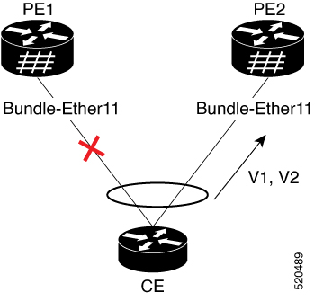
  • Customer edge device (CE): Connects to both provider edge devices through a multihomed topology and uses single link aggregation.

  • Provider edge device 1 (PE1): Operates in standby mode and keeps its services in standby when it is not the active forwarding device.

  • Provider edge device 2 (PE2): Operates in active mode and carries traffic from the customer edge device.

  • Active interface: Remains in the forwarding state and handles traffic and service operation.

  • Standby interface: Remains in the standby state and does not forward traffic unless an active-to-standby transition occurs.

  • LACP: Sets the standby interface state to Out-of-Service (OOS) instead of bringing the interface down, which improves convergence during transition.

  • L2 and L3 subinterfaces: Participate in EVPN IRB and allow both Layer 2 and Layer 3 port-active functionality to coexist on the same bundle.

EVPN IRB port-active multihoming enables a customer edge device to connect redundantly to two provider edge devices, ensuring only one interface actively forwards traffic at a time. This approach supports rapid convergence and maintains efficient traffic handling and service operation.

Workflow

These stages describe how EVPN IRB port-active multihoming works:

  1. Topology establishment: The customer edge device connects to PE1 and PE2 in a multihomed topology and uses single link aggregation
  2. Role assignment: The system places one interface in the forwarding state and places the other interface in the standby state.
  3. Active forwarding: PE2 operates in active mode and carries traffic from the customer edge device.
  4. Standby service state: PE1 operates in standby mode, and all services on its interface remain in standby.
  5. LACP standby handling: If the interface runs LACP, the standby device sets the LACP state to Out-of-Service instead of setting the interface state down.
  6. Convergence improvement: The Out-of-Service state helps the system achieve better convergence when the standby interface transitions to active mode.
  7. Port-active reconfiguration: If an operator removes the port-active configuration from both PE1 and PE2 and then adds it back on both devices, the system selects PE2 as the active interface again.
  8. Mixed service support: The bundle supports both Layer 2 and Layer 3 port-active functionality at the same time.
  9. EVPN IRB participation: The same bundle includes a mix of L3 subinterfaces and L2 subinterfaces that participate in EVPN IRB.

EVPN single-active multihoming for anycast gateway IRB

A single-active multihoming for anycast gateway IRB is an EVPN forwarding model that

  • uses one Provider Edge (PE) device to forward traffic to and from an Ethernet Segment within each EVPN service instance

  • enables local PE nodes connected to the Ethernet segment to load-balance traffic based on the Ethernet Virtual Instance (EVI), and

  • performs designated forwarder (DF) election between PEs to ensure that only the DF forwards traffic while the non-DF blocks traffic in both directions.

Feature History Table

Table 6. Feature History Table

Feature Name

Release Information

Feature Description

EVPN single-active multihoming for anycast gateway over SRv6 core

Release 26.1.1

Introduced in this release on: Fixed Systems (8200 [ASIC: P100], 8700 [ASIC: P100, K100]); Centralized Systems (8400 [ASIC: K100]); Modular Systems (8800 [LC ASIC: P100])

You enable EVPN single-active multihoming for anycast gateway IRB over an SRv6 core to provide single-active redundancy, where only one PE forwards traffic for an Ethernet Segment within each EVPN service instance. This feature supports intersubnet scenarios and balances traffic based on the EVI, leveraging a programmable, flexible SRv6 network.


How EVPN single-active multihoming for anycast gateway IRB works

This process supports EVPN multihoming in single-active mode. This mode ensures that only one peering PE forwards traffic for a shared EVI at a time, while the other PE remains blocked. This behavior prevents duplicate forwarding and provides failover when the active path fails.

Summary

The key components involved in the process are:

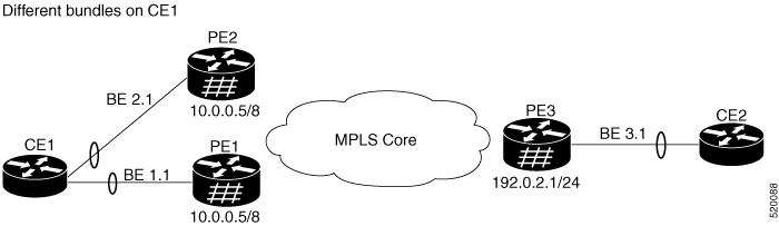
  • CE1 and CE2: A multihomed customer edge device that connects to both PE1 and PE2 through bundle Ethernet interfaces in the same switching domain.

    CE2: A customer edge device that receives traffic from PE3.

  • PE1: A peering provider edge device that participates in host routing, uses the anycast gateway IP address, advertises Type 4 routes, and can become the designated forwarder.

  • PE2: A peering provider edge device that mirrors the PE1 configuration, participates in designated forwarder election, and remains in standby or blocked state when it is the non-DF.

  • PE3: A remote provider edge device that connects to CE2 through an Ethernet interface bundle and exchanges reachability information with PE1 and PE2 through the MPLS core.

  • Bundle Ethernet interfaces BE 1.1 and BE 2.1: The multihomed access interfaces on CE1 that must belong to the same switching domain.

  • MPLS core: The transport network that connects PE1 and PE2 to PE3.

  • Anycast gateway IP address: The shared gateway address configured on both peering PEs to provide consistent gateway behavior.

  • Type 4 EVPN routes: The routes PE1 and PE2 advertise to signal multihoming information and support designated forwarder election.

  • Designated forwarder election: The mechanism that selects the active forwarding PE for the shared Ethernet VPN instance in single-active mode.

This process describes how EVPN single-active multihoming forwards traffic between a multihomed customer edge device and a remote customer edge device by electing a designated forwarder and blocking the standby path.

Workflow

These stages describe how EVPN single-active multihoming for anycast gateway IRB works:

  1. Configure the multihomed access: CE1 connects to PE1 and PE2 through bundle Ethernet interfaces BE 1.1 and BE 2.1, and the ingress interface belongs to the same switching domain on CE1.
  2. Enable EVPN gateway and reachability functions: PE1 and PE2 enable host routing, configure the same anycast gateway IP address, connect to PE3 through the MPLS core, and maintain reachability with PE3 subnets. CE2 connects to PE3 through an Ethernet interface bundle.
  3. Advertise multihoming information: PE1 and PE2 advertise EVPN Type 4 routes for the shared EVI.
  4. Elect the designated forwarder: PE1 and PE2 perform designated forwarder election. In single-active mode, one PE becomes the DF and the other PE becomes the non-DF.
  5. Block the standby path: The non-DF blocks traffic in both directions, so only the DF forwards traffic for the shared EVI.
  6. Process the ARP request from CE1: CE1 sends an ARP broadcast request to both PE1 and PE2. If PE1 is the DF, PE1 replies to the ARP request and PE2 drops the traffic from CE1.
  7. Forward unicast traffic through the active PE: After ARP resolution completes, CE1 sends unicast traffic only through the DF. The non-DF remains in standby or blocked state and does not forward traffic.
  8. Exchange remote MAC and data traffic: The active PE advertises the MAC to PE3, and PE3 always sends and receives traffic through that active PE. PE3 forwards the traffic to CE2 over the Ethernet interface bundle.
  9. Fail over to the standby PE when the active bundle fails: If BE1 fails, PE2 becomes the designated forwarder and traffic starts to flow through PE2.

Configure EVPN IRB with distributed anycast gateway

Set up distributed anycast gateway IRB using EVPN, enabling seamless bridging and routing between Layer 2 and Layer 3 domains with enhanced redundancy.

Use this task when you need to implement distributed anycast gateway functionality for IRB in your EVPN deployment, providing efficient and redundant Layer 3 gateway services across your network.

Procedure

1.

Configure EVPN distributed anycast IRB in the bridge domain.

Example:

Router(config)# l2vpn
Router(config-l2vpn)# bridge group 10
Router(config-l2vpn-bg)# bridge-domain 2
Router(config-l2vpn-bg-bd)# routed interface BVI10
Router(config-l2vpn-bg-bd-bvi)# split-horizon group core
Router(config-l2vpn-bg-bd-bvi)# exit
Router(config-l2vpn-bg-bd)# evi 100
Router(config-l2vpn-bg-bd)# exit
Router(config-l2vpn-bg)# exit
Router(config-l2vpn)# commit
2.

Configure the BVI interface for the EVPN routing model that you need.

Example:

Router# configure
Router(config)# interface BVI10
Router(config-if)# host-routing
Router(config-if)# vrf 30
Router(config-if)# ipv4 address 10.0.0.5 255.0.0.0
Router(config-if)# local-proxy-arp
Router(config-if)# mac-address 1.1.1
Router(config-if)# commit

To configure the BVI without subnet stretch, omit host-routing and local-proxy-arp.

Router# configure
Router(config)# interface BVI10
Router(config-if)# vrf 30
Router(config-if)# ipv4 address 10.0.0.5 255.0.0.0
Router(config-if)# mac-address 1.1.1
Router(config-if)# commit
3.

Configure EVPN BGP signaling and add the attachment circuit to the bridge domain.

Example:

Router# configure
Router(config)# router bgp 200
Router(config-bgp)# bgp router-id 10.10.10.1
Router(config-bgp)# address-family l2vpn evpn
Router(config-bgp-af)# neighbor 10.10.10.10
Router(config-bgp-nbr)# remote-as 200
Router(config-bgp-nbr)# update-source Loopback0
Router(config-bgp-nbr)# address-family l2vpn evpn
Router(config-bgp-nbr-af)# exit
Router(config-bgp)# exit
Router(config-evpn)# evi 100
Router(config-evpn-evi)# advertise-mac
Router(config-evpn-evi)# exit
Router(config-evpn)# exit
Router(config)# l2vpn
Router(config-l2vpn)# bridge group 10
Router(config-l2vpn-bg)# bridge-domain 2
Router(config-l2vpn-bg-bd)# interface FourHundredGigE0/0/0/0.2
Router(config-l2vpn-bg-bd)# exit
Router(config-l2vpn-bg)# exit
Router(config-l2vpn)# exit
Router(config)# exit
4.

Configure the access pseudowire in the bridge domain.

Example:

Router# configure
Router(config)# l2vpn
Router(config-l2vpn)# bridge group 10
Router(config-l2vpn-bg)# bridge-domain 2
Router(config-l2vpn-bg-bd)# neighbor 192.0.2.1 pw-id 100
Router(config-l2vpn-bg-bd)# commit

The bridge domain is now enabled for distributed anycast gateway IRB with EVPN signaling and access connectivity. The configuration provides high-availability and seamless integrated routing and bridging across the EVPN fabric.


EVPN IRB software MAC learning

EVPN IRB software MAC learning is a network capability that

  • learns the MAC addresses of devices available in a VLAN

  • distributes MAC addresses learned on one device to other devices in the VLAN, and

  • uses BGP to learn MAC addresses from remote devices.

  • MAC address: A hardware address that identifies a device on a network.

  • VLAN: A logical network segment that groups devices into the same broadcast domain.

  • BGP: A routing protocol that can distribute reachability information, including MAC address information in EVPN environments.

MAC learning identifies which MAC addresses belong to devices on a VLAN. In EVPN IRB software MAC learning, this information does not stay only on the local device. Instead, the learned MAC addresses propagate to other connected devices so that the network maintains consistent forwarding information across the VLAN.

  • A switch learns a host MAC address on a local VLAN and shares that information with other devices in the same EVPN network.

  • A remote device advertises MAC address information through BGP, and another device installs that information for forwarding decisions.


How software MAC learning works in EVPN IRB

MAC learning is the method of learning the MAC addresses of all devices available in a VLAN.

The MAC addresses learned on one device must also be learned or distributed to the other devices in the VLAN. Software MAC learning enables the distribution of the MAC addresses learned on one device to the other devices connected to the network, and the remote devices learn those MAC addresses through BGP.

Summary

The key components involved in the process are:

  • Ingress device: Learns the source MAC address as traffic enters its port in the bridge domain.

  • BGP protocol: Converts learned MAC addresses into type-2 BGP routes for distribution across the EVPN.

  • Remote PE devices: Receive and update MAC addresses as static remote entries to maintain synchronized address tables.

Software MAC learning enables the distribution of MAC addresses learned on one device to other devices within the EVPN IRB network, ensuring consistent MAC address knowledge across network nodes.

Workflow

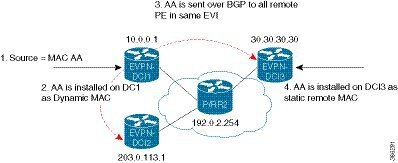
Figure 5. Software MAC learning

These stages describe the software MAC learning process.

  1. Traffic enters one port in the bridge domain.
  2. The ingress device learns the source MAC address and stores it as a dynamic MAC entry.
  3. The MAC address is converted into a type-2 BGP route and sent over BGP to all remote PEs in the same EVI.
  4. Each remote device updates the MAC address as a static remote MAC entry.

Result

At the end of the process, all EVPN devices in the IRB network maintain synchronized MAC address tables, enabling seamless communication and optimized forwarding across the VLAN.

MAC freezing in EVPN IRB

MAC freeze mechanism is a duplicate IP address detection feature that

  • identifies hosts assigned duplicate IP addresses, either unintentionally or by malicious intent

  • automatically blocks all MAC-IP routes associated with the duplicate IP address, and

  • temporarily or permanently freezes routes when duplicate-detection thresholds are exceeded.

The router manages mobility of EVPN hosts by tracking MAC and IP addresses as they move across hosts. When two hosts are assigned the same IP address, IOS XR continually learns and re-learns MAC-IP routes from both hosts. Each MAC-IP route learning event is counted as a "move" because the newly learned route replaces the previous route from the other host.

These parameters control duplicate detection:

  • move-interval : The period within which a MAC or IP address has to move certain number of times between different hosts to be considered as duplicate and frozen temporarily. This number is specified in the move-count parameter.

  • move-count : The number of times a MAC or IP address has to move within the interval specified for the move-interval parameter between different hosts to be considered a duplicate.

  • freeze-time : The length of time a MAC or IP address is locked after it has been detected as a duplicate. After this period, the IP address is unlocked and it is allowed to learn again.

  • retry-count : The number of times a MAC or IP address is unlocked after it has been detected as a duplicate before it is frozen permanently.

When an IP address moves the specified number of times (move-count ) within a specified interval (move-interval ), the IP address is flagged as duplicate, and associated MAC-IP routes are frozen for the duration defined by freeze-time . After freeze-time elapses, MAC-IP routes are unfrozen, move-count resets to zero, local MAC-IP routes trigger ARP probe and flush, and remote MAC-IP routes re-enter probe mode to restart duplicate detection.

Manual unfreeze commands

The router maintains the number of times a particular IP address has been frozen and unfrozen. If an IP address is marked as duplicate again after it has been unfrozen retry-count times, it is frozen permanently until you manually unfreeze it.

The router records the number of times a particular IP address has been frozen and unfrozen. If an IP address is marked as duplicate more times than allowed by retry-count , it is frozen permanently until manually unfrozen. To unfreeze, use one of these commands:

  • clear l2route evpn mac {mac-address} | all [evi evi] frozen-flag

  • clear l2route evpn ipv4 {ipv4-address} | all [evi evi] frozen-flag

  • clear l2route evpn ipv6 {ipv6-address} | all [evi evi] frozen-flag

A syslog notifies the user when an IP address is frozen. While an IP address is frozen, any new MAC-IP routes or updates to existing MAC-IP routes with that frozen IP address are ignored.


Configure MAC freezing

Configure MAC freezing parameters to detect and prevent duplicate IP addresses on your network, reducing operational issues and improving security.

MAC freezing helps identify devices with duplicate IP addresses and temporarily freezes their MAC to prevent conflicts and maintain proper routing.

Procedure

1.

Configure duplicate detection for IPv4 and IPv6 addresses.

Example:

Router# configure
Router(config)# evpn
Router(config-evpn)# host ipv4-address duplicate-detection
Router(config-evpn-host-ipv4-addr)# move-count 2
Router(config-evpn-host-ipv4-addr)# freeze-time 10
Router(config-evpn-host-ipv4-addr)# retry-count 2
Router(config-evpn-host-ipv4-addr)# commit
Router(config-evpn-host-ipv4-addr)# end

Router# configure
Router(config)# evpn
Router(config-evpn)# host ipv6-address duplicate-detection
Router(config-evpn-host-ipv6-addr)# move-count 2
Router(config-evpn-host-ipv6-addr)# freeze-time 10
Router(config-evpn-host-ipv6-addr)# retry-count 2
Router(config-evpn-host-ipv6-addr)# commit
2.

Check the running configuration.

Example:

Router# show running-config
evpn
 host ipv4-address duplicate-detection
  move-count 2
  freeze-time 10
  retry-count 2
 !
!
evpn
 host ipv6-address duplicate-detection
  move-count 2
  freeze-time 10
  retry-count 2
 !
3.

Use the show l2route evpn mac-ip all detail to verify duplicate IP address detection and recovery parameters.

Example:

Router# show l2route evpn mac-ip all detail

Flags:  (Stt)=Static; (L)=Local; (R)=Remote; (F)=Flood;
        (N)=No Redistribution; (Rtr)=RP/0/RSP0/CPU0:router MAC; (B)=Best Route;
        (S)=Peer Sync; (Spl)=Split; (Rcv)=Recd;
        (D)=Duplicate MAC; (Z)=Frozen MAC;
Topo ID    Mac Address     IP Address  Prod   Next Hop(s)        Seq No  Flags         Opaque Data Type    Opaque Data Len   Opaque Data Value
-------    -----------     ----------  ----   ----------         ------  -----         ----------------    ---------------   -----------------
33         0022.6730.0001  10.130.0.2  L2VPN  Bundle-Ether6.1300  0      SB 0 12      0x06000000