L2VPN Configuration Guide for Cisco 8000 Series Routers, Cisco IOS XR Releases

PDF

L2VPN Configuration Guide for Cisco 8000 Series Routers, Cisco IOS XR Releases

Pseudowire over MPLS

Want to summarize with AI?

Log in

Describes pseudowire over MPLS operation, covering route processor failover requirements, traffic transport topologies, static cross-connect circuit functionality and requirements, as well as procedures for configuring static and dynamic point-to-point cross-connects.


A pseudowire over MPLS is a tunneling mechanism, also known as Ethernet-over-MPLS, that

  • connects two provider edge devices and links the attachment circuits at each provider edge device over the MPLS network

  • provides a common intermediate format to transport IPv4, IPv6, MPLS, and Ethernet services over a packet switched network, and

  • encapsulates Ethernet protocol data units with MPLS labels to forward them through an MPLS-enabled Layer 3 core network.

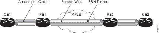
A pseudowire (PW) is a point-to-point connection between two provider edge (PE) devices that connects two attachment circuits (ACs).

A packet switched network (PSN) is a network that forwards packets, such as IPv4, IPv6, MPLS, and Ethernet.

Ethernet protocol data units (PDUs) are encapsulated by pseudowire over MPLS with MPLS labels before they are forwarded across the MPLS network.

Feature history

Table 1. Feature History Table

Feature Name

Release Information

Feature Description

Pseudowire over MPLS

Release 26.2.1

Introduced in this release on: Modular Systems (8800 [LC ASIC: K100])(select variants only*);

*This feature is supported on Cisco 88-LC1-48Y8H-EM line cards.

Pseudowire over MPLS

Release 25.4.1

Introduced in this release on: Fixed Systems (8010 [ASIC: A100])(select variants only*)

*This feature is supported on:

  • 8011-32Y8L2H2FH

  • 8011-12G12X4Y-A/D

Pseudowire over MPLS

Release 25.1.1

Introduced in this release on: Fixed Systems (8700 [ASIC: K100], 8010 [ASIC: A100])(select variants only*)

*This feature is supported on:

  • 8011-4G24Y4H-I

  • 8712-MOD-M

Pseudowire over MPLS

Release 24.4.1

Introduced in this release on: Fixed Systems(8200, 8700);Modular Systems (8800 [ASIC: P100]) (select variants only*)

*This feature is now supported on:

  • 8212-32FH-M

  • 8711-32FH-M

  • 88-LC1-12TH24FH-E

  • 88-LC1-52Y8H-EM

  • 88-LC1-36EH

Pseudowire over MPLS

Release 7.3.15

This feature allows you to tunnel two L2VPN Provider Edge (PE) devices to transport L2VPN traffic over an MPLS core network. MPLS labels are used to transport data over the pseudowire.


Limitations for Pseudowire over MPLS

During route processor failover with logging pseudowire configured under Layer 2 VPN services, you must ensure these requirements:

  • Cisco IOS XR software displays syslog messages indicating that LDP-signaled Layer 2 VPN VPWS pseudowire sessions temporarily go down and then return to operational state.

  • The session changes do not affect traffic forwarding, because pseudowire forwarding remains programmed in hardware.

  • Traffic continues to flow despite any temporary syslog messages about session status.


How pseudowire over MPLS works

The source topology shows how Layer 2 VPN traffic is transported using pseudowire over MPLS.

Figure 1. Pseudowire over MPLS topology

Summary

The key components involved in the process are:

  • CE devices: Connect to provider edge devices by using attachment circuits.

  • Attachment circuits: Carry Layer 2 traffic between the CE device and the provider edge device.

  • Provider edge devices: Host the pseudowire and manage MPLS labels.

  • MPLS core network: Carries the labeled pseudowire traffic between provider edge devices.

Layer 2 VPN traffic is transported across an MPLS network using pseudowire technology, connecting customer edge devices through provider edge routers and labeled tunnels to deliver traffic efficiently and securely.

Workflow

The pseudowire over MPLS traffic transport process involves these stages:

  1. Router 1 sends traffic to Router 2 through the attachment circuit.
  2. Router 2 adds the MPLS pseudowire label and sends the traffic to Router 3 through the pseudowire.
  3. Each provider edge device uses an MPLS label to reach the remote provider edge loopback.
  4. The provider edge device can learn the Interior Gateway Protocol label through MPLS Label Distribution Protocol or MPLS Traffic Engineering.
  5. One provider edge device advertises the MPLS label to the other provider edge device for pseudowire identification.
  6. Router 3 identifies traffic with the MPLS label and removes the label.
  7. Router 3 sends the traffic to the attachment circuit that connects to Router 4.

Result

The Layer 2 VPN traffic reaches the remote attachment circuit through pseudowire over MPLS. The point-to-point connection can use static or dynamic configuration.

What’s next

Configure a static or dynamic point-to-point cross-connect based on the deployment requirements.


How static cross-connect circuits work

Static point-to-point connections using cross-connect circuits in a Layer 2 VPN do not use control-plane signaling and do not depend on remote configuration.

Summary

Static cross-connect circuits provide point-to-point connections in a Layer 2 VPN without control-plane signaling or reliance on remote configuration. The key issues affecting static connections are:

  • The active status cannot validate the remote provider edge configuration.

  • The static connection does not know the remote attachment circuit or virtual circuit status.

  • The pseudowire can show UP locally even if traffic is lost.

Workflow

These stages describe how static cross-connect circuits become active and why operational verification remains necessary.

  1. The local attachment circuit becomes active on the provider edge router.
  2. MPLS data-plane reachability exists to the neighbor IP address.
  3. The router marks the static cross-connect circuit active based on local and transport readiness.
  4. The operator manually verifies end-to-end connectivity because IP reachability alone does not prove service health.

Result

The static connection forwards traffic after local and transport conditions are met. However, operators must manually verify end-to-end service to avoid traffic loss.


Requirement: Static cross-connect circuit readiness

You must verify both local configuration readiness and transport readiness before relying on a static point-to-point cross-connect circuit.

  • Configure the customer edge and provider edge routers so they operate in the network.

  • Use a cross-connect circuit name that identifies a pair of provider edge routers and is unique within the cross-connect group.

  • Assign each segment, attachment circuit, or pseudowire to only one cross-connect circuit.

  • Use a globally unique static virtual-circuit local label in only one pseudowire.

  • Manually match pseudowire IDs, MPLS labels, and related parameters at both ends to prevent traffic issues.

  • Static pseudowire connections do not use LDP for signaling; ensure all signaling-related parameters are explicitly configured.


Static cross-connect circuit topology

The topology is used to configure static cross-connect circuits in a Layer 2 VPN.

Figure 2. Static cross-connect circuits in a Layer 2 VPN

Configure static point-to-point cross-connects

Use this task to configure static point-to-point cross-connects in a Layer 2 VPN.

Static point-to-point cross-connects use manually matched pseudowire IDs and MPLS labels on each provider edge router.

The topology is used to configure static cross-connect circuits in a Layer 2 VPN.

Figure 3. Static cross-connect circuits in a Layer 2 VPN

Procedure

1.

Configure the static cross-connect circuit on PE1.

Example:

Router# configure
Router(config)# l2vpn
Router(config-l2vpn)# xconnect group XCON1
Router(config-l2vpn-xc)# p2p xc1
Router(config-l2vpn-xc-p2p)# interface HundredGigEt0/1/0/0.1
Router(config-l2vpn-xc-p2p)# neighbor 10.0.0.3 pw-id 100
Router(config-l2vpn-xc-p2p-pw)# mpls static label local 50 remote 40
Router(config-l2vpn-xc-p2p-pw)# commit
2.

Configure the static cross-connect circuit on PE2.

Example:

Router# configure
Router(config)# l2vpn
Router(config-l2vpn)# xconnect group XCON1
Router(config-l2vpn-xc)# p2p xc1
Router(config-l2vpn-xc-p2p)# interface HundredGigE0/2/0/0.4
Router(config-l2vpn-xc-p2p)# neighbor 10.0.0.4 pw-id 100
Router(config-l2vpn-xc-p2p-pw)# mpls static label local 40 remote 50
Router(config-l2vpn-xc-p2p-pw)# commit
3.

Review the running configuration on PE1 and PE2.

Example:

On PE1
!
l2vpn
 xconnect group XCON1
  p2p xc1
   interface HundredGigE0/1/0/0.1
   neighbor ipv4 10.0.0.3 pw-id 100
    mpls static label local 50 remote 40
!

On PE2
!
l2vpn
 xconnect group XCON2
  p2p xc1
   interface HundredGigE0/2/0/0.4
   neighbor ipv4 10.0.0.4 pw-id 100
    mpls static label local 40 remote 50
  !
4.

Use the show l2vpn xconnect command to verify the static cross-connect circuit on PE1.

Example:

Router# show l2vpn xconnect
Tue Apr 12 20:18:02.971 IST
Legend: ST = State, UP = Up, DN = Down, AD = Admin Down, UR = Unresolved,
        SB = Standby, SR = Standby Ready, (PP) = Partially Programmed

XConnect                   Segment 1                       Segment 2
Group      Name       ST   Description            ST       Description            ST
------------------------   -----------------------------   -----------------------------
XCON1      xc1        UP   Hu0/1/0/0.1            UP       10.0.0.3  100    UP
----------------------------------------------------------------------------------------
5.

Use the show l2vpn xconnect command to verify the static cross-connect circuit on PE2.

Example:

Router# show l2vpn xconnect
Tue Apr 12 20:18:02.971 IST
Legend: ST = State, UP = Up, DN = Down, AD = Admin Down, UR = Unresolved,
        SB = Standby, SR = Standby Ready, (PP) = Partially Programmed

XConnect                   Segment 1                       Segment 2
Group      Name       ST   Description            ST       Description            ST
------------------------   -----------------------------   -----------------------------
XCON2      xc1        UP   Hu0/2/0/0.4            UP       10.0.0.4  100    UP
----------------------------------------------------------------------------------------

The static cross-connect circuit is configured on both provider edge routers, and the verification output shows the cross-connect state as UP.


Configure dynamic point-to-point cross-connects

Use this task to configure a dynamic point-to-point cross-connect, allowing flexible Layer 2 VPN connectivity using signaling rather than static label configuration.

Dynamic cross-connects use signaling protocols, such as LDP, instead of static label configuration for establishing point-to-point circuits within Layer 2 VPNs.

Before you begin

For dynamic cross-connects, Label Distribution Protocol must be up and running.

Procedure

1.

Configure the dynamic point-to-point cross-connect.

Example:

Router# configure
Router(config)# l2vpn
Router(config-l2vpn)# xconnect group vlan_grp_1
Router(config-l2vpn-xc)# p2p vlan1
Router(config-l2vpn-xc-p2p)# interface HunGigE 0/0/0/0.1
Router(config-l2vpn-xc-p2p)# neighbor 10.0.0.1 pw-id 1
Router(config-l2vpn-xc-p2p-pw)# commit
2.

Review the running configuration.

Example:

configure
  l2vpn
   xconnect group vlan_grp_1
    p2p vlan1
    interface HunGigE 0/0/0/0.1
    neighbor 10.0.0.1 pw-id 1
!

The dynamic point-to-point cross-connect is configured and appears in the running configuration.