Details MSTP supported features, including BPDU Guard, flush containment mechanisms with operational workflows, and bringup delay characteristics essential for robust network protection and loop avoidance.
The Cisco 8000 Series Routers support MSTP, as defined in IEEE 802.1Q-2005, with these features:
Supported interface types
Physical Ethernet interfaces
Ethernet bundle interface
Supported operating modes
Standard 802.1Q mode
Provider edge (802.1ad) mode (uses a different MAC address for BPDUs; transparently forwards BPDUs received with the 802.1Q MAC address)
Layer 2 loop prevention features
Port Fast
Bridge Protocol Data Unit (BPDU) Guard
Legacy-BPDU behavior
If the allow-legacy-bpdu command is not configured on the MST default instance and a bridge port receives a legacy BPDU, the port enters the error-disable state.
BPDU Guard
The BPDU Guard feature protects against misconfigured edge ports within MSTP by ensuring that interfaces intended for edge use are not allowed to participate in the spanning tree if an MSTP Bridge Protocol Data Unit (BPDU) is received. BPDU Guard is an enhancement to the MSTP Port Fast feature. When Port Fast is configured on an interface, MSTP designates the interface as an edge port and excludes it from spanning tree calculations. With BPDU Guard enabled, MSTP will automatically shut down that interface using error-disable if an MSTP BPDU is detected, thereby preventing accidental introduction of loops or changes to the spanning tree topology.
Flush containment
Flush containment is a Cisco feature for MSTP that helps prevent unnecessary MAC address table flushes caused by unrelated topology changes in other parts of a network.
Key points about flush containment in MSTP:
Prevents topology change notifications from being sent on interfaces where no VLANs are configured for the relevant Multiple Spanning Tree Instance (MSTI).
Is enabled by default to avoid unnecessary MAC flushes.
Can be disabled by configuration, which restores standard IEEE 802.1Q behavior (all appropriate interfaces will again send topology change notifications).
Helps improve network stability and limits the scope of disruption during topology changes.
Default behavior
Flush containment is enabled on Cisco MSTP by default.
Disabling flush containment restores the standard IEEE 802.1Q behavior, which may be necessary for interoperability.
How flush containment works
In a network where multiple VLANs exist (for example, VLAN 1 used only on device D, and VLAN 2 spanning devices A, B, and C), both VLANs can share the same spanning tree instance (MSTI) but not share any links. Traditionally, a topology change notification could trigger MAC address table flushes for all VLANs in the instance—even those not affected—leading to unnecessary disruption. Flush containment changes this behavior.
Summary
The key components involved in the process are:
Spanning Tree Protocol (STP) devices: Switches that participate in topology change detection and notification.
Multiple VLANs and MSTIs: Logical subdivisions of the network that may or may not be directly affected by a change.
Topology change notification (TCN) mechanism: The signaling process for informing devices of topology events that may cause MAC table flushes.
Flush containment is a feature that limits topology-change-induced MAC address flushes to only those parts of a network directly affected by the change, increasing stability and reducing unnecessary disruptions.
Workflow
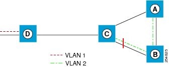
Figure 1. Flush Containment
These stages describe how flush containment affects topology change handling.
Topology change event: When a link fails (for example, link AB goes down), device C responds by activating its previously blocked port.
Traditional notification: In standard operation, device C sends a topology change notification (TCN) on all its other interfaces, including toward device D. This action causes MAC address flushes even for VLANs that are not impacted by the change (for example, VLAN 1 on device D).
Flush containment operation: With flush containment active, device C suppresses TCN messages on interfaces that do not carry VLANs belonging to the affected MSTI. In this scenario, no notification is sent from C to D, so MAC flushes do not occur for VLAN 1 on D.
Resulting limitation of flush scope: Only those sections of the network carrying the affected MSTI (the right-hand side with A, B, and C in the example) process the MAC address flush.
Bringup delay for MSTP interfaces
Bringup delay is a Cisco feature that prevents MSTP (Multiple Spanning Tree Protocol) from considering an interface in the spanning tree calculation until the interface is fully ready to forward traffic. This feature is especially useful when a line card initially boots up, as the system may declare its interfaces as "up" before the data plane is actually able to forward traffic. According to the MSTP standard, interfaces are included in the calculation as soon as they are declared up, which can result in other interfaces being moved into the blocking state if the newly started interfaces are erroneously selected.
The bringup delay addresses this issue by introducing a configurable delay period when MSTP-configured interfaces first come into existence, such as after a card reload. During this delay, the interfaces remain in the blocking state and are excluded from spanning tree calculations until they are truly ready to forward traffic. It is important to note that bringup delay only applies when new MSTP-configured interfaces are created; if MSTP is later configured on an existing interface, no delay is applied.