The documentation set for this product strives to use bias-free language. For the purposes of this documentation set, bias-free is defined as language that does not imply discrimination based on age, disability, gender, racial identity, ethnic identity, sexual orientation, socioeconomic status, and intersectionality. Exceptions may be present in the documentation due to language that is hardcoded in the user interfaces of the product software, language used based on RFP documentation, or language that is used by a referenced third-party product. Learn more about how Cisco is using Inclusive Language.
Media Redundancy Protocol (MRP), defined in International Electrotechnical Commission (IEC) standard 62439-2, provides fast
convergence in a ring network topology for Industrial Automation networks. MRP Media Redundancy Manager (MRM) defines its
maximum recovery times for a ring in the following range: 200 ms and 500 ms.
Note
The default maximum recovery time on the Cisco IE switch is 200 ms for a ring composed of up to 50 nodes. You can configure
the switch to use the 500 ms recovery time profile as described in Configure MRP Auto-Manager. The 10 ms and 30 ms recovery time profiles are not supported.
MRP operates at the MAC layer and is commonly used in conjunction with the PROFINET standard for industrial networking in
manufacturing.
MRP Mode
MRP is supported on the switches.
MRP CLI mode is managed by the Cisco IOS XE CLI and WebUI, a web-based user interface (UI).
Note
When managing the switch in MRP CLI mode, you cannot download the MRP configuration from Siemens STEP7/TIA.
Protocol Operation
In an MRP ring, the MRM serves as the ring manager, while the Media Redundancy Clients (MRCs) act as member nodes of the
ring. Each node (MRM or MRC) has a pair of ports to participate in the ring. The MRM initiates and controls the ring topology
to react to network faults by sending control frames on one ring port over the ring and receiving them from the ring over
its other ring port, and conversely in the other direction. An MRC reacts to received reconfiguration frames from the MRM
and can detect and signal link changes on its ring ports.
On the switch, certain nodes or all nodes in the ring can also be configured to start as a Media Redundancy Automanager (MRA).
MRAs select one MRM among each other by using a voting protocol and a configured priority value. The remaining MRAs transition
to the MRC role.
All MRM and MRC ring ports support the following states:
Disabled: Ring ports drop all received frames.
Blocked: Ring ports drop all received frames except MRP control frames and some standard frames, for example, LLDP.
Forwarding: Ring ports forward all received frames.
Not Connected: The link is physically down or disconnected. (This state differs from the Disabled state, in which the MRP
Port is manually disabled through software.)
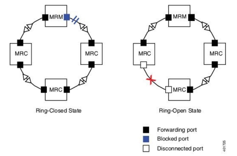
During normal operation, the network operates in the Ring-Closed state (see figure below). To prevent a loop, one of the
MRM ring ports is blocked, while the other port is forwarding. Most of the time, both ring ports of all MRCs are in the forwarding
state. With this loop avoidance, the physical ring topology becomes a logical stub topology.
In the figure, note the following details about the two rings, left and right:
Left Ring: The connection (small blue square, top) on the MRM is in a blocked state (as shown by the two parallel lines)
because no ports are disconnected.
Right Ring: Two MRC connections (left and center small white squares) are in the disabled state because the link between them
is broken, as marked by a red “x”.
Figure 1. MRP Ring States
If a network failure occurs:
The network shifts into the Ring-Open state.
In the case of failure of a link connecting two MRCs, both ring ports of the MRM change to the forwarding state, the MRCs
adjacent to the failure have a disabled and a forwarding ring port, and the other MRCs have both ring ports forwarding.
In the Ring-Open state, the network logical topology becomes a stub.
Layer 2 Ethernet frames will be lost during the time required for the transition between these two ring states. The MRP protocol
defines the procedures to automatically manage the switchover to minimize the switchover time. A recovery time profile, composed
of various parameters, drives the MRP topology convergence performance. The 200 ms profile supports a maximum recovery time
of 200 ms.
MRP uses three types of control frames:
To monitor the ring status, MRM regularly sends test frames on both ring ports.
When MRM detects failure or recovery, it sends TopoChange frames on both ring ports.
When MRC detects failure or recovery on a local port, it sends LinkChange subtype frames, Linkdown and Linkup, to the MRM.
Media Redundancy Automanager
If configured to start as a Media Redundancy Automanager (MRA), the node or nodes select an MRM using a voting protocol and
configured priority value. The remaining MRAs transition to the MRC role. All nodes must be configured as MRA. A manually
configured MRM and MRA in the same ring is not supported.
Although MRAs transition to the MRC role after an MRM is selected, you cannot explicitly configure an MRC.
The MRA role is not an operational MRP role like MRM or MRC. It is only an administrative, temporary role at device startup,
and a node must transition to the MRM role or the MRC role after startup and the MRM is selected though the manager voting
process.
MRA functions as follows:
At power on, all MRAs begin the manager voting process. Each MRA begins to send MRP_Test frames on both ring ports. The MRP_Test
frame contains the MRA's priority value. The remote manager's priority value contained in the received MRP_Test frames are
compared with the MRA's own priority. If its own priority is higher than the received priority, the MRA sends a negative test
manager acknowledgment (MRP_TestMgrNAck) frame, along with the remote manager's MAC address.
If the receiving MRA receives an MRP_TestMgrNAck with its own MAC address, the receiving MRA initiates the transition into
the client (MRC) role.
The MRP_TestPropagate frame informs other MRA devices in the client role about the role change and the new higher priority
manager. The clients receiving this frame update their higher priority manager information accordingly. This ensures that
clients remain in the client role if the monitored higher priority manager role changes.
Licensing
You do not need a feature license to use MRP with Switches. MRP works with either base license—Network Essentials or Network
Advantage.
To find information about platform support and to know which license levels a feature is available with, use Cisco Feature
Navigator. To access Cisco Feature Navigator, go to https://www.cisco.com/go/cfn. An account on cisco.com is not required.
Multiple MRP Rings
In an Industrial Ethernet network, an MRP ring in a cell/area is a sub-ring of the access layer. You can connect multiple
MRP rings, which you can then aggregate into the distribution layer.
You can configure up to 3 rings. The MRP switch can be configured only as an auto-manager.
MRP-STP Interoperability
MRP works with Spanning Tree Protocol (STP) to prevent unwanted broadcast loops in the event that a user accidentally connects
a device that does not participate in the MRP ring. In a network operating with MRP and STP, spanning tree bridge protocol
data units (BPDUs) are not sent on MRP-enabled ports. If ports are unconfigured from an MRP ring, then the ports are added
to the spanning tree.
MRP-STP interoperability is supported in MRP CLI mode, and functions without additional CLI configuration.
Prerequisites
Because MRP is deployed in a physical Ring topology, before configuring or unconfiguring the MRP feature, it is advised to
leave one physical connection between two nodes in each ring open by either issuing a shut command on the connecting interfaces or physically removing the cable to avoid any network storms. After you have properly
configured all MRMs, issue a noshut command on the port or re-connect the cable between the nodes.
Guidelines and Limitations
General Guidelines and Limitations
To avoid Smart License registration failure, ensure that the NTP configuration and the device clock are in sync.
Support for multiple MRP rings is available only through the CLI or WebUI.
The switch supports up to 50 MRCs per ring.
MRP cannot run on the same interface (port) as Resilient Ethernet Protocol (REP), Device Level Ring (DLR), Spanning Tree Protocol
(STP), Flex Links, macsec, or Dot1x.
For access ports, you must specifically configure switchportmodeaccess and switchportaccessvlanx commands in the MRP interface.
MRP interfaces come up in a forwarding state and remain in a forwarding state until notified that it is safe to block. The
MRP ring state changes to Ring-Closed.
MRP ports cannot be configured as any of these port types: SPAN destination port, Private VLAN port, or Tunnel port.
MRP is not supported on EtherChannels or on an individual port that belongs to an EtherChannel.
Each MRP ring can have one MRP VLAN. The VLAN must be different for each ring in a device to avoid traffic flooding.
MRP CLI Mode Guidelines and Limitations
After using the CLI to configure the MRP ring, you must attach the MRP ring to a pair of ports that support MRP.
Both MRP ports must have the same interface mode (access or trunk).
To change an existing MRP ring's configuration (mode), or to change the interface mode of the ring ports between access and
trunk, you must first delete the ring and then recreate it with the new configuration.
When both MRP ports are in access mode, the access VLANs should match. If the configured MRP VLAN does not match the ports'
access VLAN, the MRP VLAN is automatically changed to the MRP ports’ access VLAN.
In an MRP ring with two access ports, if the ports do not belong to the same access VLAN when you create the MRP ring or
you change the access VLAN for only one of the ports after the MRP ring is created, the MRP ring operation is suspended and
a message similar to the following is displayed:
ERROR% The ring 1 ports don't belong to the same access VLAN. The MRP ring will not function until the issue has been fixed
Resolve the issue by configuring the access VLAN to be the same for the two ring ports.
The 200 ms standard profile and 500 ms profile are supported. The 10 ms profile and 30 ms profile are not supported.
You can activate MRA through the CLI.
Although MRAs transition to the MRC role after an MRM is selected, you cannot explicitly configure an MRC.
Default Settings
MRP is disabled by default; MRP CLI is the default mode when MRP is enabled.
The default VLAN is 1.
Note
Create the non-default VLAN before you assign it to MRP ring 1.
Guidelines and limitations to PROFINET MRP mode
Before configuring the Cisco switch with PROFINET MRP through Siemens TIA or STEP7, ensure the following:
The PROFINET MRP feature does not support the MRC role.
Use the TIA portal to configure or modify the MRA role.
Avoid using the CLI for configuration when TIA is in use. MRP CLI mode and PROFINET MRP mode are mutually exclusive.
If the switch is connected to the PROFINET PLC, the output of show profinet status | include Connected should appear Yes . If it shows No , the switch is not connected to the PROFINET PLC.
Ensure that the GSD file version matches the Cisco IOS release to avoid compatibility issues. Refer to the PROFINET Protocol Configuration Guide for detailed configuration instructions.
Install the PROFINET GSD File
The PROFINET MRP GSD file is bundled with the Cisco IOS XE software release. After the switch boots at least one time, the
GSD files for the switch are located in a directory called "ProfinetGSD". In this directory, there is a zip file containing
all the GSDs for all the switch SKUs. Use the GSD file bundled with the release and included in the ProfinetGSD directory.
Note
Remove the older GSD XML file from TIA 15 or STEP 7 to ensure compatibility with the Cisco IOS software.
Configure PROFINET MRP
This task guides you through configuring PROFINET MRP to ensure proper network operation and redundancy.
Before you begin
Disconnect an MRP Ethernet port from the ring (open ring) to discover all neighboring devices using the LLDP protocol. Perform
this step before deploying PROFINET MRP to the network. This approach prevents unnecessary flooding if configuration issues
occur.
(Optional) Verify Neighbor Discovery with LLDP.
Use the command show lldp neighbor to confirm all neighbor devices are correctly discovered before continuing with PROFINET MRP setup.
Check that the PROFINET status indicates a connected-state.
Inspect the MRP ring port status:
Use the profinet mrp ring 1 command.
Procedure
Step 1
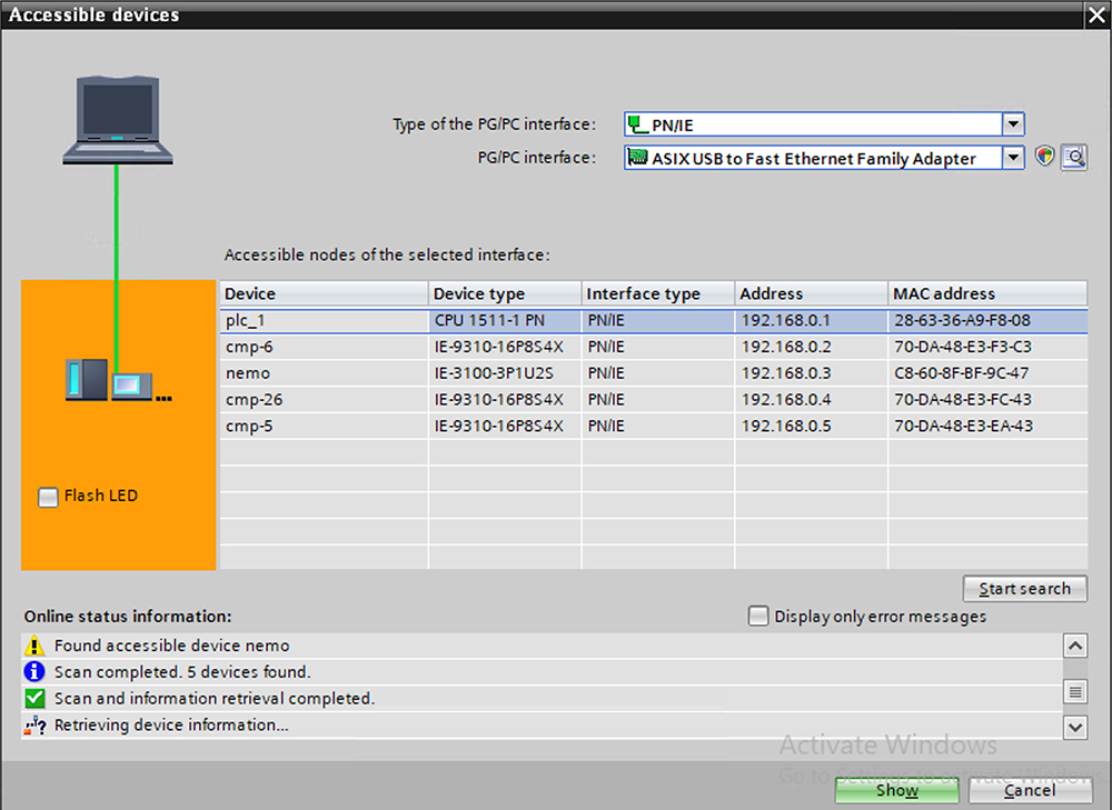
Access the PROFINET Device Discovery (DCP) window.
Open the PROFINET DCP window to identify and manage devices in the network.
Figure 2. PROFINET Device Discovery (DCP) window before configuring MRP
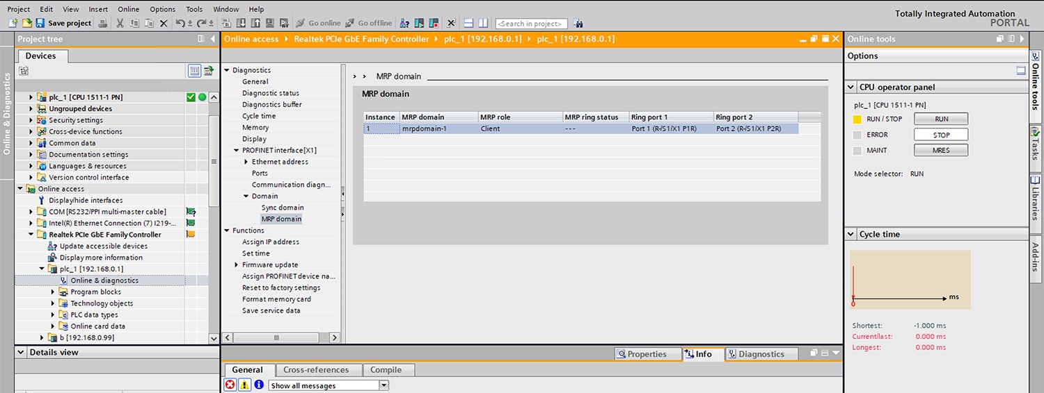
Step 2
Assign PROFINET MRP Manager role and domain name on MRM device.
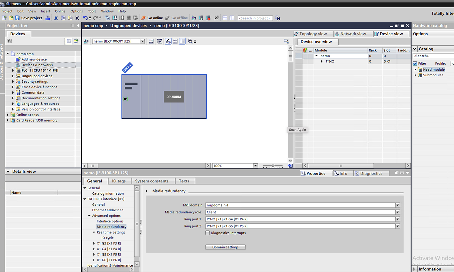
Figure 3. PROFINET MRP Manager role and MRP domain name
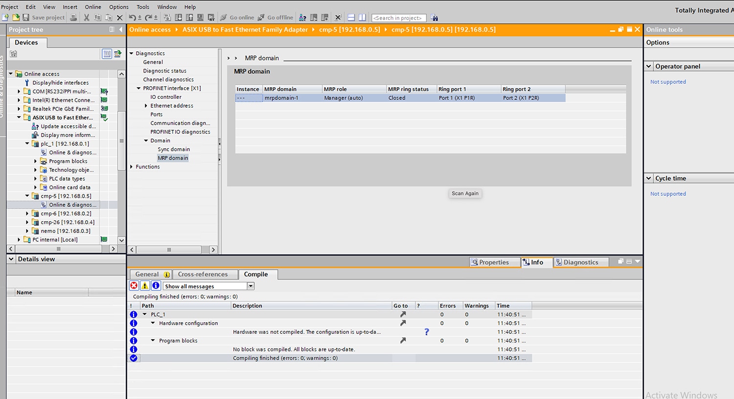
Step 3
Define the PROFINET MRP client and MRP domain name on client devices.
Figure 4. PROFINET MRP and MRP domain on client
Step 4
When using MRA mode, configure all devices and domain details.
Step 5
Configure the PROFINET MRP interfaces on all devices participating in the ring.
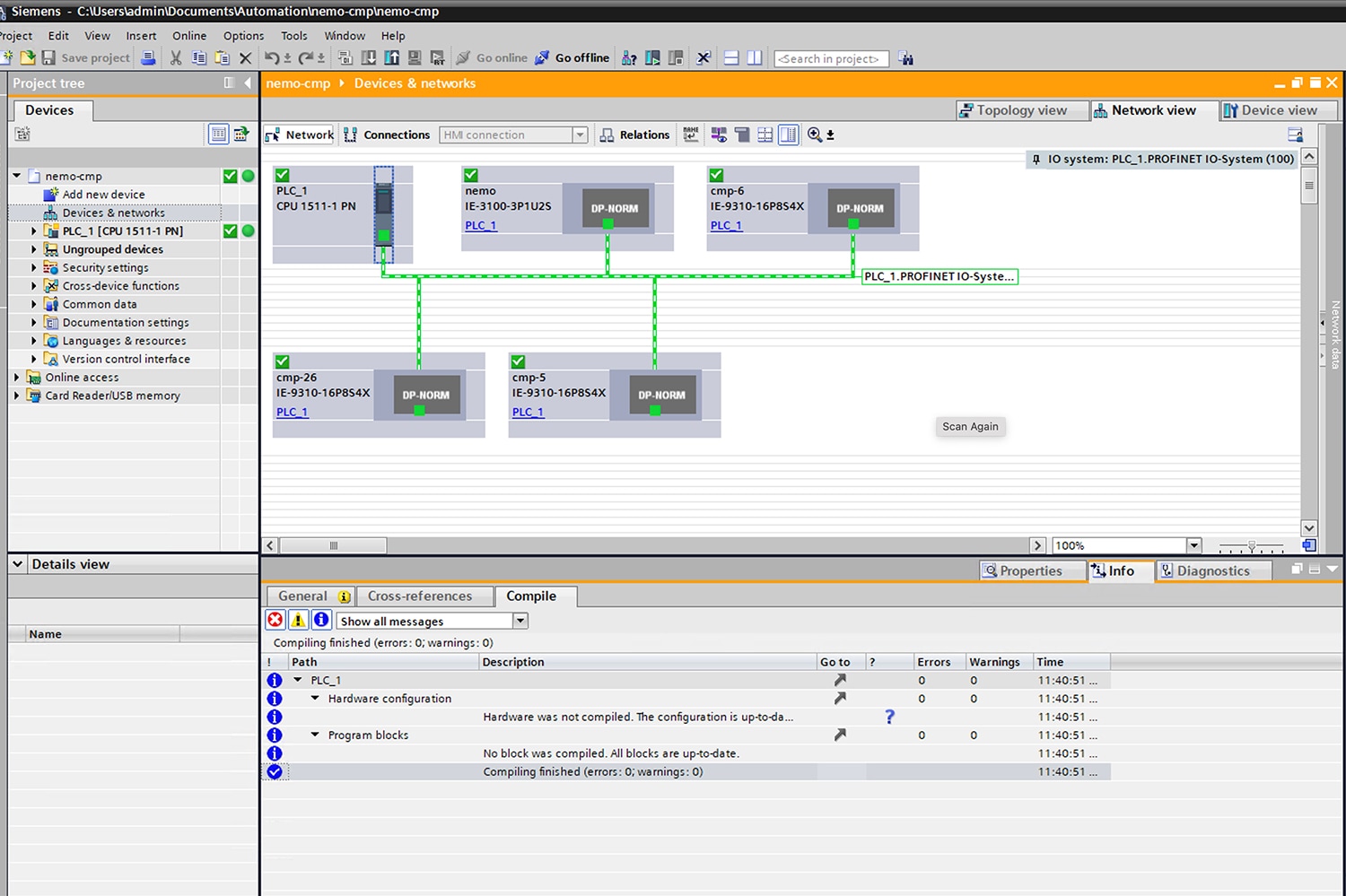
Figure 5. PROFINET MRP inerfaces
Step 6
Compile the configuration, and then download it to the PLC device.
Step 7
Verify that all devices are connected and the MRP ring is closed.
Verify on the devices that the MRP ring is closed by using the show profinet mrp ring 1 command:
Ensure that one port is in the Blocked state and the other port is in the Forwarding state.
Managing PROFINET Using Simatic Step 7 or TIA 15 Portal
This section provides an overview of key screens within the TIA portal. It does not provide any configuration details. For
details on using the TIA portal, refer to the Siemens Simatic STEP7 user documentation.
Note
MRP automanager in PROFINET mode is supported only in TIA V15.
To configure MRP, configure the node as MRA and specify the two MRP ports. Starting with Cisco IOS XE release 26.2.1, you
can configure up to 12 rings on the device (the device can be manager or client) with a manager instance for each ring and
one manager per device.
These MRP configuration parameters are optional:
domain-id: A unique ID that represents the MRP ring.
domain-name: Logical name of the configured MRP domain-ID.
profile: 200 ms (the default)
vlan-id: VLAN for sending MRP frames.
Configure MRP Auto-Manager
Perform this procedure to configure the switch as MRA in MRP CLI mode, which is the default.
Note
If the device is connected to a PLC module, ensure
no device in the ring
is selected for MRP.
Procedure
Step 1
Use the
configure terminal
command to enter global configuration mode.
Example:
Switch# configure terminal
Step 2
Configure MRP
Use the no profinet mrp command to disable PROFINET MRP.
Example:
Switch# no profinet mrp
Use the mrp ringmrp_id command to enable MRP.
Example:
Switch(config)# mrp ring 1
Starting from Cisco IOS XE release 26.1.1, MRP supports up to 12 rings.
Step 3
Configure Auto-Manager mode and domain parameters
Use the mode auto-manager command to configure MRP auto-manager mode on the switch.
Example:
Switch(config-mrp)# mode auto-manager
(Optional for single MRP ring) Use the domain-iddomain_value command to configure the domain ID.
(Optional) Use the vlan-idvlan command to configure the VLAN ID.
Example:
Switch(config-mrp-auto-manager)# vlan-id 10
Step 4
Configure Recovery Profile, Priority, and Interval
(Optional) Use the profile { 30 | 200 | 500 } command to configure the recovery profile.
Example:
Switch(config-mrp-auto-manager)# profile 200 ms
30: Maximum recovery time 30 milliseconds.
200: Maximum recovery time 200 milliseconds.
500: Maximum recovery time 500 milliseconds.
Starting from Cisco IOS XE release 26.1.1, MRP profile supports 30 ms also.
(Optional) Use the priorityvalue command to configure the MRA priority.
Example:
Switch(config-mrp-auto-manager)# priority 40960
value : Range <36864 – 61440>, lowest: 65535.
The default priority is 40960.
(Optional) Use the intervalinterval command to configure the interval.
Example:
Switch(config-mrp-auto-manager)# interval 3
3: 3 milliseconds MRP_Test default interval for 30 ms profile.
20: 20 milliseconds MRP_Test default interval for 200 ms profile.
50: 50 milliseconds MRP_Test default interval for 500 ms profile.
<3-10>: Optional faster MRP_Test interval in milliseconds.
Note
The Interval field is not displayed in WebUI for MRP.
The optional faster MRP_Test interval can be configured only when the ring is formed with IE3500 devices.
Use the exit command to return to global configuration mode.
Example:
Switch(config-mrp-auto-manager)# exit
Step 5
Configure the ring ports
Use the interfaceinterface-id command to specify the ID of the port that serves as the first ring port.
Example:
Switch(config)# interface GigabitEthernet1/1
Use the switchport mode { access | trunk } command to configure the interface mode.
Example:
Switch(config-if)# switchport mode access
You must specify switchport mode access when configuring MRP in access mode.
Use the mrp ringring_id command to associate the interface to the MRP ring.
Example:
Switch(config-if)# mrp ring 1
Step 6
Use the end command to return to privileged EXEC mode.
Example:
Switch(config-mrp-auto-manager)# end
Step 7
(Optional) Use the show mrp ringring_id command to monitor the MRP ring configuration.
Example:
Switch# show mrp ring 1
MRP ring 1
Profile : 30 ms
Mode : Auto-Manager
Priority : 40960
Operational Mode: manager
From : CLI
License : Active
Best Manager :
MAC Address : 00:78:88:5E:03:81
Priority : 36864
Network Topology: Ring
Network Status : Closed
Port1: Port2:
MAC Address :84:B8:02:ED:E8:02 MAC Address :84:B8:02:ED:E8:01
Interface :GigabitEthernet1/1 Interface :GigabitEthernet1/2
Status :Forwarding Status :Forwarding
VLAN ID : 10
Domain Name : Cisco MRP Ring 1
Domain ID : FFFFFFFF-FFFF-FFFF-FFFF-FFFFFFFFFFFF
Topology Change Request Interval : 10ms
Topology Change Repeat Count : 3
Short Test Frame Interval : 10ms
Default Test Frame Interval : 20ms
Test Monitoring Interval Count : 3
Test Monitoring Extended Interval Count : N/A
Note
When the switch is operating in CLI mode and PROFINET mode, the show mrp ring output shows License: Not Applicable
Step 8
Use the show mrp ports command to monitor MRP port status.
Example:
Switch# show mrp ports
Ring ID : 1
PortName                Status
--------------------------------------
GigabitEthernet1/1         Forwarding
GigabitEthernet1/2         Blocked
Configuration Example
The following example shows the MRP switch configured as automanager:
Switch#configure terminal
Switch# no profinet mrp
Enter configuration commands, one per line. End with CNTL/Z.
Switch(config)#mrp ring 1
Switch(config-mrp)#mode auto-manager
Switch(config-mrp-auto-manager)#priority 36864
Switch(config-mrp-auto-manager)#end
Switch#configure terminal
Enter configuration commands, one per line. End with CNTL/Z.
Switch(config)#interface gi1/1
Switch(config-if)#switchport mode trunk
Switch(config-if)#mrp ring 1
WARNING% Enabling MRP automatically set STP FORWARDING. It is recommended to shutdown all interfaces which are not currently in use to prevent potential bridging loops.
Switch(config-if)#exit
Switch(config)#interface gi1/2
Switch(config-if)#switchport mode trunk
Switch(config-if)#mrp ring 1
WARNING% Enabling MRP automatically set STP FORWARDING. It is recommended to shutdown all interfaces which are not currently in use to prevent potential bridging loops.
Switch(config-if)#end

Switch#show mrp ring
MRP ring 1

Profile     : 200 ms
Mode        : Auto-Manager
Priority    : 36864
Operational Mode: Manager
From        : CLI
License     : Active
Best Manager MAC Address    :84:B8:02:ED:E8:01     priority 36864

Network Topology: Ring
Network Status  : OPEN
Port1:                                     Port2:
 MAC Address    :84:B8:02:ED:E8:02          MAC Address    :84:B8:02:ED:E8:01
 Interface      :GigabitEthernet1/1      Interface      :GigabitEthernet1/1
 Status         :Forwarding                 Status         :Forwarding

VLAN ID     : 1
Domain Name : Cisco MRP Ring 1
Domain ID   : FFFFFFFF-FFFF-FFFF-FFFF-FFFFFFFFFFFF

Topology Change Request Interval        : 10ms
Topology Change Repeat Count            : 3
Short Test Frame Interval               : 10ms
Default Test Frame Interval             : 20ms
Test Monitoring Interval Count          : 3
Test Monitoring Extended Interval Count : N/A


Topology Change Request Interval        : 10ms
Topology Change Repeat Count            : 3
Short Test Frame Interval               : 10ms
Default Test Frame Interval             : 20ms
Test Monitoring Interval Count          : 3
Test Monitoring Extended Interval Count : N/A
Verifying the Configuration
You can use the following commands to verify the MRP configuration.
Command
Description
showmrpring?{1-22}
Display details about the MRP ring configuration.
showmrpports
Display details about the MRP port states. If MRP is not configured on any ports, display shows N/A.
manager is available only when the switch is configured as manager or automanager.
showtech-supportmrp
Display all MRP details.
Feature History
Table 1. Feature history
Feature Name
Releases
Description
Media Redundancy Client
Cisco IOS XE 26.1.1
This feature enables configuring Cisco switches as Media Redundancy Clients (MRC) within an MRP ring, allowing them to participate
in network redundancy and respond to topology changes without acting as the ring manager. This approach enhances network resiliency
and simplifies deployment, supporting rapid failover and compliance with industrial certification requirements.

 Feedback