Parallel Redundancy Protocol

Information About PRP

From Release 17.17.1, the Cisco IE3505 Rugged Series Switches and IE3505 Heavy-Duty Series Switches supports Parallel Redundancy Protocol (PRP).

Parallel Redundancy Protocol overview

PRP is defined in the International Standard IEC 62439-3. PRP is designed to provide hitless redundancy (zero recovery time after failures) in Ethernet networks.

To recover from network failures, redundancy can be provided by network elements connected in mesh or ring topologies using protocols like RSTP, REP, or MRP, where a network failure causes some reconfiguration in the network to allow traffic to flow again (typically by opening a blocked port). These schemes for redundancy can take between a few milliseconds to a few seconds for the network to recover and traffic to flow again.

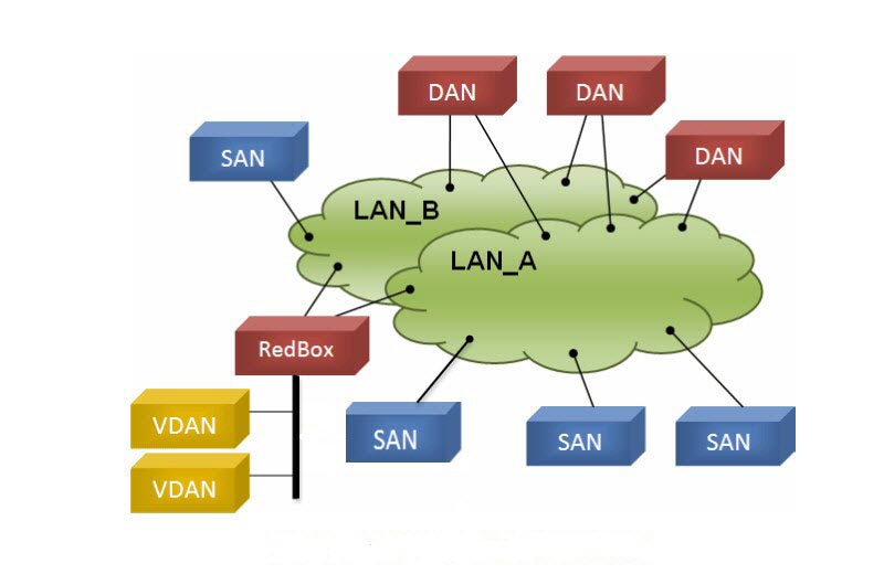
PRP uses a different scheme, where the end nodes implement redundancy (instead of network elements) by connecting two network interfaces to two independent, disjointed, parallel networks (LAN-A and LAN-B). Each of these Dually Attached Nodes (DANs) then have redundant paths to all other DANs in the network.

The DAN sends two packets simultaneously through its two network interfaces to the destination node. A redundancy control trailer (RCT), which includes a sequence number, is added to each frame to help the destination node distinguish between duplicate packets. When the destination DAN receives the first packet successfully, it removes the RCT and consumes the packet. If the second packet arrives successfully, it is discarded. If a failure occurs in one of the paths, traffic continues to flow over the other path uninterrupted, and zero recovery time is required.

Non-redundant endpoints in the network that attach only to either LAN-A or LAN-B are known as Singly Attached Nodes (SANs).

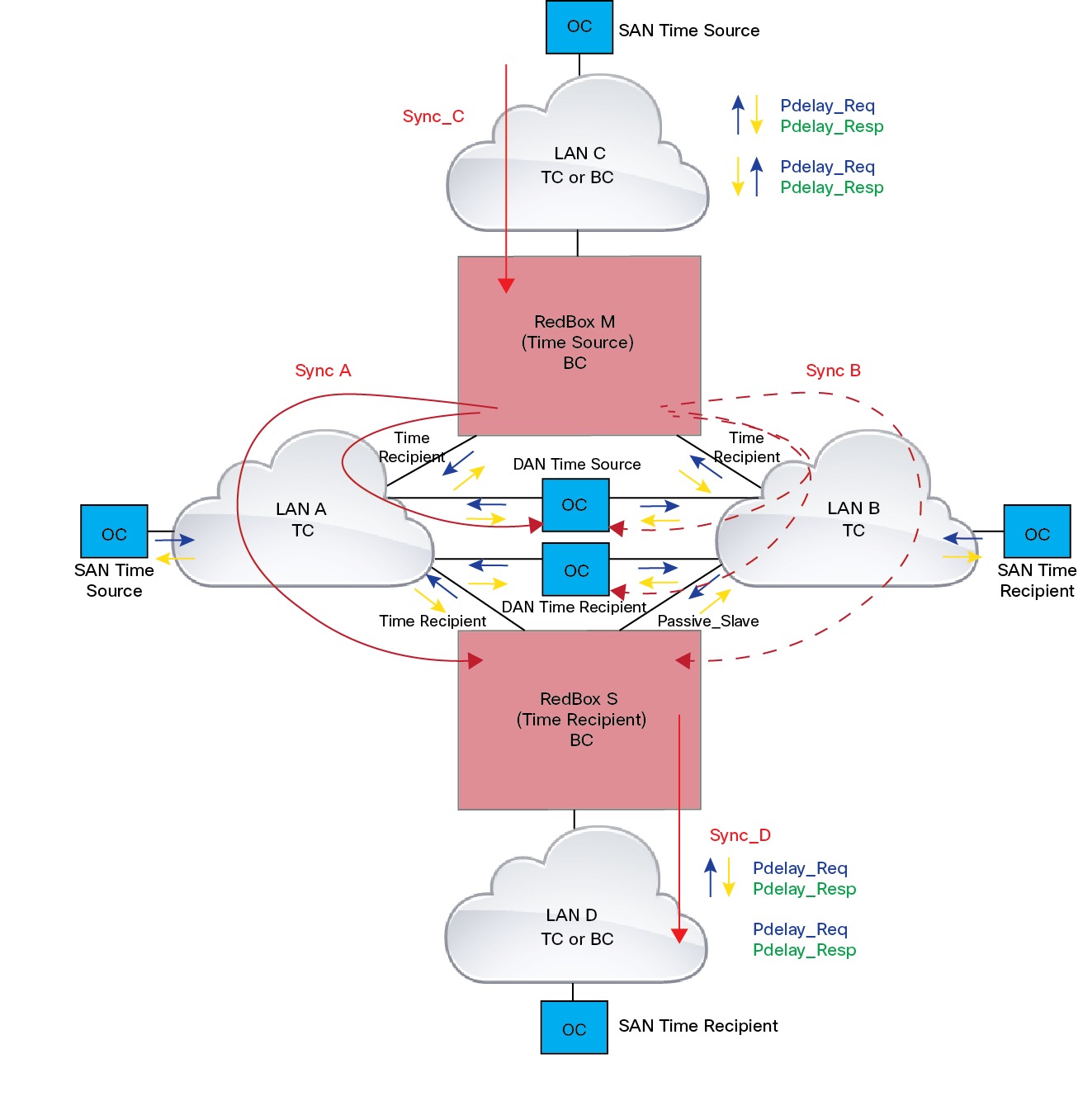
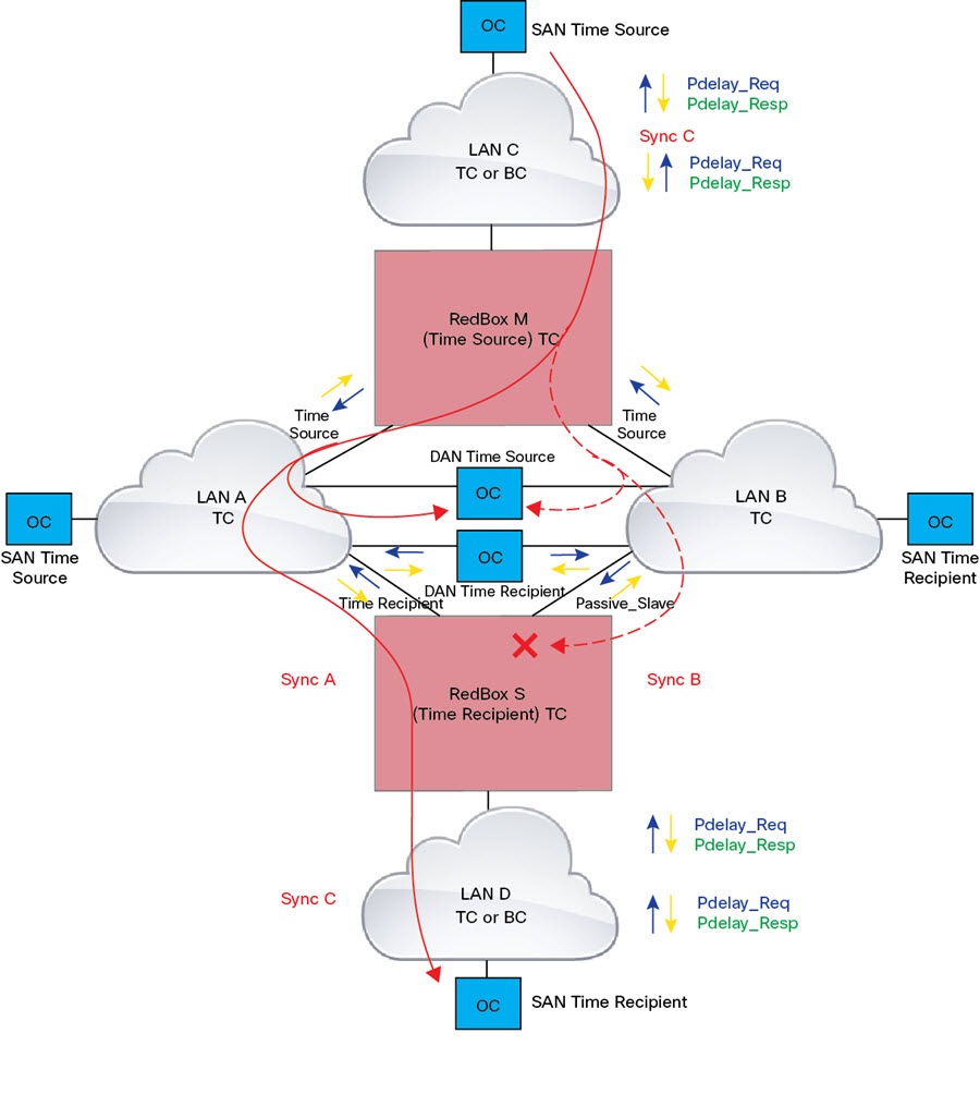
A Redundancy Box (RedBox) is used when an end node that does not have two network ports and does not implement PRP needs to implement redundancy. Such an end node can connect to a RedBox, which provides connectivity to the two different networks on behalf of the device. Because a node behind a RedBox appears for other nodes like a DAN, it is called a Virtual DAN (VDAN). The RedBox itself is a DAN and acts as a proxy on behalf of its VDANs.

Figure 1. PRP Redundant Network

To manage redundancy and check the presence of other DANs, a DAN periodically sends Supervision frames and can evaluate the Supervision frames sent by other DANs.

Switches that Support PRP

Table 1. The following Advanced base modules SKUs (PIDs) supports PRP.

Switch

PID

Cisco IE3505 Rugged Series Switch

IE-3505-8P3S

IE-3505-8T3S

Cisco IE3505 Heavy-Duty Series Switch

IE-3505H-16T

Table 2. The following Expansion modules PIDs include PRP support when installed on one of the above advanced base modules

Switch

Expansion modules PID

Cisco IE3505 Rugged Series Switch

IEM-3500-14T2S

IEM-3500-6T2S

IEM-3500-16P

IEM-3500-16T

IEM-3500-8P

IEM-3500-8S

IEM-3500-8T

Support for PRP is available on Network Essentials and Network Advantage licenses.

Supported PRP Features

IE-3505-8P3S, IE-3505-8T3S, and IE-3505H-16T switches support the following PRP features.

PRP supports maximum of two channel instance as shown in the following table:

Table 3. PRP Support for Cisco IE3505 Series Switch and Expansion Models

Switch

FPGA Profile

Number of PRP Instance

Cisco IE3505 Rugged Series without expansion module

Default

1

Redundancy

2

Cisco IE3505 Rugged Series with expansion module

Default

1

Redundancy

2

IE-3505H-16T

Default

1

Redundancy

2

Role of the Switch

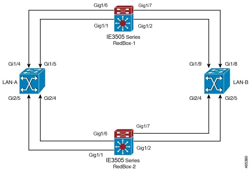
The switches implement RedBox functionality using Gigabit Ethernet port connections to each of the two LANs.
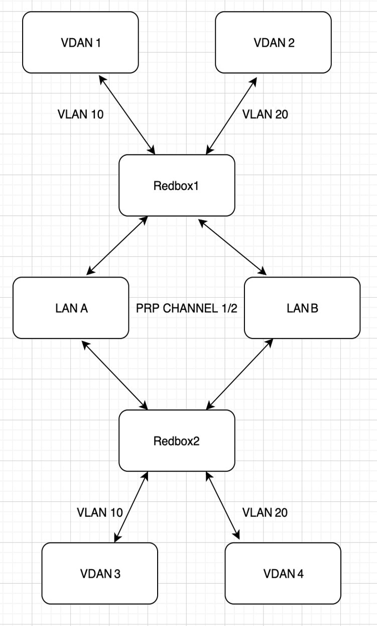
PRP Channels

PRP channel or channel group is a logical interface that aggregates two Gigabit Ethernet interfaces (access, trunk, or routed) into a single link. In the channel group, the lower numbered Gigabit Ethernet member port is the primary port and connects to LAN-A. The higher numbered port is the secondary port and connects to LAN-B.

The PRP channel remains up as long as at least one of these member ports remains up and sends traffic. When both member ports are down, the channel is down. The maximum number of supported PRP channel groups per switch is 2, depending on the configured FPGA profile. For information about FPGA profile, see Configure FPGA Profile.

The interfaces that you can use for each group on each switch series are fixed, as shown in the following table.

Table 4. The supported PRP channel interfaces for IE3505 Rugged Series Switch

PRP Channel Number

Module

Ports Interface

PRP Channel 1

Base module with SFP ports

GigabitEthernet1/1 and 1/2

PRP Channel 1

Base module with Copper (CU) ports

GigabitEthernet1/4 and 1/5

PRP Channel 2

Base module with CU ports

GigabitEthernet1/6 and 1/7

PRP Channel 2

8 port CU expansion module

GigabitEthernet2/1 and 2/2

PRP Channel 2

8 port SFP expansion module

GigabitEthernet2/1 and 2/2

PRP Channel 2

16 port CU expansion module

GigabitEthernet2/1 and 2/2

PRP Channel 2

8 port Mix expansion module

GigabitEthernet2/7 and 2/8

PRP Channel 2

16 port Mix expansion module

GigabitEthernet2/15 and 2/16

Table 5. The supported PRP channel interfaces for advanced IE3505 Heavy Duty Series Switch

PRP Channel Number

Module

PRP Channel 1

Base module with CU ports

GigabitEthernet1/1 and 1/2

PRP Channel 1

Base module with CU ports

GigabitEthernet1/4 and 1/5

PRP Channel 2

Base module with CU ports

GigabitEthernet1/6 and 1/7

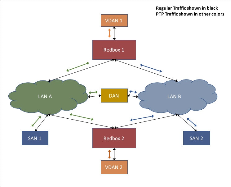
Mixed Traffic and Supervision Frames

Traffic egressing the RedBox PRP channel group can be mixed, that is, destined to either SANs (connected only on either LAN-A or LAN-B) or DANs. To avoid duplication of packets for SANs, the switch learns source MAC addresses from received supervision frames for DAN entries and source MAC addresses from non-PRP (regular traffic) frames for SAN entries and maintains these addresses in the node table. When forwarding packets out the PRP channel to SAN MAC addresses, the switch looks up the entry and determines which LAN to send to rather than duplicating the packet.

A RedBox with VDANs needs to send supervision frames on behalf of those VDANs. For traffic coming in on all other ports and going out PRP channel ports, the switch learns source MAC addresses, adds them to the VDAN table, and starts sending supervision frames for these addresses. Learned VDAN entries are subject to aging.

You can add static entries to the node and VDAN tables as described in x. You can also display the node and VDAN tables and clear entries. See y and z.

VLAN Tag in Supervision Frame

Switches support VLAN tagging for supervision frames. PRP VLAN tagging requires that PRP interfaces be configured in trunk mode. This feature allows you to specify a VLAN ID in the supervision frames for a PRP channel.


Note


The IE3505 Series Switches support 512 VDAN/Node MAC addresses.

The PRP Supervision VLAN-aware feature is not supported in the IE3505 Series Switches.


For information on configuring the VLANs, see Configuring PRP Channel with Supervision Frame VLAN Tagging.

PTP over PRP

PRP provides high availability through redundancy for PTP. For a description of PTP, see Precision Time Protocol.

The PRP method of achieving redundancy by parallel transmission over two independent paths does not work for PTP as it does for other traffic. The delay that a frame experiences is not the same in the two LANs, and some frames are modified in the transparent clocks (TCs) while transiting through the LAN. A Dually Attached Node (DAN) does not receive the same PTP message from both ports even when the source is the same. Specifically:

  • Sync/Follow_Up messages are modified by TCs to adjust the correction field.

  • Boundary Clocks (BCs) present in the LAN are not PRP-aware and generate their own Announce and Sync frames with no Redundancy Control Trailer (RCT) appended.

  • Follow_Up frames are generated by every 2-step clock and carry no RCT.

  • TCs are not PRP-aware and not obliged to forward the RCT, which is a message part that comes after the payload.

Before support of PTP over LAN-A and LAN-B, PTP traffic was allowed only on LAN-A to avoid the issues with PTP and parallel transmission described earlier. However, if LAN-A went down, PTP synchronization was lost. To enable PTP to leverage the benefit of redundancy offered by the underlying PRP infrastructure, PTP packets over PRP networks are handled differently than other types of traffic.

The implementation of the PTP over PRP feature is based on the PTP over PRP operation that is detailed in IEC 62439-3:2016, Industrial communication networks - High availability automation networks - Part 3: Parallel Redundancy Protocol (PRP) and High-availability Seamless Redundancy (HSR). This approach overcomes the problems mentioned earlier by not appending an RCT to PTP packets and bypassing the PRP duplicate/discard logic for PTP packets.

PTP over PRP Packet Flow

The following figure illustrates the operation of PTP over PRP.

Figure 2. PTP over PRP Packet Flow

In the figure, VDAN 1 is the grandmaster clock (GMC). Dually attached devices receive PTP synchronization information over both their PRP ports. The LAN-A port and LAN-B port use a different virtual clock that is synchronized to the GMC. However, only one of the ports (referred to as time recipient) is used to synchronize the local clock (VDAN 2 in the figure). While the LAN-A port is the time recipient, the LAN-A port’s virtual clock is used to synchronize VDAN-2. The other PRP port, LAN-B, is referred to as PASSIVE. The LAN-B port’s virtual clock is still synchronized to the same GMC, but is not used to synchronize VDAN 2.

If LAN-A goes down, the LAN-B port takes over as the time recipient and is used to continue synchronizing the local clock on RedBox 2. VDAN 2 attached to RedBox 2 continues to receive PTP synchronization from RedBox 2 as before. Similarly, all DANs, VDANs, and RedBoxes shown in the figure continue to remain synchronized. For SANs, redundancy is not available, and in this example, SAN 1 loses synchronization if LAN-A goes down.

Due to the change, VDAN 2 may experience an instantaneous shift in its clock due to the offset between the LAN-A port’s virtual clock and the LAN-B port’s virtual clock. The magnitude of the shift should only be a few microseconds at the most, because both clocks are synchronized to the same GMC. The shift also occurs when the LAN-A port comes back as time recipient and the LAN-B port becomes PASSIVE.


Note


Cisco is moving from the traditional Master/Slave nomenclature. In this document, the terms Grandmaster clock (GMC) or time source and time recipient are used instead, where possible. Exceptions may be present due to language that is hard-coded in the user interfaces of the product software, language used based on RFP documentation, or language that is used by a referenced third-party product.


Supported Location of GMC

The GMC can be located in a PTP over PRP topology as one of the following:

  • A RedBox that is connected to both LAN A and LAN B (for example, RedBox 1 in the preceding diagram).

  • A VDAN (for example, VDAN 1 in the preceding diagram).

  • A DAN (for example, the DAN in the preceding diagram).

The GMC cannot be a SAN attached to LAN-A or LAN-B, because only the devices in LAN-A or LAN-B will be synchronized to the GMC.

Configuration

PTP over PRP does not require configuration beyond how you would normally configure PTP and PRP separately, and there is no user interface added for this feature. The difference is that before the PTP over PRP feature, PTP worked over LAN-A only; now it works over both LANs. Before implementing PTP over PRP, refer to Guidelines and Limitations.

The high-level workflow to implement PTP over PRP in your network is as follows:

  1. Refer to the section RedBox Types in this guide to determine the location of the PRP RedBox. Refer to Precision Time Protocol to determine the PTP mode and profile.

  2. Configure PTP as described in Precision Time Protocol and follow the procedure for the PTP profile determined in step 1.

  3. Configure PRP as described in Create a PRP Channel and Group.

Supported PTP Profiles and Clock Modes

The following table summarizes PTP over PRP support for the various PTP profiles and clock modes. In unsupported PTP profile/clock mode combinations, PTP traffic flows over LAN-A only. LAN-A is the lower numbered interface. See PRP Channels for PRP interface numbers.

PTP Profile

Clock Mode

Supported?

PRP RedBox type as per IEC 62439-3

End-to-End Delay Request-Response default profile BC Yes PRP RedBox as doubly attached BC (DABC) with E2E
E2E TC No PRP RedBox as doubly attached TC (DATC) with E2E
Power Profile BC Yes PRP RedBox as doubly attached BC (DABC) with P2P
P2P TC Yes PRP RedBox as doubly attached TC (DATC) with P2P

PRP RedBox Types

The switch plays the role of a RedBox in PRP networks. This section describes the types of PRP RedBoxes supported for PTP over PRP as defined in IEC 62439-3.

PRP RedBox as a Doubly Attached BC (DABC) with E2E

In the configuration shown below, two RedBoxes (for example, M and S) are configured as Boundary Clocks (BCs) that use the End-to-End delay measurement mechanism and IEEE1588v2 Default Profile. The Best Master Clock Algorithm (BMCA) on RedBox M determines port A and port B to be connected to the time source. The PTP protocol running on Redbox M treats both ports A and B individually as time source ports and sends out Sync and Follow_Up messages individually on both the ports.

Figure 3. PRP Redbox as DABC with E2E

On Redbox S, the regular BMCA operation determines port A to be a time recipient and port B to be PASSIVE. However, with the knowledge that ports A and B are part of the same PRP channel, port B is forced into PASSIVE_SLAVE state. Port A and Port B on Redbox S operate as follows:

  • Port A works as a regular time recipient port. It uses the end-to-end delay measurement mechanism to calculate delay and offset from the time source. Using the calculated delay and offset, it synchronizes the local clock.

  • Port B is in PASSIVE_SLAVE state. It uses the end-to-end delay measurement mechanism to calculate delay and offset from the time source.

    It is passive in the sense that it maintains the calculated delay and offset, but does not perform any operation on the local clock. Having the delay and offset information readily available equips it to seamlessly change its role to time recipient if there is loss of connectivity to the time source on port A.

PRP RedBox as Doubly Attached BC (DABC) with P2P

The following figure shows an example where Redbox M and Redbox S are configured to run in Power Profile as Boundary Clocks that use Peer-to-Peer (P2P) delay measurement mechanism. In this example, the GMC is the ordinary clock attached through LAN C. All the clocks are configured to run Peer-to-Peer Delay measurement and the peer delay is regularly calculated and maintained on every link shown in the figure.

The BMCA on Redbox M determines ports A and B to be connected to the time source. The PTP protocol running on Redbox M treats both ports A and B individually as time source ports and sends out Sync and Follow_Up messages individually on both the ports.

Figure 4. PRP Redbox as DABC with P2P

On Redbox S, the regular BMCA operation determines port A to be time recipient and port B to be PASSIVE. However, with the knowledge that ports A and B are part of the same PRP channel, port B is forced into PASSIVE_SLAVE state. Port A and Port B on Redbox S operate as follows:

  • Port A works as a regular time recipient port. It uses the Sync and Follow_Up messages along with their correction field to calculate the delay and offset from time source and synchronize the local clock. (Unlike an E2E BC, it does not need to generate Delay_Req messages because all the link delays and residence times along the PTP path are accumulated in the correction field of the Follow_Up messages).

  • Port B is in PASSIVE_SLAVE state. Like port A, it maintains the delay and offset from time source, but does not perform any operation on the local clock. Having all the synchronization information available enables it to seamlessly take over as the new time recipient in case port A loses communication with the GM.

PRP RedBox as Doubly Attached TC (DATC) with P2P

The following figure shows an example where Redbox M and Redbox S are configured to run in Power Profile mode as Transparent Clocks. In this example, the GMC is the ordinary clock attached through LAN C. All the clocks are configured to run Peer-to-Peer Delay measurement and the peer delay is regularly calculated and maintained on every link shown in the figure.

Redbox M and Redbox S run BMCA even though it is not mandatory for a P2P TC to run BMCA. On Redbox M, the BMCA determines ports A and B to be connected to the time source. Redbox M forwards all Sync and Follow_Up messages received on port C out of ports A and B.

Figure 5. PRP Redbox as DATC with P2P

On Redbox S, port A is determined to be time recipient and port B to be PASSIVE_SLAVE as described earlier. Port A and Port B on Redbox S operate as follows:

  • Port A works as a regular time recipient port. It uses the Sync and Follow_Up messages along with their correction field to calculate the delay and offset from time source and synchronize the local clock. (Unlike an E2E BC, it does not need to generate Delay_Req messages since all the link delays and residence times along the PTP path are accumulated in the correction field of the Follow_Up messages).

  • Like port A, port B maintains the delay and offset from time source, but does not perform any operation on the local clock. Having all the synchronization information available enables it to seamlessly take over as the new time recipient in case port A loses communication with the GMC.

LAN-A and LAN-B Failure Detection and Handling

Failures in LAN-A and LAN-B are detected and handled in the same way for all RedBox types that are described in PRP RedBox Types.

Using the example that is shown in PRP RedBox as DATC with P2P with the GMC as a SAN in LAN C, a failure in LAN-A or LAN-B pertaining to PTP can occur due to the following reasons:

  • A device within the LAN goes down.

  • A link within the LAN goes down resulting in loss of connectivity.

  • PTP messages are dropped within the LAN.

These events result in PTP Announce Receipt Timeout on RedBox S, which triggers the BMCA calculation. Refer to section 7.7.3.1 of the IEEE 1588v2 standard for details on Announce Receipt Timeout.

The BMCA, once invoked, changes the state of the PASSIVE_SLAVE port to time recipient and time recipient to PASSIVE_SLAVE or PASSIVE or FAULTY. The state changes are done atomically to avoid transient cases where there are two time recipient ports or two PASSIVE_SLAVE ports.

RedBox S now synchronizes to the GMC over the new time recipient port. The change to synchronization should be quick and seamless, unless the delays experienced by PTP packets on the two LANs are very different or if there are some non-PTP devices in the LANs.

The SAN time recipient in LAN D also sees this shift in the timing from RedBox S and must converge to the new clock. This is similar to a GMC change event for this clock, but as mentioned earlier, the change is usually seamless.

TrustSec on a PRP Interface

You can configure Cisco TrustSec (CTS) on member interfaces of a PRP channel.

Because TrustSec is supported only on physical interfaces, you cannot configure TrustSec on the logical PRP channel interface. A PRP channel includes two interfaces, for example, Gi1/1 and Gi1/2. To configure TrustSec on interfaces that are members of a PRP channel, ensure that the following conditions are met:

  • The Network Advantage license is required to use TrustSec.

  • Configure TrustSec on each interface first, before it is part of the PRP channel.

  • The TrustSec configuration on both PRP channel interfaces must be the same to allow inline tagging and propagation with LAN-A and LAN-B as expected.


Note


CTS + Security Association Protocol (SAP) and CTS + MACsec Key Agreement (MKA) methods are not supported over PRP interface.


Configuring TrustSec on a PRP Interface

This section provides examples for configuring TrustSec on a PRP interface. You can configure the PRP channel interfaces by configuring each individual interface or by using the interface range <>.

Valid Configuration

The following example shows configuring TrustSec on each interface, one at a time, and then making that individual interface part of a PRP channel.


switch#configure terminal
switch(config)#int gi1/1 
switch(config-if)#switchport mode access 
switch(config-if)#switchport access vlan 30 
switch(config-if)#cts manual 
switch(config-if-cts-manual)#policy static sgt 1000 trusted 
switch(config-if-cts-manual)#exit 
switch(config-if)#prp-channel-group 1 
Creating a PRP-channel interface PRP-channel 1 

switch(config-if)# 
switch(config-if)#int gi1/2 
switch(config-if)#switchport mode access 
switch(config-if)#switchport access vlan 30 
switch(config-if)#cts manual 
switch(config-if-cts-manual)#policy static sgt 1000 trusted 
switch(config-if-cts-manual)#exit 
switch(config-if)#prp-channel-group 1 
switch(config-if)#end

The following example shows configuring TrustSec on a range of interfaces and then making the interfaces part of a PRP channel.


switch#configure terminal
switch(config)#int range gi1/1-2 
switch(config-if-range)#switchport mode access switch
switch(config-if-range)#switchport access vlan 30 
switch(config-if-range)#cts manual 
switch(config-if-cts-manual)#policy static sgt 1000 trusted 
switch(config-if-cts-manual)#exit 
switch(config-if-range)#prp-channel-group 1 
Creating a PRP-channel interface PRP-channel 1

CTS and PRP Show Commands

This section lists show commands that you can use when configuring TrustSec on PRP member interfaces and examples of some command outputs:

  • show cts interface summary

  • show cts pacs

  • show cts interface <>

  • show cts role-based counters

  • show prp channel detail

  • show prp statistics ingressPacketStatistics

  • show prp statistics egressPacketStatistics

The following example show the output of the show cts interface summary command:

switch#show cts interface summary
CTS Interfaces
---------------------
Interface                      Mode    IFC-state dot1x-role peer-id    IFC-cache    Critical-Authentication
-----------------------------------------------------------------------------
Gi1/1                          MANUAL  OPEN      unknown    unknown    invalid  Invalid
Gi1/2                          MANUAL  OPEN      unknown    unknown    invalid  Invalid

R1#show cts pacs
AID: 51F577DCE176855650F2F5609418AC6
PAC-Info:
  PAC-type = Cisco Trustsec
  AID: 51F577DC7E176855650F2F5609418AC6
  I-ID: petra3400ipv4
  A-ID-Info: Identity Services Engine
  Credential Lifetime: 09:06:08 UTC Wed Nov 01 2023
PAC-Opaque: 000200B8000300010004001051F577DC7E176855650F2F5609418AC60006009C000301002BBB79441FEE97B0E0B339B9036F9C710000001364C8D
1A000093A8054BC5FA1780A24E23B60A4BFF46AF47A317EB20391BFCA6F0CAABA7F66393F05799A3B0EAB602B54749DCF7225A45FDDB1349A81977D857B9C3
1959A2B54CFC4505CD903D84394E69E5795D31543BB575FB8D51A6FA021FB5E6A0C296F8CA21318377688073516714125D38973D9BF2A66792E3AD1C0A05C3
E739CA1
Refresh timer is set for 12w4d
R1#show cts interface GigabitEthernet1/1
Global Dot1x feature is Disabled
Interface GigabitEthernet1/1:
    CTS is enabled, mode:    MANUAL
    IFC state:               OPEN
    Interface Active for 00:03:25.772
    Authentication Status:   NOT APPLICABLE
        Peer identity:       "unknown"
        Peer's advertised capabilities: ""
    Authorization Status:    SUCCEEDED
        Peer SGT:            30
        Peer SGT assignment: Trusted
    SAP Status:              NOT APPLICABLE
    Propagate SGT:           Enabled
    Cache Info:
        Expiration            : N/A
        Cache applied to link : NONE

    Statistics:
        authc success:              0
        authc reject:               0
        authc failure:              0
        authc no response:          0
        authc logoff:               0
        sap success:                0
        sap fail:                   0
        authz success:              0
        authz fail:                 0
        port auth fail:             0

    L3 IPM:   disabled.

The following example shows the output of the show cts role-based counters command:

switch# show cts role-based counters
Role-based IPv4 counters
From    To      SW-Denied  HW-Denied  SW-Permitt HW-Permitt SW-Monitor HW-Monitor
*       *       0          0          0          0          0          0
122     0       0          0          0          0          0          0
200     0       0          0          0          2845       0          0
201     130     0          0          0          0          0          0
130     200     0          0          0          2845       0          0

The following example shows the output of the show prp channel detail command:

switch#show prp channel 1 summary
Flags:  D - down        P - bundled in prp-channel
        R - Layer3      S - Layer2
        U - in use

Number of channel-groups in use: 1
Group  PRP-channel   Ports
------+-------------+----------------------------------------
1      PR1(SU)       Gi1/1(P), Gi1/2(P)

R1#show prp channel 1 detail
PRP-channel: PR1
------------
 Layer type = L2
 Ports: 2	Maxports = 2
 Port state = prp-channel is Inuse
 Protocol = Enabled
Ports in the group:
  1) Port: Gi1/1
   Logical slot/port = 1/1	Port state = Inuse
	Protocol = Enabled
  2) Port: Gi1/2
   Logical slot/port = 1/2	Port state = Inuse
	Protocol = Enabled

The following example shows the output of the show prp statistics ingressPacketStatistics command:

switch#sh prp statistics ingressPacketStatistics 
 PRP prp_maxchannel 2 INGRESS STATS:
 PRP channel-group 1 INGRESS STATS:
   ingress pkt lan a: 1010
   ingress pkt lan b: 1038
   ingress crc lan a: 0
   ingress crc lan b: 0
   ingress danp pkt acpt: 20
   ingress danp pkt dscrd: 20
   ingress supfrm rcv a: 382
   ingress supfrm rcv b: 390
   ingress over pkt a: 0
   ingress over pkt b: 0
   ingress pri over pkt a: 0
   ingress pri over pkt b: 0
   ingress oversize pkt a: 0
   ingress oversize pkt b: 0
   ingress byte lan a: 85127
   ingress byte lan b: 85289
   ingress wrong lan id a: 402
   ingress wrong lan id b: 402
   ingress warning lan a: 1
   ingress warning lan b: 1
   ingress warning count lan a: 137
   ingress warning count lan b: 137
   ingress unique count a: 0
   ingress unique count b: 0
   ingress duplicate count a: 20
   ingress duplicate count b: 20
   ingress multiple count a: 0
   ingress multiple count b: 0
 
PRP channel-group 2 INGRESS STATS:
   ingress pkt lan a: 0
   ingress pkt lan b: 0
   ingress crc lan a: 0
   ingress crc lan b: 0
   ingress danp pkt acpt: 0
   ingress danp pkt dscrd: 0
   ingress supfrm rcv a: 0
   ingress supfrm rcv b: 0
   ingress over pkt a: 0
   ingress over pkt b: 0
   ingress pri over pkt a: 0
   ingress pri over pkt b: 0
   ingress oversize pkt a: 0
   ingress oversize pkt b: 0
   ingress byte lan a: 0
   ingress byte lan b: 0
   ingress wrong lan id a: 0
   ingress wrong lan id b: 0
   ingress warning lan a: 0
   ingress warning lan b: 0
   ingress warning count lan a: 0
   ingress warning count lan b: 0
   ingress unique count a: 0
   ingress unique count b: 0
   ingress duplicate count a: 0
   ingress duplicate count b: 0
   ingress multiple count a: 0
   ingress multiple count b: 0 

The following example shows the output of the show prp statistics egressPacketStatistics command:

switch#sh prp statistics egressPacketStatistics 
 PRP channel-group 1 EGRESS STATS:
   duplicate packet: 20
   supervision frame sent: 427
   packet sent on lan a: 934
   packet sent on lan b: 955
   byte sent on lan a: 96596
   byte sent on lan b: 96306
   egress packet receive from switch: 517
   overrun pkt: 0
   overrun pkt drop: 0
 PRP channel-group 2 EGRESS STATS:
   duplicate packet: 0
   supervision frame sent: 0
   packet sent on lan a: 0
   packet sent on lan b: 0
   byte sent on lan a: 0
   byte sent on lan b: 0
   egress packet receive from switch: 0
   overrun pkt: 0
   overrun pkt drop: 0

TrustSec Debugging Commands

This section lists debug commands that you can use when troubleshooting TrustSec on PRP member interfaces.

  • debug prp errors

  • debug prp events

  • debug prp detail

  • debug cts error

  • debug cts aaa

  • debug cts all

Prerequisites

Network Essentials or Network Advantage License

Guidelines and Limitations

Guidelines

  • Because PRP DANs and RedBoxes add a 6-byte PRP trailer to the packet, PRP packets can be dropped by some switches with a maximum transmission unit (MTU) size of 1500. To ensure that all packets can flow through the PRP network, increase the MTU size for switches within the PRP LAN-A and LAN-B network to 1506 as follows: system mtu 1506 .

  • To configure supervision frame VLAN tagging, you must configure interfaces in trunk mode.


    Note


    You cannot configure access mode on PRP interfaces when supervision frame vlan tag configuration exists. If you attempt to configure access mode on a PRP interface with supervision frame VLAN tagging, the system displays this message:

    %PRP_MSG-4-PRP_VLANTAG: Warning: Do not configure access mode for PRP interfaces with tagged supervision frames.

  • A PRP channel must have two active ports that are configured within a channel to remain active and maintain redundancy.

  • Both interfaces within a channel group must have the same configuration.

  • For Layer 3, you must configure the IP address on the PRP channel interface.

  • LLDP and CDP must be disabled on interfaces where PRP is enabled.

  • UDLD must be disabled on interfaces where PRP is enabled, especially if the interfaces have media-type sfp.

  • The spanning-tree bpdufilter enable command is required on the prp-channel interface. Spanning-tree BPDU filter drops all ingress/egress BPDU traffic. This command is required to create independent spanning-tree domains (zones) in the network.

  • The spanning-tree portfast edge trunk command is optional on the prp-channel interface but highly recommended. It improves the spanning-tree converge time in PRP LAN-A and LAN-B.

  • For PRP statistics, use the show interface prp-channel [1 | 2 ] command. Physical interface show commands, such as show interface gi1/1 , do not provide PRP statistics information.

  • For switches, use the int Gi1/1 or int Gi1/2 , as shown in the following example:

    
    switch(config)#int Gi1/1
    switch(config-if)#shut
    %Interface GigabitEthernet1/1 is configured in PRP-channel group, shutdown not permitted!
    
  • PRP functionality can be managed using the CIP protocol. The following CIP commands for PRP are available on:

    • show cip object prp <0-2>

    • show cip object nodetable <0-2>

Limitations

  • PRP traffic load cannot exceed 90 percent bandwidth of the Gigabit Ethernet interface channels.

  • Load-balancing is not supported.

  • The Protocol status displays incorrectly for the Layer type = L3 section when you enter the show prp channel detail command. Refer to the Ports in the group section of the output for the correct Protocol status.

    show prp channel detail
    PRP-channel listing: 
                    --------------------
    
    PRP-channel: PR1
    ------------
     Layer type = L2 
     Ports: 2       Maxports = 2
     Port state = prp-channel is Inuse
     Protocol = Enabled  
    Ports in the group:
      1) Port: Gi1/1
       Logical slot/port = 1/1      Port state = Inuse 
            Protocol = Enabled
      2) Port: Gi1/2
       Logical slot/port = 1/2      Port state = Inuse 
            Protocol = Enabled
    
    PRP-channel: PR2
    ------------
     Layer type = L2 
     Ports: 2       Maxports = 2
     Port state = prp-channel is Inuse
     Protocol = Enabled  
    Ports in the group:
      1) Port: Gi1/6
       Logical slot/port = 1/6      Port state = Inuse  
            Protocol = Enabled
      2) Port: Gi1/7
       Logical slot/port = 1/7      Port state = Inuse
            Protocol = Enabled
  • When an individual PRP interface goes down, show interface status continues to show a status of UP for the link. This is because the port status is controlled by the PRP module. Use the show prp channel command to confirm the status of the links, which will indicate if a link is down.

    The following example shows the output for the show prp channel command:

    show prp channel 1 detail
    
    PRP-channel: PR1
    ------------
     Layer type = L2 
     Ports: 2       Maxports = 2
     Port state = prp-channel is Inuse
     Protocol = Enabled  
    Ports in the group:
      1) Port: Gi1/1
       Logical slot/port = 1/1      Port state = Inuse 
            Protocol = Enabled
      2) Port: Gi1/2
       Logical slot/port = 1/2      Port state = Inuse 
            Protocol = Enabled

Node and VDAN Tables

  • The switch supports up to 512 (SAN+DANP) entries in the node table.

  • The maximum static Node/VDAN count is 16.

  • Hash collisions can limit the number of MAC addresses. If the node table is out of resources for learning a MAC address from a node, the switch will default to treating that node as a DAN.

  • After reload (before any MAC address is learned), the switch will temporarily treat the unlearned node as a DAN and duplicate the egress packets until an ingress packet or supervision frame is received from the node to populate an entry into the node table.

  • The switch supports up to 512 VDAN entries in the VDAN table. If the VDAN table is full, the switch cannot send supervision frames for new VDANS.

Default Settings

By default, no PRP channel exists on the switch until you create it. Interfaces that can be configured for PRP are fixed, as described in PRP Channels.

Create a PRP Channel and Group

To create and enable a PRP channel and group on the switch, follow these steps:

Before you begin

  • Review the specific interfaces supported for each switch type, described in PRP Channels.

  • Review the Prerequisites and Guidelines and Limitations.

  • Ensure that the member interfaces of a PRP channel are not participating in any redundancy protocols such as FlexLinks, EtherChannel, or REP, before creating a PRP channel.

Procedure


Step 1

Enter global configuration mode:

configure terminal

Step 2

Assign two Gigabit Ethernet interfaces to the PRP channel group. For channel 1, enter:

interface range gigabitethernet 1/1-2

For channel 2, enter:

interface range gigabitethernet 1/6-7

Use the no interface prp-channel 1 |2 command to disable PRP on the defined interfaces and shut down the interfaces.

Note


You must apply the Gi1/1 interface before the Gi1/2 interface. We recommend using the interface range command. Similarly, you must apply the Gi1/6 interface before the Gi1/7 for PRP channel 2.

Step 3

(Optional) For Layer 2 traffic, enter switchport . (Default):

switchport

Note


For Layer 3 traffic, enter no switchport .

Step 4

(Optional) Set a nontrunking, nontagged single VLAN Layer 2 (access) interface:

switchport mode access

Step 5

(Optional) Create a VLAN for the Gigabit Ethernet interfaces:

switchport access vlan <value>

Note


This step is required only for Layer 2 traffic.

Step 6

(Optional) Disable Precision Time Protocol (PTP) on the switch:

no ptp enable

PTP is enabled by default. You can disable it if you do not need to run PTP.

Step 7

Disable loop detection for the redundancy channel:

no keepalive

Step 8

Disable UDLD for the redundancy channel:

udld port disable

Step 9

Enter subinterface mode and create a PRP channel group:

prp-channel-group prp-channel group

prp-channel group: Value of 1 or 2

The two interfaces that you assigned in step 2 are assigned to this channel group.

The no form of this command is not supported.

Step 10

Bring up the PRP channel:

no shutdown

Step 11

Specify the PRP interface and enter interface mode:

interface prp-channel prp-channel-number

prp-channel-number: Value of 1 or 2

Step 12

Configure bpdufilter on the prp-channel interface:

spanning-tree bpdufilter enable

The spanning-tree BPDU filter drops all ingress and egress BPDU traffic. This command is required to create independent spanning-tree domains (zones) in the network.

Step 13

(Optional) Configure LAN-A/B ports to quickly get to FORWARD mode:

spanning-tree portfast edge trunk

This command is optional but highly recommended. It improves the spanning-tree convergence time on PRP RedBoxes and LAN-A and LAN-B switch edge ports. It is also highly recommended to configure this command on the LAN_A/LAN_B ports that are directly connected to a RedBox PRP interface.


Examples

The following example shows how to create a PRP channel, create a PRP channel group, and assign two ports to that group.


switch# configure terminal
switch(config)# interface range GigabitEthernet1/1-2
switch(config-if)# no keepalive​
switch(config-if)# prp-channel-group 1​
switch(config-if)# no shutdown
switch(config-if)# exit
switch(config)# interface prp-channel 1​
switch(config)# spanning-tree bpdufilter enable

This example shows how to create a PRP channel with a VLAN ID of 2.


switch# configure terminal
switch(config)# interface range GigabitEthernet1/1-2
switch(config-if)# switchport
switch(config-if)# switchport mode access
switch(config-if)# switchport access vlan 2
switch(config-if)# no ptp enable
switch(config-if)# no keepalive
switch(config-if)# udld port disable
switch(config-if)# prp-channel-group 1
switch(config-if)# no shutdown
switch(config-if)# exit
switch(config)# interface prp-channel 1
switch(config)# spanning-tree bpdufilter enable

This example shows how to create a PRP channel on a switch configured with Layer 3.


switch# configure terminal
switch(config)# interface range GigabitEthernet1/1-2
switch(config-if)# no switchport
switch(config-if)# no ptp enable
switch(config-if)# no keepalive
switch(config-if)# udld port disable
switch(config-if)# prp-channel-group 1
switch(config-if)# no shutdown
switch(config-if)# exit
switch(config)# interface prp-channel 1
switch(config)# spanning-tree bpdufilter enable
switch(config)# ip address 192.0.2.10 255.255.255.0

Configuring PRP Channel with Supervision Frame VLAN Tagging

To create and enable a PRP channel and group on the switch with VLAN-tagged supervision frames, follow these steps:

Before you begin

  • Review the specific interfaces supported for each switch type, as described in PRP Channels.

  • Review the Prerequisites and Guidelines and Limitations.

  • Ensure that the member interfaces of a PRP channel are not participating in any redundancy protocols such as FlexLinks, EtherChannel, REP, and so on before creating a PRP channel.

Procedure


Step 1

Enter global configuration mode:

configure terminal

Step 2

Assign two Gigabit Ethernet interfaces to the PRP channel group. For channel 1, enter:

interface gigabitethernet 1/1-2

For channel 2, enter:

interface gigabitethernet 1/6-7

Use the no interface prp-channel 1 |2 command to disable PRP on the defined interfaces and shut down the interfaces.

Note


You must apply the Gi1/1 interface before the Gi1/2 interface. So, we recommend using the interface range command.

Step 3

Configure the PRP interface for trunk administrative mode, to allow the interface to carry traffic for more than one VLAN.

switchport mode trunk

Step 4

Specify the allowed VLANS for the trunk interface:

switchport trunk allowed vlan value

value: Allowed VLAN number from 0 to 4095 or list of VLANs separated by commas.

Step 5

(Optional) Disable Precision Time Protocol (PTP) on the switch:

no ptp enable

PTP is enabled by default. You can disable it if you do not need to run PTP.

Step 6

Disable loop detection for the redundancy channel:

no keepalive

Step 7

Disable UDLD for the redundancy channel:

udld port disable

Step 8

Enter sub-interface mode and create a PRP channel group:

prp-channel-group prp-channel group

prp-channel group: Value of 1 or 2

The two interfaces that you assigned in step 2 are assigned to this channel group.

The no form of this command is not supported.

Step 9

Bring up the PRP channel:

no shutdown

Step 10

Specify the PRP interface and enter interface mode:

interface prp-channel prp-channel-number

prp-channel-number: Value of 1 or 2

Step 11

Configure bpdufilter on the prp-channel interface:

spanning-tree bpdufilter enable

Spanning-tree BPDU filter drops all ingress/egress BPDU traffic. This command is required to create independent spanning-tree domains (zones) in the network.

Step 12

Set the VLAN ID to be used in VLAN tags for supervision frames:

prp channel-group prp-channel-number supervisionFrameOption vlan-id value

prp-channel-number: Value of 1 or 2

value: VLAN number from 0 to 4095

Step 13

(Optional) Configure the Class of Service (COS) value to be set in the VLAN tag of the Supervision frame:

prp channel-group prp-channel-number supervisionFrameOption vlan-cos value

value: Range is 1 to 7. The default is 1.

Step 14

Enable VLAN tagging on the interface:

prp channel-group prp-channel-number supervisionFrameOption vlan-tagged value

prp-channel-number: Value of 1 or 2

Step 15

(Optional) Configure LAN-A/B ports to quickly get to FORWARD mode:

spanning-tree portfast edge trunk

This command is optional but highly recommended. It improves the spanning-tree convergence time on PRP RedBoxes and LAN-A and LAN-B switch edge ports. It is also highly recommended to configure this command on the LAN_A/LAN_B ports directly connected to a RedBox PRP interface.


Example

REDBOX1# configure terminal
REDBOX1(config)#int range GigabitEthernet1/1-2                                   
REDBOX1(config-if-range)#switchport mode trunk
REDBOX1(config-if-range)#switchport trunk allowed vlan 10,20 
REDBOX1(config-if-range)#no ptp enable
REDBOX1(config-if-range)#no keepalive
REDBOX1(config-if-range)#udld port disable
REDBOX1(config-if-range)#no shutdown
REDBOX1(config-if-range)#prp-channel-group 1
REDBOX1(config-if-range)#exit
REDBOX1(config)#prp channel-group 1 supervisionFrameOption vlan-tagged
REDBOX1(config)#prp channel-group 1 supervisionFrameOption vlan-id 10
REDBOX1(config)# spanning-tree bpdufilter enable
REDBOX1(config-if)#spanning-tree portfast edge trunk

Add Static Entries to the Node and VDAN Tables

Follow the steps in this section to add a static entry to the node or VDAN table.

Procedure


Step 1

Enter global configuration mode:

configure terminal

Example:

switch# configure terminal
switch(config-if)# prp channel-group 1 nodeTableMacaddress 0000.0000.0001 lan-a

Step 2

Specify the MAC address to add to the node table for the channel group and specify whether the node is a DAN or a SAN (attached to either LAN-A or LAN-B):

prp channel-group prp-channel group nodeTableMacaddress mac-address {dan | lan-a | lan-b}

prp-channel group: Value of 1 or 2

mac-address: MAC address of the node

Note


Use the no form of the command to remove the entry.

Step 3

Specify the MAC address to add to the VDAN table:

prp channel-group prp-channel group vdanTableMacaddress mac-address

prp-channel group: Value of 1 or 2

mac-address: MAC address of the node or VDAN

Note


Use the no form of the command to remove the entry.


Clearing All Node Table and VDAN Table Dynamic Entries

Procedure


Step 1

Clear all dynamic entries in the node table by entering the following command:

clear prp node-table [channel-group group ]

Step 2

Clear all dynamic entries in the VDAN table by entering the following command:

clear prp vdan-table [channel-group group ]

If you do not specify a channel group, the dynamic entries are cleared for all PRP channel groups.

Note


The clear prp node-table and clear prp vdan-table commands clear only dynamic entries. To clear static entries, use the no form of the nodeTableMacaddress or vdanTableMacaddress command shown in Add Static Entries to the Node and VDAN Tables.


Disabling the PRP Channel and Group

Procedure


Step 1

Enter global configuration mode:

configure terminal

Step 2

Disable the PRP channel:

no interface prp-channel prp-channel-number

prp-channel number: Value of 1 or 2

Step 3

Exit interface mode:

exit


Errors and Warnings as Syslog Messages

You can configure switches so that errors and warnings become syslogs. Doing so enables you to turn the syslogs into Simple Network Management Protocol (SNMP) traps for proper alerting and maintenance.

The following errors and warnings can be configured to become syslogs:

  • Wrong LAN ID A

    The number of frames with a wrong LAN identifier received on port A.

  • Wrong LAN ID B

    The number of frames with a wrong LAN identifier received on port B.

  • Warning LAN A

    There is a potential problem with the PRP ports for LAN A. (Packet loss condition/Wrong LAN packet counter incremented)
  • Warning LAN B

    There is a potential problem with the PRP ports for LAN B. (Packet loss condition/Wrong LAN packet counter incremented)

  • Oversize packet A

  • Oversize packet B

The parameters in the procedure list are captured from the output of the CLI command sh prp statistics ingressPacketStatistics.

You use CLI commands to configure the interval that syslogs are generated, from 60 seconds to 84,400 seconds. The default is 300 seconds. See the section Configure the PRP Logging Interval in this guide for more information.

Configure the PRP Logging Interval

Complete the following steps to configure a logging interval for the creation of PRP syslogs from errors and warnings. The default is 300 seconds; however, you can choose a value from 60 seconds to 84,400 seconds.

Procedure


At the configuration prompt, enter the following command: prp logging-interval interval_in_seconds

To choose the default interval of 300 seconds, do not enter a value. Enter one only to specify a logging inteval other than the 300-second default.

Example:

cl_2011#conf t
Enter configuration commands, one per line.  End with CNTL/Z.
cl_2011(config)#prp logging-interval 120

The switch generates syslogs from the PRP errors and warnings listed in the section Errors and Warnings as Syslog Messages.

Example

The following text shows sample output resulting from the configuring the logging interval.

*Sep 28 13:18:27.623: %PRP_WRONG_LAN-5-WRONG_LAN: PRP channel 2, LAN A is connected to LAN B on its peer
*Sep 28 13:18:27.623: %PRP_WRONG_LAN-5-WRONG_LAN: PRP channel 2, LAN B is connected to LAN A on its peer
*Sep 28 13:18:27.623: %PRP_WARN_LAN-5-WARN_LAN: PRP channel 2, PRP LAN warning is set on LAN B
*Sep 28 13:18:27.623: %PRP_OVERSIZE_PKT-5-OVERSIZE_LAN: PRP channel 2, PRP oversize packet warning is set on LAN A

Configuration Examples

The following diagram shows a network configuration in which the switches might operate. The commands in this example highlight the configuration of features and switches to support that configuration.

In this example, the configuration establishes two LANs, LAN-A and LAN-B, and two PRP channels. Within the topology, a Switch is identified as RedBox-1 and another one is identified as RedBox-2.

Following is the configuration for LAN-A:


diagnostic bootup level minimal
!
!
!
spanning-tree mode rapid-pvst
spanning-tree extend system-id
memory free low-watermark processor 88589
!
!
alarm-profile defaultPort
 alarm not-operating 
 syslog not-operating 
 notifies not-operating 
!
!
!
transceiver type all
 monitoring
vlan internal allocation policy ascending
!
! 
!
!
!
!
!
!
!
!
!
!
!
!
interface GigabitEthernet1/1
 shutdown
!
interface GigabitEthernet1/2
 shutdown
!
interface GigabitEthernet1/4
 switchport access vlan 25
 switchport mode access
!
interface GigabitEthernet1/5
 switchport access vlan 35
 switchport mode access
!
interface GigabitEthernet1/6
 shutdown
!
interface GigabitEthernet1/7
 shutdown
!
interface GigabitEthernet1/8
 shutdown
!
interface GigabitEthernet1/9
 shutdown
!
interface GigabitEthernet1/10
 shutdown
!
interface GigabitEthernet1/1
!
interface GigabitEthernet2/1
 shutdown
!
interface GigabitEthernet2/2
 shutdown
!
interface GigabitEthernet2/3
 shutdown
!
interface GigabitEthernet2/4
 switchport access vlan 35
 switchport mode access
!
interface GigabitEthernet2/5
 switchport access vlan 25
 switchport mode access
!
interface GigabitEthernet2/6
 shutdown
!
interface GigabitEthernet2/7
 shutdown
!
interface GigabitEthernet2/8
 shutdown
!
interface Vlan1
 no ip address
 shutdown
!
interface Vlan35
 no ip address
!
interface Vlan25
 no ip address

The configuration for LAN-B is shown below:


diagnostic bootup level minimal
!
!
!
spanning-tree mode rapid-pvst
spanning-tree extend system-id
memory free low-watermark processor 88589
!
!
alarm-profile defaultPort
 alarm not-operating 
 syslog not-operating 
 notifies not-operating 
!
!
!
transceiver type all
 monitoring
vlan internal allocation policy ascending
!
! 
!
!
!
!
!
!
!
!
!
!
!
!
interface GigabitEthernet1/1
 shutdown
!
interface GigabitEthernet1/2
 shutdown
!
interface GigabitEthernet1/3
 shutdown
!
interface GigabitEthernet1/4
 shutdown
!
interface GigabitEthernet1/5
 shutdown
!
interface GigabitEthernet1/6
 shutdown
!
interface GigabitEthernet1/7
 shutdown
!
interface GigabitEthernet1/8
 switchport access vlan 25
 switchport mode access
!
interface GigabitEthernet1/9
 switchport access vlan 35
 switchport mode access
!
interface GigabitEthernet1/10
 shutdown
!
interface AppGigabitEthernet1/1
!
interface GigabitEthernet2/1
 shutdown
!
interface GigabitEthernet2/2
 shutdown
!
interface GigabitEthernet2/3
 shutdown
!
interface GigabitEthernet2/4
 switchport access vlan 35
 switchport mode access
!
interface GigabitEthernet2/5
 switchport access vlan 25
 switchport mode access
!
interface GigabitEthernet2/6
 shutdown
!
interface GigabitEthernet2/7
 shutdown
!
interface GigabitEthernet2/8
 shutdown
!
interface Vlan1
 no ip address
 shutdown
!
interface Vlan35
 no ip address
!
interface Vlan25
 no ip address

Following is the configuration for RedBox-1:

!
!
spanning-tree mode rapid-pvst
no spanning-tree etherchannel guard misconfig
spanning-tree extend system-id
memory free low-watermark processor 88589
!
!
alarm-profile defaultPort
 alarm not-operating 
 syslog not-operating 
 notifies not-operating 
!
prp channel-group 1 supervisionFrameOption vlan-id 35
prp channel-group 1 supervisionFrameTime 25000
prp channel-group 1 supervisionFrameLifeCheckInterval 8500
prp channel-group 1 supervisionFrameRedboxMacaddress 34c0.f9e5.59ba
prp channel-group 2 supervisionFrameOption vlan-id 25
prp channel-group 2 supervisionFrameTime 9834
prp channel-group 2 supervisionFrameLifeCheckInterval 12345
prp channel-group 2 passRCT!
!
transceiver type all
 monitoring
vlan internal allocation policy ascending
!
! 
!
!
!
!
!
!
!
!
!
!
!
!
interface PRP-channel1
 switchport access vlan 35
 switchport mode access
 spanning-tree bpdufilter enable
!
interface PRP-channel2
 switchport access vlan 25
 switchport mode access
 spanning-tree bpdufilter enable
! 
interface GigabitEthernet1/1
 switchport access vlan 35
 switchport mode access
 no ptp enable
 udld port disable
 no keepalive
 prp-channel-group 1
 spanning-tree bpdufilter enable
!
interface GigabitEthernet1/2
 switchport access vlan 35
 switchport mode access
 no ptp enable
 udld port disable
 no keepalive
 prp-channel-group 1
!
interface GigabitEthernet1/6
 switchport access vlan 25
 switchport mode access
 no ptp enable
 no keepalive
 prp-channel-group 2
 spanning-tree bpdufilter enable
!
interface GigabitEthernet1/7
 switchport access vlan 25
 switchport mode access
 no ptp enable
 no keepalive
 prp-channel-group 2
 spanning-tree bpdufilter enable

!
interface Vlan1
 no ip address
 shutdown
!
interface Vlan35
 ip address 192.0.2.14 255.255.255.0
!
interface Vlan25
 ip address 192.0.2.15 255.255.255.0 
!
interface Vlan100
 ip address 192.0.2.16 255.255.255.0
!
ip http server
ip http authentication local
ip http secure-server
ip forward-protocol nd
!
ip tftp source-interface Vlan100
ip tftp blocksize 8192
!

Following is the configuration for RedBox-2:


!
spanning-tree mode rapid-pvst
no spanning-tree etherchannel guard misconfig
spanning-tree extend system-id
memory free low-watermark processor 88589
!
!
alarm-profile defaultPort
 alarm not-operating 
 syslog not-operating 
 notifies not-operating 
!
prp channel-group 1 supervisionFrameOption vlan-id 35
prp channel-group 1 supervisionFrameTime 776
prp channel-group 1 supervisionFrameLifeCheckInterval 15000
prp channel-group 1 passRCT
prp channel-group 2 supervisionFrameOption vlan-id 25
prp channel-group 2 supervisionFrameTime 9834
prp channel-group 2 supervisionFrameLifeCheckInterval 12345
prp channel-group 2 passRCT

!
!
!
transceiver type all
 monitoring
vlan internal allocation policy ascending
lldp run
!
! 
!
!
!
!
!
!
!
!
!
!
!
interface PRP-channel1
 switchport access vlan 25
 switchport mode access
 spanning-tree bpdufilter enable
!
interface PRP-channel2
 switchport access vlan 35
 switchport mode access
 spanning-tree bpdufilter enable
!
interface GigabitEthernet1/1
 switchport access vlan 25
 switchport mode access
 no ptp enable
 udld port disable
 no keepalive
 prp-channel-group 1
 spanning-tree bpdufilter enable
!
interface GigabitEthernet1/2
 switchport access vlan 25
 switchport mode access
 no ptp enable
 udld port disable
 no keepalive
 prp-channel-group 1
 spanning-tree bpdufilter enable
!
interface GigabitEthernet1/5
!
interface GigabitEthernet1/6
 description *** PRP 2 channel *****
 switchport access vlan 35
 switchport mode access
 no ptp enable
 no keepalive
 prp-channel-group 2
 spanning-tree bpdufilter enable
!
interface GigabitEthernet1/7
 description *** PRP 2 channel *****
 switchport access vlan 35
 switchport mode access
 no ptp enable
 no keepalive
 prp-channel-group 2
 spanning-tree bpdufilter enable
!
interface AppGigabitEthernet1/1
!
interface Vlan1
 no ip address
 shutdown
!
interface Vlan35
 ip address 192.0.2.14 255.255.255.0
!
interface Vlan25
 ip address 192.0.2.15 255.255.255.0 
! 
interface Vlan100
 ip address 192.0.2.16 255.255.255.0
!
ip http server
ip http authentication local
ip http secure-server
ip forward-protocol nd
!
ip tftp source-interface Vlan100
ip tftp blocksize 8192
!
!
!

VLAN Tagging Example

The following example shows the configuration of a switch with PRP channel interfaces configured for VLAN tagging of supervision frames.

PRP_IE3505# sh running-config 
Building configuration...

Current configuration : 8171 bytes
!
! Last configuration change at 05:19:31 PST Mon Mar 22 2025
!
version 17.17
service timestamps debug datetime msec localtime show-timezone
service timestamps log datetime msec localtime show-timezone
service call-home
no platform punt-keepalive disable-kernel-core
no platform punt-keepalive settings
no platform bridge-security all
!
hostname PRP_IE35xx
!
!
no logging console
enable password Cisco123
!
no aaa new-model
clock timezone PST -8 0
rep bpduleak
ptp mode e2etransparent 
!
!
!
!
!
!
!
ip dhcp pool webuidhcp
   cip instance 1
!
!
!
login on-success log
!
!
!
crypto pki trustpoint SLA-TrustPoint
 enrollment pkcs12
 revocation-check crl
!
crypto pki trustpoint TP-self-signed-559094202
 enrollment selfsigned
 subject-name cn=IOS-Self-Signed-Certificate-559094202
 revocation-check none
 rsakeypair TP-self-signed-559094202
!
!
!
diagnostic bootup level minimal
!
!
!
spanning-tree mode rapid-pvst
no spanning-tree etherchannel guard misconfig
spanning-tree extend system-id
memory free low-watermark processor 89983
!
!
alarm-profile defaultPort
 alarm not-operating 
 syslog not-operating 
 notifies not-operating 
!
prp channel-group 1 supervisionFrameOption vlan-tagged
prp channel-group 1 supervisionFrameOption vlan-id 30
prp channel-group 1 supervisionFrameTime 500
prp channel-group 1 supervisionFrameLifeCheckInterval 24907
prp channel-group 1 supervisionFrameRedboxMacaddress ecce.13eb.71a2
prp channel-group 2 supervisionFrameOption vlan-tagged
prp channel-group 2 supervisionFrameOption vlan-id 40
prp channel-group 2 supervisionFrameTime 0
prp channel-group 2 supervisionFrameLifeCheckInterval 0
prp channel-group 2 supervisionFrameRedboxMacaddress f8b7.e2e5.c1f9
!
!
!
transceiver type all
 monitoring
vlan internal allocation policy ascending
lldp run
!
! 
!
!
!
!
!
!
!
!
!
!
!
!
interface PRP-channel1
 switchport mode trunk
 switchport trunk allowed vlan 30,40

 spanning-tree bpdufilter enable
!
interface PRP-channel2
 switchport mode trunk
 switchport trunk allowed vlan 30,40
 no keepalive
 spanning-tree bpdufilter enable
!
interface GigabitEthernet1/1
 switchport mode trunk
 switchport trunk allowed vlan 30,40
 no ptp enable
 udld port disable
 no keepalive
 prp-channel-group 1
 spanning-tree bpdufilter enable
!
interface GigabitEthernet1/2
 switchport mode trunk
 switchport trunk allowed vlan 30,40
 no ptp enable
 udld port disable
 no keepalive
 prp-channel-group 1
 spanning-tree bpdufilter enable

!
interface GigabitEthernet1/6
 switchport mode trunk
 switchport trunk allowed vlan 30,40
 no ptp enable
 udld port disable
 no keepalive
 prp-channel-group 2
 spanning-tree bpdufilter enable
!
interface GigabitEthernet1/7
 switchport mode trunk
 switchport trunk allowed vlan 30,40
 no ptp enable
 udld port disable
 no keepalive
 prp-channel-group 2
 spanning-tree bpdufilter enable
!
interface Vlan1
 no ip address
 shutdown
!
interface Vlan30
 ip address 192.0.2.17 255.255.255.0
!
interface Vlan40
 ip address 192.0.2.18 255.255.255.0
!
interface Vlan197
 ip address 192.0.2.19 255.255.255.0
!
ip http server
ip http authentication local
ip http secure-server
ip forward-protocol nd
!
ip tftp source-interface Vlan197
ip tftp blocksize 8192
!
!
!
!
!
!
control-plane
!
!
line con 0
 exec-timeout 0 0
 stopbits 1
line aux 0
line vty 0 4
 login
 transport input ssh
line vty 5 15
 login
 transport input ssh
!
call-home
 ! If contact email address in call-home is configured as sch-smart-licensing@cisco.com
 ! the email address configured in Cisco Smart License Portal will be used as contact email address to send SCH notifications.
 contact-email-addr sch-smart-licensing@cisco.com
 profile "CiscoTAC-1"
  active
  destination transport-method http
!
!
!
!
!
!
!
!
!
!
!
end

PRP_IE35xx#

Verify Configuration

This section lists commands that you can use to verify PRP configuration and examples of those commands.

Command

Purpose

show prp channel {1 | 2 [detail | status | summary ] | detail | status | summary }

Displays configuration details for a specified PRP channel.

show prp control {VdanTableInfo | ptpLanOption | ptpProfile | supervisionFrameLifeCheckInterval | supervisionFrameOption | supervisionFrameRedboxMacaddress | supervisionFrameTime }

Displays PRP control information, VDAN table, and supervision frame information.

show prp node-table [channel-group <group > | detail ]

Displays PRP node table.

show prp statistics {egressPacketStatistics | ingressPacketStatistics | nodeTableStatistics | pauseFrameStatistics | ptpPacketStatistics }

Displays statistics for PRP components.

show prp vdan-table [channel-group <group > | detail ]

Displays PRP VDAN table.

show interface prp-channel {1 | 2 }

Displays information about PRP member interfaces.


Note


The show interface G1/1 or show interface G1/2 command should not be used to read PRP statistics if these interfaces are PRP channel members because the counter information can be misleading. Use the show interface prp-channel [1 | 2 ] command instead.


The following example shows the output for show prp channel when one of the interfaces in the PRP channel is down.


show prp channel 1 detail
PRP-channel: PR1
------------
 Layer type = L2 
 Ports: 2       Maxports = 2
 Port state = prp-channel is Inuse
 Protocol = Enabled  
Ports in the group:
  1) Port: Gi1/1
   Logical slot/port = 1/1      Port state = Inuse 
        Protocol = Enabled
  2) Port: Gi1/2
   Logical slot/port = 1/2      Port state = Inuse 
        Protocol = Enabled

The following example shows how to display the PRP node table and PRP VDAN table.


Switch#show prp node-table
PRP Channel 1 Node Table
==================================
   Mac Address   Type  Dyn   TTL
---------------- ----- --- -------
 B0AA.7786.6781  lan-a  Y     59
 F454.3317.DC91  dan    Y     60
==================================
Channel 1 Total Entries: 2
Switch#show prp vdan-table
PRP Channel 1 VDAN Table
============================
   Mac Address   Dyn   TTL
---------------- --- -------
 F44E.05B4.9C81   Y     60
============================
Channel 1 Total Entries: 1

The following example shows output for the show prp control supervisionFrameOption command with and without VLAN tagging added to the PRP channel. A VLAN value field of 1 means that VLAN tagging is enabled, and a value of 0 means that VLAN tagging is disabled.

REDBOX1#show prp control supervisionFrameoption
 PRP channel-group 1 Super Frame Option
  COS value is 7
  CFI value is 0
  VLAN value is 1
  MacDA value is 200
  VLAN id value is 30
PRP channel-group 2 Super Frame Option
  COS value is 0
  CFI value is 0
  VLAN value is 0
  MacDA value is 0
  VLAN id value is 0
 
REDBOX1#

The following example shows the command to determine if the switch has been configured so that errors and warnings to become syslogs:

switch #sh prp control logging-interval 
 PRP syslog logging interval is not configured                                                                 

The following example shows the command for configuring the logging interval to the default, 300 seconds.

switch #conf t
Enter configuration commands, one per line.  End with CNTL/Z.
switch(config)#prp logging-interval   
switch(config)#do sh prp control logging-interval
 PRP syslog logging interval is 300 in seconds                                                        

The following example shows the command for configuring the logging interval to 600 seconds.

switch(config)#prp logging-interval 600
 PRP syslog logging interval is 600 in seconds

switch(config)#