Automated frequency coordination
Automated Frequency Coordination (AFC) is an advanced system that
-
coordinates the allocation and utilization of spectrum for access points (APs) that operate within the 6-GHz band
-
utilizes the Universal Licensing System (ULS) as a regulatory database (encompassing a wide range of frequency bands used by various radio frequency services within a specific region), which is updated daily by the FCC, the regultory body, and
-
ensures seamless and efficient management of spectrum resources, enabling optimal utilization of spectrum and minimizing interference among different radio frequency services.
AFC system benefits and operation
The FCC's decision to open the 6-GHz band for unlicensed Wi-Fi usage brings about significant advantages, including accelerated connectivity and expanded capacity. By unlocking the potential of the 6-GHz band, you can experience unprecedented performance and seamless connectivity, effortlessly engage in data-intensive activities and enjoy immersive online experiences.
Several other technologies, including fixed satellite services (FSS) used in the broadcast and cable industries, are already active in the 6-GHz band. To ensure that the new unlicensed Wi-Fi entrants do not interfere with current services, FCC has implemented the AFC system for Wi-Fi operation within this band. Indoor APs operate at reduced power levels and are less likely to interfere with current 6-GHz users. The outdoor or standard power APs have a higher probability of causing interference with the existing 6-GHz users. These APs are permitted to operate only within the frequency ranges allocated to each country. For example, in the US, APs are authorized to function in the 5.925-6.425 GHz and 6.525-7.125 GHz bands.
Under the AFC system, a new wireless device is required to verify its compatibility with the existing services. This is done by accessing a registered database of the local AFC system provided by an AFC service provider before starting data transmission. This compatibility check ensures that the device's operation does not cause any interference with the current services. To facilitate the compatibility check, the AFC provider maintains an extensive database containing information about the existing 6-GHz operators, including geolocation details, frequencies in use, power levels, antenna coverage, and other relevant data. For areas where an AFC service is available, outdoor or standard power 6-GHz Wi-Fi deployments are only authorized if they comply with the AFC guidelines.
Individual standard power APs are exempt from interfacing directly with the AFC system, if the necessary registration data is communicated by a proxy device such as the wireless controller. Still, APs are responsible for providing their precise location information. In return, they receive a designated set of available frequencies suitable for that specific location.
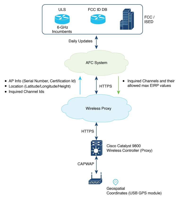
AFC architecture includes these components:
-
Cisco Catalyst APs supporting 6-GHz
-
Cisco Catalyst 9800 Series Wireless Controller acting as AFC proxy
-
A cloud-based wireless proxy tunneling the communication between the AFC proxy and the AFC system
-
AFC System
The 6-GHz AFC workflow operates as follows:
-
A standard power AP joins the system. Before enabling standard power, the AP must get the available frequencies and the power in each frequency range from the AFC system.
-
The AFC proxy sends the AP information to the AFC system.
-
The AFC system computes the available frequencies and maximum allowable power based on the information provided by the regulatory body (FCC for United States).
-
The response is sent back to controller, which may assign a standard power channel to the AP based on the allowed channel list returned by the AFC system.
Supported APs
These Wi-Fi 7 APs support AFC:
|
AP Models/feature difference |
9136I |
9166I |
9163E |
9166D1 |
9164I |
9162I |
9178I |
9176I/9176D1 |
9172I |
9179F |
9171I |
9174I |
9174E |
|---|---|---|---|---|---|---|---|---|---|---|---|---|---|
|
First Supported Release |
17.13.1, 17.12.3 |
17.13.1, 17.12.3 |
17.13.1, 17.12.3 |
17.14.1, 17.12.3 |
17.14.1, 17.12.3 |
17.14.1, 17.12.3 |
17.15.2 |
17.15.2 |
17.15.2b, 17.17.1 |
17.18.1 |
17.18.2 |
17.18.2 |
17.18.2 |
|
6GHz/6E slots in AP |
3 |
2 |
2 |
2 |
2 |
2 |
3 |
2 |
2 |
3 |
1 |
2 |
2 |
|
LPI and SP Support |
LPI, SP |
LPI, SP |
SP only |
LPI, SP |
LPI, SP |
LPI, SP |
LPI, SP |
LPI, SP |
LPI, SP |
LPI, SP |
LPI, SP |
LPI, SP |
SP only |
|
AP Type |
Indoor |
Indoor |
Outdoor |
Indoor |
Indoor |
Indoor |
Indoor |
Indoor |
Indoor |
Indoor/Outdoor |
Indoor |
Indoor |
Indoor |
|
GNSS |
External |
External |
External/Internal |
External |
External |
External |
Internal |
Internal |
External |
Internal |
External |
External |
External |
 Note |
The Cisco Wireless 9178I, 9176I, 9176D1, and 9172I Wi-Fi 7 Access Points are not applicable for 17.16.1 release. |
Feature history for automated frequency coordination
This table provides release and related information for the feature explained in this module.
This feature is also available in all the releases subsequent to the one in which they are introduced in, unless noted otherwise.
|
Release |
Feature |
Feature Information |
|---|---|---|
|
Cisco IOS XE 17.12.3 |
Automated Frequency Coordination |
Automated Frequency Coordination (AFC) is an advanced system for coordinating the allocation and utilization of spectrum for access points (APs) that operate within the 6-GHz band. This feature is supported on the following APs:
|
Prerequisites for Automated Frequency Coordination
These are the prerequisites for Automated Frequency Coordination:
-
Ensure that there is cloud connectivity from the controller to the cloud, with a DNS entry in place. AFC operates through either the management port or data ports.
The AFC request is sent only when the controller is onboarded with cloud. This is automatic for hardware platforms like 9800-80, 9800-40 and 9800-L. For cloud controller, you have to manually enter a one-time password (OTP). See Onboarding the Cloud Controller.
-
Before sending an AFC request, check whether the AFC service can be requested by using the show wireless afc ap command. If command output shows yes or up status for all the parameters of an AP, then request is sent out.
-
Standard APs must register with the AFC system by providing these parameters:
-
Geographic coordinates (latitude and longitude)
-
Antenna height above ground level and tolerance as uncertainty height
-
FCC identification number
-
Manufacturer’s unique serial number
-
Firewall Requirements - Ensure your network firewall allows outbound traffic to:
-
dnaservices.cisco.com on port 443
-
commercial.ocsp.identrust.com on port 80
-
-
Restrictions for Automated Frequency Coordination
These are the restrictions for AFC:
-
AFC is not supported on Embedded Wireless Controller (EWC).
Onboard the cloud controller (GUI)
Onboarding the cloud controller requires the generation of a one-time password (OTP). Controller must register with cloud framework to access any cloud service. The cloud service provides identity management services to the controller and securely authenticates the device.
Note |
These steps apply only to the Cisco Catalyst 9800-CL Wireless Controller for Cloud, and are not applicable to the hardware-based Catalyst 9800 Wireless Controllers. |
Follow these steps to onboard the cloud controller:
Procedure
|
Step 1 |
Go to Cisco DNA portal. |
|
Step 2 |
Click Application/Products. |
|
Step 3 |
Select Region using the drop-down and click Register. |
|
Step 4 |
Click Register. |
|
Step 5 |
Enter the product details such as Host Name/IP, Product Name, and Description. |
|
Step 6 |
Click Register. This generates an OTP. The OTP token is a BASE64 encoded JSON payload. A sample OTP token is given below: Example: |
|
Step 7 |
Copy the OTP. |
|
Step 8 |
Go to the controller console. |
|
Step 9 |
Run cloud otp token import command. |
|
Step 10 |
Paste the OTP copied in Step 7 to the console. |
This completes the onboarding procedure. Wait for a few minutes to complete the process.
Configure DNA services (GUI)
Procedure
|
Step 1 |
Choose Configuration > Services > Cloud Services. |
||
|
Step 2 |
Click DNA Services Configuration tab. The DNA Services Configuration section displays these details:
|
||
|
Step 3 |
In the DNA OTP Configuration section and under Generate OTP, select the link provided to navigate to the Cisco DNA website to generate an OTP. |
||
|
Step 4 |
Enter the generated OTP in the OTP Token field. |
||
|
Step 5 |
Click Submit OTP. |
Configure power mode per RF profile (CLI)
You can allow or disallow standard power mode in configuration per RF profile. However, the operating mode for each RF profile is determined based on the configuration, the capabilities of the AP, and the response from the AFC system regarding channel and transmit power values. If there is no connection with the AFC system or if the received Tx power values are extremely low, the AP might automatically switch from standard-power mode to low-power mode as a fallback.
If the standard power granted by the AFC server is greater than the low power, the radio is switched to standard power mode in the case of mixed-mode APs. If the granted standard power is equal to or greater than the low power, the radio is switched to standard power mode.
Note |
As outdoor APs operate only in standard power mode, the RF profile configuration for the standard power mode is not evaluated. |
Note |
We recommend using standard power indoors for unparalleled speed and coverage. While the client and vendor ecosystem is evolving, the current Cisco standard power technology continues to provide advantages for existing standard power and dual-mode clients. Low-power clients will default to 2.4/5GHz until they are fully upgraded to standard power by the client vendors. |
Procedure
|
Step 1 |
Enter global configuration mode. Example: |
|
Step 2 |
Configure the RF profile and enter RF profile configuration mode. Example:Example: |
|
Step 3 |
Configure standard-power mode for 6 GHz band for APs that are capable of low power (LP) and standard power (SP). Example:APs that support only SP mode are not affected by this setting (SP mode is always enabled). |
|
Step 4 |
Return to privileged EXEC mode. Example: |
Configure power mode per RF profile (GUI)
This task enables standard-power service for dual-power mode APs to operate as standard power APs in the 6 GHz spectrum, allowing access to external AFC service through cloud.
The AP can access the external AFC service through cloud. Based on geographical coordinates and spectrum-inquiry requests from APs, the AFC provides responses on the available frequencies and the maximum permissible power in each frequency range.
Procedure
|
Step 1 |
Go to Configuration > Tags & Profiles > RF/Radio. |
||
|
Step 2 |
Click RF tab. To add a new RF profile, see Configuring an RF Profile (GUI). To modify an existing RF profile, select the required RF profile. |
||
|
Step 3 |
Enable Standard-Power Service to allow dual-power (low power or standard power) mode APs to operate as standard power APs in the 6 GHz spectrum. The AP can access the external AFC service through cloud. Based on geographical coordinates and spectrum-inquiry requests from APs, the AFC provides responses on the available frequencies and the maximum permissible power in each frequency range.
|
||
|
Step 4 |
Click Apply to Device. |
Configure AP parameters (GUI)
AFC requires the longitude, latitude, and height of the AP to determine the geolocation of the AP. Longitude and latitude of the AP will be automatically calculated based on one of the following methods:
-
From an internal or external GPS attached to the AP.
-
From an another AP with GPS (also known as anchor AP) and the distance between the two APs.
Note |
Only a few APs on a floor require the GPS unit. The remaining APs can derive their location from the AP with the GPS unit. You can use bulk AP provisioning to configure multiple AP parameters for multiple APs simultaneously. GUI path is Configure > Wireless > Bulk AP Provisioning. |
Procedure
|
Step 1 |
Go to Configuration > Wireless > Access Points. |
||
|
Step 2 |
In the All Access Points section, select a supported AP. |
||
|
Step 3 |
In the Geolocation tab, enter these details:
|
||
|
Step 4 |
Click Apply to Device. |
Configure AP parameters (CLI)
Procedure
|
Step 1 |
Enable privileged EXEC mode. Example: |
||
|
Step 2 |
Configure the AP Above Ground Level (AGL) height in meters. Example:Example:The value range for height is -100 to 1000 meters. The valid range for height uncertainty is 1 to 100 meters. |
||
|
Step 3 |
(Optional) Configure AP GNSS antenna external cable length, in meters. Example:Example:The value range for cable length is 1 to 100, with a default value of 10.
|
AFC details verification
Use the verification commands to check AFC statistics, channel information, request status, responses, AP geolocation data, and power mode settings for troubleshooting and monitoring AFC functionality on 6 GHz APs.
AFC statistics verification
To see AFC statistics information, use this command:
Device# show wireless afc statistics

Total number of 6GHz APs : 4
Number of APs requiring AFC service : 4
Messages sent to AFC : 229
Successful messages received from AFC : 229
Errored AFC messages : 0
AFC messages pending : 0
Last InquiredChannel message sent:
requestId : 12195125900336565222
AP MAC : 10f9.20fd.54e0
Sent timestamp : 08/09/2023 15:14:20
Last InquiredChannel message received:
requestId : 12195125900336565222
AP MAC : 10f9.20fd.54e0
Received timestamp : 08/09/2023 15:14:21
Minimum response time (ms) : 337
Maximum response time (ms) : 40842
Average response time (ms) : 1315
Health check query : Idle
Health check status : OK
Health check timestamp : 08/09/2023 14:58:50
Number of times health check went down : 0

Health check event history
Timestamp #Times Event State RC Context
---------------------------- -------- ----------------------- ------------------------------ --- ---------------
08/09/2023 14:58:50.348063 53 Response received OK 0
08/09/2023 14:58:48.271529 58 Scheduled 0 Timer: 3600s
08/09/2023 14:58:48.271507 53 Sent 0
08/07/2023 09:33:55.990412 6 Not sent No token 0
AFC channel information
To see information of AFC channels, use this command:
Device# show wireless afc channels 20mhz

802.11 6ghz   :  1  1  1  1  1  1  1  1  1  1  1  1  1  1  1  1  1  1  1  1  1  1  1  1  1
Channel IDs   :  1  1  2  2  2  3  3  4  4  4  5  5  6  6  6  7  7  8  8  8  9  9  0  0  0
(20MHz width) :  1  5  9  3  7  1  5  9  3  7  1  5  9  3  7  1  5  9  3  7  1  5  9  3  7
------------------:+--+--+--+--+--+--+--+--+--+--+--+--+--+--+--+--+--+--+--+--+--+--+--+--+--
AP687D.B45C.08F0 : 36 33 36 36 35 36 36 36 26 27 36 36 36 36 36 36 33 33 36 36 36 36 36 36 36
AP687D.B45C.1824 : 36 33 36 36 35 36 36 36 24 26 27 36 36 36 36 36 33 33 36 36 36 36 36 36 36

! Due to space constraints, the channel IDs (for 2-digit and 3-digit channel IDs)
! are given vertically in the output. The output is also truncated to fit the page width.
AFC request status
To see status of the request sent to AFC, use this command:
Device# show wireless afc request

----------------------------------------------------------------------------------------------------
                                  Last AFC Request Sent to AFC Service:
AP Name               Radio MAC      Request Id           AFC Request Status   Status Timestamp
----------------------------------------------------------------------------------------------------
APCC9C.3EF1.1620      10f9.20fe.36a0 12195125900336565035 Response Received    08/07/2023 13:20:39
AP687D.B45C.17AC      687d.b45f.1af0 12195125900336565037 Response Received    08/07/2023 16:07:01
AP687D.B45C.321B      fc58.9a18.c840 12195125900336566836 Sent                 08/07/2023 17:36:11
AP687D.B45C.321F      fc58.9a18.c850 12195125900336566832 Timeout              08/07/2023 17:36:08
.
.
.
AFC response information
To see AFC response to requests, use this command:
Device# show wireless afc response

------------------------------------------------------------------------------------------------------------
AP Name             Radio MAC        Request Id  Expire Time           Last Rcvd Time       Response Code
------------------------------------------------------------------------------------------------------------
AP687D.B45C.16A4    687d.b45f.0e90   1           11/14/2021 21:56:29   11/14/2021 17:56:29  SUCCESS
AP687D.B45C.17AC    687d.b45f.1af0   2           11/14/2021 21:56:30   11/14/2021 17:56:29  SUCCESS
AP687D.B45C.2276    687d.b45f.3190   3           11/14/2021 21:56:30   11/14/2021 17:56:29  INVALID VALUE

! See the Response Code column.
AFC service request capability
To check whether AFC service request can be sent, use this command:
Device# show wireless afc ap

-----------------------------------------------------------------------------------------------------------------------------------------------------------
AP Name            Radio MAC        AFC         Power Mode  Current         AP       6GHz Radio   RF-Profile   RF-Profile    AFC Country  Location  Height
                                    Status      Capability  Power Mode  Admin State  Admin State  Admin State  tx-power std  allowed      known     known
-----------------------------------------------------------------------------------------------------------------------------------------------------------

APCC9C.3EF1.1620   10f9.20fe.36a0   Inactive    SP/LPi      LPi         Up           Down         Yes          Yes           Yes           Yes       Yes
AP687D.B45C.17AC   687d.b45f.1af0   Active      SP/LPi      SP          Up           Up           Yes          Yes           Yes           Yes       Yes
AP-ARCTIC          fc58.9a18.c890   Inactive    SP/LPi      LPi         Up           Up           Yes          Yes           Yes           Yes        No
AFC geolocation information
To see AFC geolocation information to be used in an AFC Request, use this command:
Device# show wireless afc geolocation

-------------------------------------------------------------------------------------------------------------------------------------------------
AP Name            Radio MAC      Location    Longitude   Latitude     Major-axis Minor-axis Orientation Area-of-uncert Height Height   Uncertainty
                                  Type        (degrees)   (degrees)    (meters)   (meters)   (degrees)   (sq. meters)   Type   (meters) (meters)
-------------------------------------------------------------------------------------------------------------------------------------------------
AP687D.B45C.16A4   687d.b45f.0e90 Lin Polygon -122.400140 37.794910                                      1122           AGL    150      6
                                                            -122.399340 37.795020
                                                            -122.399180 37.794390
                                                            -122.400040 37.794270
AP687D.B45C.17AC   687d.b45f.1af0 Ellipse     -73.977760  40.760168    9          9          5.340000    254            AGL    129      3


! The afc geolocation information given in the output refers to coordinates to be used for future AFC requests.
! They do not represent the coordinates used by past AFC requests; for such info see AFC responses in 'show wireless afc response' command.
.
.
.
AFC geolocation information of a Cisco AP
To see geolocation information of a Cisco AP, use this command:
Device# show ap name AP687D.B45C.17AC afc geolocation

Location type                 : Ellipse
Center ellipse - longitude    : -73.977769
Center ellipse - latitude     : 40.760168
Ellipse major-axis (meters)   : 8
Ellipse minor-axis (meters)   : 8
Ellipse orientation           : 2.5
Height (meters)               : 129
Uncertainty (meters)          : 3
AFC response for an AP service request
To see the response from AFC for a service request from an AP, use this command:
Device# show ap name AP687D.B45C.17AC afc response

AP name                : AP687D.B45C.17AC
AP MAC Address         : 687d.b45f.1af0
Response Code          : SUCCESS
Request ID             : 2
Expire Time            : 11/14/2021 21:56:30
Last Rcvd Time         : 11/14/2021 17:56:29
Global Operating Class : 131
    Channel Cfi / Max Eirp :
        1       / 36.000000
        5       / 33.668693
        9       / 36.000000
        13      / 36.000000
        17      / 35.223532
        21      / 36.000000
        25      / 36.000000
        29      / 36.000000
        33      / 26.664962
        37      / 27.799478
        41      / 36.000000
        45      / 36.000000
        49      / 36.000000
        53      / 36.000000

.
.
.
RF profile details
To see the details of an RF profile, use the following command:
Device# show ap rf-profile name default-rf-profile-6ghz detail

Description                       : default rfprofile for 6GHz radio
RF Profile Name                   : default-rf-profile-6ghz
Band                              : 6 GHz
Transmit Power Threshold v1       : -70 dBm
Min Transmit Power                : -10 dBm
Max Transmit Power                : 30 dBm
Operational Rates
  802.11 6GHZ 6M Rate                 : Mandatory
  802.11 6GHZ 9M Rate                 : Supported
  802.11 6GHZ 12M Rate                : Mandatory
  802.11 6GHZ 18M Rate                : Supported
  802.11 6GHZ 24M Rate                : Mandatory
  802.11 6GHZ 36M Rate                : Supported
  802.11 6GHZ 48M Rate                : Supported
  802.11 6GHZ 54M Rate                : Supported
Max Clients                       : 200
Trap Threshold
  Clients                         : 12 clients
  Interference                    : 10%
  Noise                           : -70 dBm
  Utilization                     : 80%
Multicast Data Rate               : auto
Rx SOP Threshold                  : auto
Load Balancing
  Window                          :  5 clients
  Denial                          :  3 count
Coverage Data
  Data                            : -80 dBm
  Voice                           : -80 dBm
  Minimum Client Level            : 3 clients
  Exception Level                 : 25%
RSSI Settings
  RSSI Low Check                  : Disabled
  RSSI Threshold                  : -127 dbm
DCA Channel List                  :
Unused Channel List               :
PSC Channel List                  :
DCA Bandwidth                     : best
DBS Min Channel Width             : 20 MHz
DBS Max Channel Width             : MAX ALLOWED
DCA Foreign AP Contribution       : Enabled
State                             : Up
  Client utilization threshold  : 5%
  Client Reset count            : 1
Client Network Preference         : default
802.11ax
  OBSS PD                         : Disabled
  Non-SRG OBSS PD Maximum         : -62 dBm
  SRG OBSS PD                     : Disabled
  SRG OBSS PD Minimum             : -82 dBm
  SRG OBSS PD Maximum             : -62 dBm
  Broadcast Probe Response        : Disabled
  FILS Discovery                  : Disabled
  Multi-BSSID Profile Name        : default-multi-bssid-profile
NDP mode                          : Auto
Guard Interval                    : 800ns
PSC Enforcement                   : Disabled
Standard-Power mode               : Allowed
AFC power-mode of a Cisco AP
To see AFC power-mode of a Cisco AP, use the following command:
Device# show ap name AP687D.B45C.17AC dot11 6ghz power-mode

Standard-power mode               : Allowed
802.11 parameter configuration of a Cisco AP
To see the 802.11 parameter configuration of a Cisco AP, use the following command:
Device# show ap name AP687D.B45C.1908 config dot11 6ghz

AP 6GHZ Power Mode                            : Low Power Indoor
Low Power Indoor Capable                      : Yes
Standard Power Capable                        : Yes
AFC event details
To see detailed information about AFC events for a Cisco AP, use the following command:
Device# show ap name AP687D.B45C.1908 afc detail

AFC event history

Timestamp                    Event                       AFC Status     Context
---------------------------- --------------------------- -------------- ----------------------------------------
08/07/2023 16:07:01.244077   AFC_EVT_REQ_RESP_RECEIVED   Active         ReqId 12195125900336565037 Response code: 0; SUCCESS
08/07/2023 16:06:55.491957   AFC_EVT_REQ_SENT            Inactive       ReqId 12195125900336565037 Sent to AFC System
08/07/2023 16:06:51.823938   AFC_EVT_REQ_QUEUED          Inactive       AFC request queued: immediate scheduling
08/07/2023 15:28:54.608117   AFC_EVT_REQ_INACTIVE        Inactive       No location information available; No height information available;
 Feedback