High Availability

Feature History for High Availability

This table provides release and related information for the features explained in this module.

These features are available in all the releases subsequent to the one they were introduced in, unless noted otherwise.

Table 1. Feature History for High Availability

Release

Feature

Feature Information

Cisco IOS XE 17.18.1

Enhanced Gateway Reachability Statistics

Improves visibility into gateway reachability and provides detailed statistics for ICMP, ARP, and ND probes. This feature enables simplified troubleshooting, greater transparency, and more reliable diagnostics for HA and RMI functionality.

The following command is introduced:

  • show platform software rif-mgr chassis { active | standby} r0 gateway-statistics

The following command is modified:

  • show platform software rif-mgr chassis { active | standby} r0 resource-status

Cisco IOS XE Cupertino 17.9.1

High Availability Deployment for Application Centric Infrastructure (ACI) Network

This feature avoids interleaving traffic between the old and new active controller using the following functionalities:

  • Bringing down Wireless Management Interface (WMI) faster.

  • Disabling fast switchover notification.

Link Layer Discovery Protocol (LLDP) Support in the Standby Controller

From this release, the Link Layer Discovery Protocol (LLDP) process will be up and running in both active and standby controllers.

Cisco IOS XE Bengaluru 17.6.1

Standby Interface Status using Active SNMP

This feature allows the standby controller interface status to be queried at the active using SNMP.

Cisco IOS XE Bengaluru 17.5.1

Auto-Upgrade

The auto-upgrade feature enables the standby controller to upgrade to active controller's software image, so that both controllers can form an high availability (HA) pair.

Cisco IOS XE Bengaluru 17.5.1

Standby Monitoring Enhancements

The Standby Monitoring Enhancements feature monitors the standby CPU or memory information from the active controller. Also, this feature independently monitors the standby controller using SNMP for the interface MIB.

The cLHaPeerHotStandbyEvent and cLHaPeerHotStandbyEvent MIB objects in CISCO-HA-MIB are used to monitor the standby HA status.

Cisco IOS XE Bengaluru 17.4.1

Gateway Reachability Detection

Gateway reachability feature minimizes the downtime on APs and clients when the gateway reachability is lost on the active controller.

Cisco IOS XE Amsterdam 17.1.1s

Redundant Management Interface

The Redundancy Management Interface (RMI) is used as a secondary link between the active and standby controllers. This interface is the same as the Wireless Management Interface and the IP address on this interface is configured in the same subnet as the Wireless Management Interface.

Information About High Availability

High Availability (HA) allows you to reduce the downtime of wireless networks that occurs due to the failover of controllers. The HA Stateful Switch Over (SSO) capability on the controller allows AP to establish a CAPWAP tunnel with the active controller. The active controller shares a mirror copy of the AP and client database with the standby controller. The APs won’t go into the discovery state and clients don’t disconnect when the active controller fails. The standby controller takes over the network as the active controller. Only one CAPWAP tunnel is maintained between the APs and the controller that is in an active state.

HA supports full AP and client SSO. Client SSO is supported only for clients that have completed the authentication and DHCP phase, and have started passing traffic. With Client SSO, the client information is synced to the standby controller when the client associates to the controller or when the client parameters change. Fully authenticated clients, for example, the ones in RUN state, are synced to the standby. Thus, client reassociation is avoided on switchover making the failover seamless for the APs and clients, resulting in zero client service downtime and zero SSID outage. This feature reduces major downtime in wireless networks due to failure conditions such as box failover, network failover, or power outage on the primary site.


Note


  • In HA mode, the RP port shut or no shut should not be performed during the controller bootup.

  • If the RP communication is lost between active and standby controller during HA sync, the standby controller crashes as the IPC communication fails. The crash is intentional.

    If RP link is restored, the standby controller gracefully reloads and forms an HA pair.


Note


When the controller works as a host for spanning tree, ensure that you configure portfast trunk, using spanning-tree port type edge trunk or spanning-tree portfast trunk commands, in the uplink switch to ensure faster convergence.


Note


You can configure FIPS in HA setup. For information, see the Configuring FIPS in HA Setup.


Note


The IPv4 secondary address is used internally for RMI purpose. So, it is not recommended to configure the secondary IPv4 address.

In case of IPv6, only one management IPv6 is allowed, secondary address is configured for RMI-IPv6 purpose. It is not recommended to have more than one IPv6 management on the Wireless Management Interface (WMI).

More than one management IPv4 and IPv6 addresses on WMI can result in unpredictable behavior.


Prerequisites for High Availability

External Interfaces and IPs

Because all the interfaces are configured only on the Active box, but are synchronized with the Standby box, the same set of interfaces are configured on both controllers. From external nodes, the interfaces connect to the same IP addresses, irrespective of the controllers they are connected to.

For this purpose, the APs, clients, DHCP, Cisco Prime Infrastructure, Cisco Catalyst Centre, and Cisco Identity Services Engine (ISE) servers, and other controller members in the mobility group always connect to the same IP address. The SSO switchover is transparent to them. But if there are TCP connections from external nodes to the controller, the TCP connections need to be reset and reestablished.

HA Interfaces

The HA interface serves the following purposes:

  • Provides connectivity between the controller pair before an IOSd comes up.

  • Provides IPC transport across the controller pair.

  • Enables redundancy across control messages exchanged between the controller pair. The control messages can be HA role resolution, keepalives, notifications, HA statistics, and so on.

You can select either SFP or RJ-45 connection for HA port. Supported Cisco SFPs are:

  • GLC-SX-MMD

  • GLC-LH-SMD


Note


It is recommended to connect either the SFP port or the RJ-45 port to the peer, but not both ports simultaneously.


When either SFP or RJ-45 connection is present, HA works between the two controllers. If SFP is connected when RJ-45 HA is up and running, the HA pair reloads. The reload occurs even if the link between the SFPs isn’t connected.


Note


  • It is recommended to have a dedicated physical NIC and Switch for RP when the HA pair is deployed across two host machines. This avoids any keep-alive loses and false HA switchovers or alarms.

  • Disable security scans on VMware virtual instances.


Note


Connect RPs via switches to enable controller HA. Ensure that the round-trip time between the two controllers is less than 80 milliseconds.


Restrictions on High Availability

  • For a fail-safe SSO, wait till you receive the switchover event after completing configuration synchronization on the standby controller. If the standby controller has just been booted up, we recommend that you wait x minutes before the controller can handle switchover events without any problem. The value of x can change based on the platform. For example, a Cisco 9800-80 Series Controller running to its maximum capacity can take up to 24 minutes to complete the configuration synchronization before being ready for SSO. You can use the show wireless stats redundancy config database command to view the database-related statistics.

  • The flow states of the NBAR engine are lost during a switchover in an HA scenario in local mode. Because of this, the classification of flows will restart, leading to incorrect packet classification as the first packet of the flow is missed.

  • The HA connection supports only IPv4.

  • Switchover and an active reload and forces a high availability link down from the new primary.

  • Hyper threading is not supported and if enabled HA keepalives will be lost in case of an HA system that results in stack merge.

  • Standby RMI interface does not support Web UI access.

  • Two HA interfaces (RMI and RP) must be configured on the same subnet, and the subnet cannot be shared with any other interfaces on the device.

  • It is not possible to synchronize a TCP session state because a TCP session cannot survive after a switchover, and needs to be reestablished.

  • The Client SSO does not address clients that have not reached the RUN state because they are removed after a switchover.

  • Statistics tables are not synced from active to standby controller.

  • Machine snapshot of a VM hosting controller HA interfaces is not supported. It may lead to a crash in the HA controller.

  • Mobility-side restriction: Clients which are not in RUN state will be forcefully reauthenticated after switchover.

  • The following application classification may not be retained after the SSO:

    • AVC limitation—After a switchover, the context transfer or synchronization to the Standby box does not occur and the new active flow needs to be relearned. The AVC QoS does not take effect during classification failure.

    • A voice call cannot be recognized after a switchover because a voice policy is based on RTP or RTCP protocol.

    • Auto QoS is not effective because of AVC limitation.

  • The active controller and the standby controller must be paired with the same interface for virtual platforms. For hardware appliance, there is a dedicated HA port.

  • Static IP addressing can synch to standby, but the IP address cannot be used from the standby controller.

  • You can map a dedicated HA port to a 1 GB interface only.

  • To use EtherChannels in HA mode in releases until, and including, Cisco IOS XE Gibraltar 16.12.x, ensure that the channel mode is set to On.

  • EtherChannel Auto-mode is not supported in HA mode in releases until, and including, Cisco IOS XE Gibraltar 16.12.x.

  • LACP and PAGP is not supported in HA mode in releases until, and including, Cisco IOS XE Gibraltar 16.12.x.

  • When the controller works as a host for spanning tree, ensure that you configure portfast trunk in the uplink switch using spanning-tree port type edge trunk or spanning-tree portfast trunk command to ensure faster convergence.

  • The clear chassis redundancy and write erase commands will not reset the chassis priority to the default value.

  • While configuring devices in HA, the members must not have wireless trustpoint with the same name and different keys. In such a scenario, if you form an HA pair between the two standalone controllers, the wireless trustpoint does not come up after a subsequent SSO. The reason being the rsa keypair file exists but it is incorrect as the nvram:private-config file is not synched with the actual WLC_WLC_TP key pair.

    As a best practice, before forming an HA, it is recommended to delete the existing certificates and keys in each of the controllers which were previously deployed as standalone.

  • After a switchover, when the recovery is in progress, do not configure the WLAN or WLAN policy. In case you configure, the controller can crash.

  • After a switchover, clients that are not in RUN state and not connected to an AP are deleted after 300 seconds.

Guidelines for RP Port Configuration

The following are guidelines for RP port configuration:

  • The IP addresses for Local and Remote IP must be in the same subnet.

  • Use the 169.254.X.X/16 subnet; derive the last two octets from the management interface.

  • Avoid using 10.10.10.x/24 subnet for the RP port.

  • For more information about RMI+RP chosen as the redundancy method, see Information About Redundancy Management Interface.

Configuring High Availability (CLI)

Before you begin

The active and standby controller should be in the same mode, either Install mode or Bundle mode, with same image version. We recommend that you use Install mode.

Procedure

  Command or Action Purpose

Step 1

chassis chassis-num priority chassis-priority

Example:

Device# chassis 1 priority 1

(Optional) Configures the priority of the specified device.

Note


From Cisco IOS XE Gibraltar 16.12.x onwards, device reload is not required for the chassis priority to become effective.

  • chassis-num —Enter the chassis number. The range is from 1 to 2.

  • chassis-priority —Enter the chassis priority. The range is from 1 to 2. The default value is 1.

Note


When both the devices boot up at the same time, the device with higher priority(2) becomes active, and the other one becomes standby. If both the devices are configured with the same priority value, the one with the smaller MAC address acts as active and its peer acts as standby.

Step 2

chassis redundancy ha-interface GigabitEthernet numlocal-ip local-chassis-ip-addr network-mask remote-ip remote-chassis-ip-addr

Example:

Device# chassis redundancy ha-interface 
GigabitEthernet 2 local-ip 4.4.4.1 /24 remote-ip 4.4.4.2

Configures the chassis high availability parameters.

  • num —GigabitEthernet interface number. The range is from 0 to 32.

  • local-chassis-ip-addr —Enter the IP address of the local chassis HA interface.

  • network-mask —Enter the network mask or prefix length in the /nn or A.B.C.D format.

  • remote-chassis-ip-addr —Enter the remote chassis IP address.

Step 3

chassis redundancy keep-alive timer timer

Example:

Device# chassis redundancy keep-alive timer 6 

Configures the peer keepalive timeout value.

Time interval is set in multiple of 100 ms (enter 1 for default).

Step 4

chassis redundancy keep-alive retries retry-value

Example:

Device# chassis redundancy keep-alive retries 8

Configures the peer keepalive retry value before claiming peer is down. Default value is 5.

Disabling High Availability

If the controller is configured using RP method of SSO configuration, use the following command to clear all the HA-related parameters, such as local IP, remote IP, HA interface, mask, timeout, and priority:

clear chassis redundancy


Note


This command is not supported on these models:

  • Cisco Catalyst CW9800H1 Wireless Controller.

  • Cisco Catalyst CW9800H2 Wireless Controller.

  • Cisco Catalyst CW9800M Wireless Controller.

    RMI-based High Availability is mandatory in the Cisco Catalyst CW9800H1 Wireless Controller, Cisco Catalyst CW9800H2 Wireless Controller and Cisco Catalyst CW9800M Wireless Controller.


If the controller is configured using RMI method, use the following command:

no redun-management interface vlan chassis


Note


Reload the devices for the changes to take effect.


After the HA unpairing, the standby controller startup configuration and the HA configuration will be cleared and standby will go to Day 0.

Before the command is executed, the user is prompted with the following warning on the active controller:


Device# clear chassis redundancy

WARNING: Clearing the chassis HA configuration will result in both the chassis move into
Stand Alone mode. This involves reloading the standby chassis after clearing its HA
configuration and startup configuration which results in standby chassis coming up as a totally
clean after reboot. Do you wish to continue? [y/n]? [yes]:

*Apr 3 23:42:22.985: received clear chassis.. ha_supported:1yes
WLC#
*Apr 3 23:42:25.042: clearing peer startup config
*Apr 3 23:42:25.042: chkpt send: sent msg type 2 to peer..
*Apr 3 23:42:25.043: chkpt send: sent msg type 1 to peer..
*Apr 3 23:42:25.043: Clearing HA configurations
*Apr 3 23:42:26.183: Successfully sent Set chassis mode msg for chassis 1.chasfs file updated
*Apr 3 23:42:26.359: %IOSXE_REDUNDANCY-6-PEER_LOST: Active detected chassis 2 is no
longer standby

On the standby controller, the following messages indicate that the configuration is being cleared:

Device-stby#

*Apr 3 23:40:40.537: mcprp_handle_spa_oir_tsm_event: subslot 0/0 event=2
*Apr 3 23:40:40.537: spa_oir_tsm subslot 0/0 TSM: during state ready, got event 3(ready)
*Apr 3 23:40:40.537: @@@ spa_oir_tsm subslot 0/0 TSM: ready -> ready
*Apr 3 23:42:25.041: Removing the startup config file on standby

!Standby controller is reloaded after clearing the chassis.

Copy a WebAuth tar bundle to the standby controller

Use the following procedure to copy a WebAuth tar bundle to the standby controller, in a high-availability configuration.

Follow this procedure to copy the tar bundle to the standby controller.

Procedure


Step 1

Choose Choose Administration > Management > Backup & Restore.

Step 2

From the Copy drop-down list, choose To Device.

Step 3

From the File Type drop-down list, choose WebAuth Bundle.

Step 4

From the Transfer Mode drop-down list, choose TFTP, SFTP, FTP, or HTTP.

The Server IP Address and File Path fields vary with the transfer mode.

  • TFTP

    • IP Address (IPv4/IPv6): Enter the server IP address (IPv4 or IPv6) of the TFTP server you want to use.

    • File Path: Enter the file path. Start the file path with a slash (/path).

    • File Name: Enter a file name.

      The file name should not contain spaces. Use underscores (_) and hyphens (-). Ensure the file name ends with .tar, e.g., webauthbundle.tar.

  • SFTP

    • IP Address (IPv4/IPv6): Enter the server IP address (IPv4 or IPv6) of the SFTP server that you want to use.

    • File Path: Enter the file path. Start the file path with a slash (/path).

    • File Name: Enter a file name.

      The file name should not contain spaces. Underscores (_) and hyphen (-) are the only special characters that are supported. Ensure that file name ends with .tar, for example, webauthbundle.tar.

    • Server Login UserName: Enter the SFTP server login user name.

    • Server Login Password: Enter the SFTP server login passphrase.

  • FTP

    • IP Address (IPv4/IPv6): Enter the server IP address (IPv4 or IPv6) of the TFTP server that you want to use.

    • File Path: Enter the file path. Start the file path with a slash (/path).

    • File Name: Enter a file name.

      The file name should not contain spaces. Underscores (_) and hyphen (-) are the only special characters that are supported. Ensure that file name ends with .tar, for example, webauthbundle.tar.

    • Logon Type: Choose the login type as either Anonymous or Authenticated. If you choose Authenticated, the following fields are activated:

      • Server Login UserName: Enter the FTP server login user name.

      • Server Login Password: Enter the FTP server login passphrase.

  • HTTP

    • Source File Path: Click Select File to select the configuration file, and click Open.

Step 5

Click the Yes or No radio button to back up the existing startup configuration to Flash.

Save the configuration to Flash to propagate the WebAuth bundle to other members, including the standby controller. If you do not save the configuration to Flash, the WebAuth bundle will not be propagated to other members, including the standby controller.

Step 6

Click Download File.


System and Network Fault Handling After 17.5

If the standby controller crashes, it reboots and comes up as the standby controller. Bulk sync follows causing the standby to become hot. If the active controller crashes, the standby becomes active. The new active controller assumes the role of primary and tries to detect a dual active.

The following matrices provide a clear picture of the conditions the controller switchover would trigger:

Table 2. System and Network Fault Handling after 17.5

Number

RP Link

Reachability Through RMI

GW From Active

GW From Standby

SSO

Result

Additional Information

1

Up

P-Reachable

G-Reachable

G-Reachable

No SSO

No Action

2

Up

P-Reachable

G-Reachable

G-Unreachable

No SSO

No action is required. The standby unit is not ready for SSO in this state because it does not have gateway reachability. In this scenario, the standby unit appears in standby-recovery mode.

Spring Back:

If the gateway reachability is restored (G_Reachable), the controller returns to Standby state (no reboot is necessary).

Note


RP resources and gateway resources each trigger distinct actions.

Spring Back: If the gateway reachability is restored (G_Reachable), the controller transitions to Standby state. A reboot is not required.

3

Up

P-Reachable

G-Unreachable

G-Reachable

SSO

The system exchanges gateway reachability messages over the RMI and RP links. When the active controller reboots, the standby controller takes over as the active controller. The RP goes down during the reboot process.

The Stack Manager sends a message to the standby controller to initiate a role change. The standby controller consults the active controller.

  • If the active controller responds, the standby controller determines that the active controller does not have all the required resources and allows the role change.

  • If the active controller does not respond, or if the RMI link is down, the standby controller proceeds with the role change because it has all the resources required to become active.

4

Up

P-Reachable

G-Unreachable

G-Unreachable

No SSO

The standby controller is not ready for SSO in this state because it does not have gateway reachability. The standby controller appears in Standby-Recovery mode.

SpringBack:

If the gateway reachability is restored on the Standby-Recovery controller (G_Reachable), the controller transitions to the standby state.

5

Up

P-Unreachable

G-Reachable

G-Reachable

No SSO

No action taken when RMI goes DOWN. There will be no DAD when the RMI link is DOWN.

If gateway reachability (G_Reachable) is lost, the controller transitions to Standby. This situation is managed as case (3)

The active controller maintains its state when gateway reachability is lost.

No action is taken when the RMI link goes down.

Dual-Active Detection (DAD) does not occur when the RMI link is down.

6

Up

P-Unreachable

G-Reachable

G-Unreachable

No SSO

No Action. Standby is not ready for SSO in this state as it does not have gateway reachability. The standby shall be shown to be in standby-recovery mode.

Spring Back:

If the gateway reachability is restored (G_Reachable), the controller shall go to Standby mode without a reload.

There shall be no action if the RMI comes UP.

7

Up

P-Unreachable

G-Unreachable

G-Reachable

SSO

A gateway reachability message is also exchanged over the RP link. The Active device reboots so that the Standby device becomes the new Active. The RP link goes down when the Active device reboots. The Stack Manager sends a message over the RP and RMI links to the Standby Controller to initiate the role change. The Standby controller consults the Active device.

  • . If the Active responds, the Standby determines that the Active does not have all resources and allows the role change.

  • If the Active does not respond—possibly because the RP link is already down—the Standby allows the role change regardless of resource status.

When the active controller reboots, the RP goes down. The Stack Manager sends a message over the RP and RMI link to the standby controller to initiate a role change. The standby controller consults the active controller.

8

Up

P-Unreachable

G-Unreachable

G-Unreachable

No SSO

The standby controller is not ready for SSO in this state because it does not have gateway reachability. The standby controller appears in standby-recovery mode.

Spring Back:

If gateway reachability is restored on the standby-recovery controller (G_Reachable), the controller transitions to standby. Refer to step 7 for more details.

The active controller does not change its state when gateway reachability is lost.

No action occurs if the RMI comes up.

When the Active device reboots, the RP goes down. The Stack Manager sends a message over the RP and RMI links to the Standby Controller to initiate a role change.

The Standby Controller consults the Active Controller.

  • . If the Active responds, the Standby deduces that the Active does not have all the required resources and proceeds with the role change.

  • If the Active does not respond (for example, if the RP is already down), the Standby allows the role change regardless of the resource status.

9

Down

P-Reachable

G-Reachable

G-Reachable

No SSO

When the RP is not available, the standby transitions to Standby-Recovery mode. The stack manager requests a role change when the RP goes down. If the RMI is up, the RIF manager sends a message to the active unit to check its status. If a response is received, the standby does not allow the role change and transitions to Standby-Recovery. If there is no response, such as when the active unit is down due to a crash, the role change is allowed.

This scenario works differently if the RP goes down before the standby reaches Standby-Hot state. If the RP link goes down before the standby becomes Standby-Hot, the RIF sends a positive response to the stack manager, resulting in a controller reload.

Spring Back:

If gateway reachability is restored on the Standby-Recovery (G_Reachable), the controller transitions to Standby. In this case, refer to state (7). The Active controller does not change its state when gateway reachability is lost. No action is taken if the RMI comes up.

10

Down

P-Reachable

G-Reachable

G-Unreachable

No SSO

The standby is not ready for SSO in this state because it does not have gateway reachability. The standby will appear in standby-recovery mode.

There are two possible scenarios:

  • The RP goes down first, followed by the standby gateway.

  • The standby gateway goes down first, followed by the RP.

Consider the case where the RP goes down first. In this situation, the stack manager requests a role change. However, because the standby does not have gateway reachability, it cannot allow the role change. The system starts a 30-minute timer when the RMI goes down (meaning both the RP and RMI are down).

If the RP goes down before the standby is in standby-hot state, the system reloads. There are several sub-cases:

  • If the active unit crashes and returns within 30 minutes, the timer stops. The standby remains in recovery and reboots when the RP is up.

  • If the RP stays down, no action is taken when the timer expires, provided the RMI is up.

  • If the active unit continuously crashes, the timer expires with the RMI down, and the standby-recovery unit reboots as the active unit.

Spring Back:

  • If the gateway returns first, the standby-recovery unit remains in recovery.

  • If the RP returns first, the system reboots to standby-recovery or standby, depending on whether the gateway is reachable.

When the RP goes down, the stack manager requests a role change. While the RMI is operational, the RIF manager sends a message to the active controller to verify its status. If a response is received, the standby controller prevents the role change and transitions to standby-recovery. If there is no response, such as when the active controller is down due to a crash, the role change is permitted.

However, if the RP goes down before the standby controller reaches the standby-hot state, the RIF manager sends a positive response to the stack manager, which results in a controller reload.

11

Down

P-Reachable

G-Unreachable

G-Reachable

SSO

The system exchanges gateway reachability messages over RP and RMI links.

When the Old-Active controller transitions to Active-Recovery mode, configuration mode is disabled. All interfaces are set to ADMIN DOWN, except for the wireless management interface with the RMI IP address.

When the RP link comes up, the controller in Active-Recovery reloads to become standby. If the gateway remains unreachable, it reloads to become standby-recovery.

If the gateway (GW) is lost and the RP link goes down less than eight seconds after the gateway loss, the following actions occur. The stack manager requests a role change on the standby controller. If the standby controller has not reached Standby-Hot state, it allows a reload. Otherwise, it queries the active controller.

If the active controller lacks resources and responds affirmatively, the standby controller becomes active, DAD runs, and the old active controller transitions to Active-Recovery.

Assume that the active device has already lost the gateway (GW), and then the RP goes down. If the gateway is lost for less than eight seconds, the system triggers a stateful switchover (SSO) that is initiated by the gateway. This scenario describes when the gateway has been lost for less than eight seconds before the RP goes down.

In this case, the Stack Manager requests a role change from the standby device. If the standby has not yet reached the Standby-Hot state, the system sends a positive response to the Stack Manager. Since the standby has all resources available except for the RP, it sends a query to the active device to request a role change. The active device responds affirmatively because it does not have all the necessary resources.

The standby then becomes active. DAD must run to ensure that the new active device maintains its status. The former active device enters the Active-Recovery state.

Spring Back:

The controller in Active-Recovery reboots after the RP link is restored. If the gateway is still down, the controller transitions to standby-recovery. If the gateway is restored, the controller transitions to standby.

12

Down

P-Reachable

G-Unreachable

G-Unreachable

No SSO

p

Standby transitions to Standby-Recovery. Assume both controllers lose gateway, then RP goes down. Stack manager requests a role change. Because Standby lacks resources, it starts a 30-minute timer when RMI goes down (that is, RP and RMI are both down).

here are three possible outcomes:

  • If Active recovers within 30 minutes, the timer stops. Standby remains in recovery and may reboot when RP returns.

  • If RP stays down, no action occurs when the timer expires, provided RMI is up.

  • If Active never recovers, the timer expires with RMI down, and Standby-Recovery reboots as Active.

  • If Active never recovers, the timer expires with RMI down, and Standby-Recovery reboots as Active.

Note


If gateway reachability was not enabled, SSO is not allowed when Active is up. If Active is down and Standby is standby-hot, SSO is allowed. If RP returns before standby-hot, it reloads. Note: Recovery to Standby without reload is possible only if recovery was due solely to gateway.

Spring Back:

  • If gateway returns first, the system remains in Standby-Recovery.

  • If RP returns first, the system reboots to Standby-Recovery and then to Standby if gateway is up.

Let us assume that both the controllers lost their GW and then the RP went DOWN.

The stack manager will request for a role change when the RP goes DOWN. The standby anyway does not have all resources (Gateway Reachability at present) and hence it shall not allow role change to happen. It will start the 30 min timer when RMI goes DOWN( timer starts when RP+RMI are DOWN).There are now two possibilities:

  • The active suffered a software glitch (For example: a crash) in which case, it would come up within 30 minutes and the timer would be stopped. The standby will continue to be in standby-recovery. If the RP comes UP when the timer is running, the Standby-Recovery would reboot and might come up as Standby or Standby-Recovery.

  • Physical RP connection went down and it remains down. When the timer expires, if the RMI is UP, no action shall be taken.

  • The active continuously crashes, that is, it does not come up after 30 minutes. In this case, when the timer expires,the RMI will be DOWN. The standby-recovery shall reboot when the timer expires (and might come UP as Active.)

When RP DOWN event is received, if the Gateway Reachability is not enabled, Gateway will not be considered as a resource. In this case, SSO shall not be allowed if the Active is UP. SSO shall be allowed if Active is DOWN, provided Standby is in Standby-Hot state.

If the RP link goes down before the standby becomes standby-hot, it shall reload.

Note


The Standby-Recovery that has lost RP is no more Standby Hot. This implies that the recovery from Standby-Recovery to Standby without a reboot (as was the case earlier in 17.2) is not possible for RP events. It is however possible for Gateway events.

Spring Back:

  • When the Standby-Recovery findsGateway is UP it continues to be in Standby-Recovery if RP is still DOWN.

  • When the Standby-Recovery finds that its RP is UP, it will reboot and come up as Standby-Recovery

13

Down

P-Unreachable

G-Reachable

G-Reachable

SSO

A double fault may result in two active controllers. When this occurs, the Standby controller becomes active, but the original Active controller may still exist. Once connectivity is restored, role negotiation ensures that the most recent Active controller is retained.

In the event that RMI goes down and then RP also goes down, the stack manager requests a role change. If RMI is unavailable, Standby grants the role change only if it is in standby-hot mode; otherwise, it denies the request. If RP returns before standby-hot mode is reached, it reloads.

Spring Back:

If RMI returns, the previous Active controller enters Active-Recovery mode. When RP returns, the controller reboots and transitions to Standby. If RP goes down, RMI goes down, and the timer expires, Standby reboots as Active. The timer may be skipped in cases of a pure double fault.

Note

 
You may skip the timer for pure double-fault cases.

Let us assume that the RMI goes DOWN first and then the RP goes DOWN. When the RP goes DOWN, the stack manager requests a role change. Since the RMI is DOWN, the standby cannot consult with the Active. The standby allows a role change to become Active, regardless of its resource state, provided the standby is in Standby-Hot. If the standby is not in Standby-Hot, a role change is not allowed. If the RP link goes down before the standby becomes Standby-Hot, the standby reloads

Spring Back:

If the RMI comes UP at any time, Old Active transitions to Active-Recovery. Active-Recovery reboots when the RP comes up, after which it will become Standby.

If the RP goes DOWN first, refer to case (9). If RP_DOWN and RMI_DOWN occur in that sequence and the 30-minute timer expires, the standby shall reboot. It will come up as Active if RP and RMI continue to be DOWN. Alternatively, the 30-minute timer may not be started in this case.

What if the RP goes DOWN first - see case(9) above.

If the RP goes DOWN first, refer to case (9). If RP_DOWN and RMI_DOWN occur in that sequence and the 30-minute timer expires, the standby shall reboot. It will come up as Active if RP and RMI continue to be DOWN. Alternatively, the 30-minute timer may not be started in this case.

The timer can be used when the standby does not have all required resources, such as gateway reachability at present or port status and gateway reachability in the future, to take over as Active.

Note


Another option is to not start the 30-minute timer in this situation. Use the timer only if the standby does not have all the required resources to take over as active. Currently, this refers to gateway reachability; in the future, it may also include port status and gateway reachability.

14

Down

P-Unreachable

G-Reachable

G-Unreachable

No SSO

Double fault – two active controllers possible. Old Active stays Active; Standby may become Active if connectivity is not restored within a set time. If Standby is in standby-recovery due to GW loss, then RMI goes down, then RP goes down. Stack manager requests role change; no RMI means no consult, so Standby allows change. If Active crashed, it restarts as Standby; if both come up, split-brain conflict may occur.

Let us assume that the Standby is inStandby-Recovery mode as it loses GW.

Let us assume that the RMI goes DOWN first and then the RP goes DOWN.

The stack manager shall request role change when the RP goes DOWN. Since the RMI isDOWN, the standby cannot consult with the Active. The standby shall allow role change.

Spring Back:

If RMI returns, Old Active enters Active-Recovery and reboots on RP return to become Standby

15

Down

P-Unreachable

G-Unreachable

G-Reachable

SSO

Double fault – two active controllers possible. Standby becomes active; old Active may still exist. Role negotiation occurs once connectivity is restored. Assume GW loss on Active, then RMI down then RP down. Stack manager requests role change; no RMI means standby allows change if in standby-hot, else reloads. If RP returns before standby-hot, it reloads.

Spring Back:

If RMI returns, old Active goes to Active-Recovery and reboots on RP return to become Standby.

Suppose the Standby is in Standby-Recovery mode after losing GW. Assume the RMI goes down first, then the RP goes down. The stack manager requests a role change when the RP goes down. Because the RMI is down, the Standby cannot consult with the Active, so it allows the role change. If the Active went down due to a software glitch, it will come up and become Standby. If no communication is established between the two controllers, both may become active, causing a network conflict

Spring Back:

If the RMI comes UP at some point of time,Old Active will go to Active-Recovery. Active-Recovery shall reboot when the RP comes up and will become Standby.

16

Down

P-Unreachable

G-Unreachable

G-Unreachable

No SSO

A double fault can result in two active controllers. The old Active remains Active, and the Standby may become Active if connectivity is not restored within a stipulated time.

If both controllers lose GW and the Standby is in standby-recovery, then RMI goes down, followed by RP going down. The stack manager requests a role change. If there is no RMI, the Standby allows the change, which can cause a conflict.

Spring Back:

If RMI returns, the old Active enters Active-Recovery and, when RP returns, reboots to become Standby.

Assume that both Active and Standby lose GW, and Standby enters Standby-Recovery. If RMI goes DOWN first, followed by RP going DOWN, the stack manager requests a role change when RP goes DOWN. Since RMI is DOWN, Standby cannot consult with Active and allows the role change. This situation can cause a network conflict.

Spring Back:

If RMI comes UP at any point, the old Active transitions to Active-Recovery. Active-Recovery reboots when RP comes UP and then becomes Standby.

Handling Recovery Mechanism

Active to Active Recovery

  • When RP is down and RMI is up at boot up, the Active Recovery occurs.

  • When HA is stable (active - standby), if RMI is down first and then RP goes down next, and later if RMI comes up before RP comes up, the Active to Active Recovery occurs. Once the RP is up, the Active Recovery reloads and HA is formed.

Standby to Standby Recovery

  • If Gateway goes down, standby goes to standby-recovery mode. Standby means, its state is up to date with the active. But since it does not have the other resource (Gateway) it goes to Standby-Recovery. If standby is in the hot state, then it is in a position to take over the active functionality. Standby-Recovery will go back to Standby without a reload, once it detects that the Gateway reachability is restored.

  • When Standby goes to Standby Recovery for Gateway alone, once the Gateway is up, the HA comes up without any reboot.

  • When Standby goes to Standby Recovery for RP down, once the RP is up, the standby recovery reboots automatically and HA is formed.

Verifying High Availability Configurations

To view the HA configuration details, use the following command:

Device# show romvar
ROMMON variables:
 LICENSE_BOOT_LEVEL =
 MCP_STARTUP_TRACEFLAGS = 00000000:00000000
 BOOTLDR =
 CRASHINFO = bootflash:crashinfo_RP_00_00_20180202-034353-UTC
 STACK_1_1 = 0_0
 CONFIG_FILE =
 BOOT = bootflash:boot_image_test,1;bootflash:boot_image_good,1;bootflash:rp_super_universalk9.vwlc.bin,1;
 RET_2_RTS =
 SWITCH_NUMBER = 1
 CHASSIS_HA_REMOTE_IP = 10.0.1.9
 CHASSIS_HA_LOCAL_IP = 10.0.1.10
 CHASSIS_HA_LOCAL_MASK = 255.255.255.0
 CHASSIS_HA_IFNAME = GigabitEthernet2
 CHASSIS_HA_IFMAC = 00:0C:29:C9:12:0B
 RET_2_RCALTS =
 BSI = 0
 RANDOM_NUM = 647419395

Verifying AP or Client SSO Statistics

To view the AP SSO statistics, use the following command:

Device# show wireless stat redundancy statistics ap-recovery wnc all
AP SSO Statistics                                                     

Inst    Timestamp     Dura(ms)   #APs  #Succ  #Fail  Avg(ms)  Min(ms)  Max(ms)
------------------------------------------------------------------------------
   0    00:06:29.042        98     34     34      0        2        1       35
   1    00:06:29.057        56     33     30      3        1        1       15
   2    00:06:29.070        82     33     33      0        2        1       13


Statistics:

WNCD Instance   : 0
No. of AP radio recovery failures          : 0
No. of AP BSSID recovery failures          : 0
No. of CAPWAP recovery failures            : 0
No. of DTLS recovery failures              : 0
No. of reconcile message send failed       : 0
No. of reconcile message successfully sent : 34
No. of Mesh BSSID recovery failures: 0
No. of Partial delete cleanup done : 0
.
.
.

To view the Client SSO statistics, use the following command:

Device# show wireless stat redundancy client-recovery wncd all
Client SSO statistics                                                      
----------------------                                                     

WNCD instance  : 1
Reconcile messages received from AP                     : 1
Reconcile clients received from AP                      : 1
Recreate attempted post switchover                      : 1
Recreate attempted by SANET Lib                         : 0
Recreate attempted by DOT1x Lib                         : 0
Recreate attempted by SISF Lib                          : 0
Recreate attempted by SVC CO Lib                        : 1
Recreate attempted by Unknown Lib                       : 0
Recreate succeeded post switchover                      : 1
Recreate Failed post switchover                         : 0
Stale client entries purged post switchover             : 0

Partial delete during heap recreate                     : 0
Partial delete during force purge                       : 0
Partial delete post restart                             : 0
Partial delete due to AP recovery failure               : 0
Partial delete during reconcilation                     : 0

Client entries in shadow list during SSO                : 0
Client entries in shadow default state during SSO       : 0
Client entries in poison list during SSO                : 0

Invalid bssid during heap recreate                      : 0
Invalid bssid during force purge                        : 0
BSSID mismatch with shadow rec during reconcilation     : 0
BSSID mismatch with shadow rec reconcilation(WGB client): 0
BSSID mismatch with dot11 rec during heap recreate      : 0

AID mismatch with dot11 rec during force purge          : 0
AP slotid mismatch during reconcilation                 : 0
Zero aid during heap recreate                           : 0
AID mismatch with shadow rec during reconcilation       : 0
AP slotid mismatch shadow rec during reconcilation      : 0
Client shadow record not present                        : 0

To view the mobility details, use the following command:

Device# show wireless stat redundancy client-recovery mobilityd
Mobility Client Deletion Reason Statistics
-------------------------------------------
Mobility Incomplete State         : 0
Inconsistency in WNCD & Mobility  : 0
Partial Delete                    : 0

General statistics
--------------------
Cleanup sent to WNCD, Missing Delete case   : 0

To view the Client SSO statistics for SISF, use the following command:

Device# show wireless stat redundancy client-recovery sisf
Client SSO statistics for SISF
--------------------------------
Number of recreate attempted post switchover    : 1
Number of recreate succeeded post switchover    : 1
Number of recreate failed because of no mac     : 0
Number of recreate failed because of no ip      : 0
Number of ipv4 entry recreate success           : 1
Number of ipv4 entry recreate failed            : 0
Number of ipv6 entry recreate success           : 0
Number of ipv6 entry recreate failed            : 0
Number of partial delete received               : 0
Number of client purge attempted                : 0
Number of heap and db entry purge success       : 0
Number of purge success for db entry only       : 0
Number of client purge failed                   : 0
Number of garp sent                             : 1
Number of garp failed                           : 0
Number of IP entries validated in cleanup       : 0
Number of IP entry address errors in cleanup    : 0
Number of IP entry deleted in cleanup           : 0
Number of IP entry delete failed in cleanup     : 0
Number of IP table create callbacks on standby  : 0
Number of IP table modify callbacks on standby  : 0
Number of IP table delete callbacks on standby  : 0
Number of MAC table create callbacks on standby : 1
Number of MAC table modify callbacks on standby : 0
Number of MAC table delete callbacks on standby : 0

To view the HA redundancy summary, use the following command:

Device# show wireless stat redundancy summary
HA redundancy summary
---------------------

AP recovery duration (ms)        : 264
SSO HA sync timer expired        : No

Verifying High Availability

Table 3. Commands for Monitoring Chassis and Redundancy
Command Name Description
show chassis

Displays the chassis information.

Note


When the peer timeout and retries are configured, the show chassis ha-status command output may show incorrect values.

To check the peer keep-alive timer and retries, use the following commands:

  • show platform software stack-mgr chassis active r0 peer-timeout

  • show platform software stack-mgr chassis standby r0 peer-timeout

show redundancy

Displays details about Active box and Standby box.

show redundancy switchover history

Displays the switchover counts, switchover reason, and the switchover time.

To start the packet capture in the redundancy HA port (RP), use the following commands:

  • test wireless redundancy packet dump start

  • test wireless redundancy packet dump stop

  • test wireless redundancy packet dump start filter port 2300

Device# test wireless redundancy packetdump start
Redundancy Port PacketDump Start
Packet capture started on RP port.

Device# test wireless redundancy packetdump stop
Redundancy Port PacketDump Start
Packet capture started on RP port.
Redundancy Port PacketDump Stop
Packet capture stopped on RP port.
Device# dir bootflash:                           
Directory of bootflash:/
1062881  drwx           151552  Oct 20 2020 23:15:25 +00:00  tracelogs
47      -rw-            20480  Oct 20 2020 23:15:24 +00:00  haIntCaptureLo.pcap
1177345  drwx             4096  Oct 20 2020 19:56:14 +00:00  certs
294337  drwx             8192  Oct 20 2020 19:56:05 +00:00  license_evlog
15      -rw-              676  Oct 20 2020 19:56:01 +00:00  vlan.dat
14      -rw-               30  Oct 20 2020 19:55:16 +00:00  throughput_monitor_params
13      -rw-           134808  Oct 20 2020 19:54:57 +00:00  memleak.tcl
1586145  drwx             4096  Oct 20 2020 19:54:45 +00:00  .inv
1103761  drwx             4096  Oct 20 2020 19:54:39 +00:00  dc_profile_dir
17      -r--              114  Oct 20 2020 19:54:17 +00:00  debug.conf
1389921  drwx             4096  Oct 20 2020 19:54:17 +00:00  .installer
46      -rw-       1104760207  Oct 20 2020 19:26:41 +00:00  leela_katar_rping_test.SSA.bin
49057   drwx             4096  Oct 20 2020 16:11:21 +00:00  .prst_sync
45      -rw-       1104803200  Oct 20 2020 15:39:19 +00:00  C9800-L-universalk9_wlc.2020-10-20_14.57_yavadhan.SSA.bin
269809  drwx             4096  Oct 19 2020 23:41:49 +00:00  core
44      -rw-       1104751981  Oct 19 2020 17:42:12 +00:00  C9800-L-universalk9_wlc.BLD_POLARIS_DEV_LATEST_20201018_053825_2.SSA.bin
43      -rw-       1104286975  Oct 16 2020 12:05:47 +00:00  C9800-L-universalk9_wlc.BLD_POLARIS_DEV_LATEST_20201010_001654_2.SSA.bin

Device# test wireless redundancy packetdump start filter port 2300
Redundancy Port PacketDump Start
Packet capture started on RP port with port filter 2300.

To check connection between the two HA Ports (RP) and check if there are any drops, delays, or jitter in the connection, use the following command:

Device# test wireless redundancy rping
Redundancy Port ping
PING 169.254.64.60 (169.254.64.60) 56(84) bytes of data.
64 bytes from 169.254.64.60: icmp_seq=1 ttl=64 time=0.083 ms
64 bytes from 169.254.64.60: icmp_seq=2 ttl=64 time=0.091 ms
64 bytes from 169.254.64.60: icmp_seq=3 ttl=64 time=0.074 ms

--- 169.254.64.60 ping statistics ---
3 packets transmitted, 3 received, 0% packet loss, time 2041ms
rtt min/avg/max/mdev = 0.074/0.082/0.091/0.007 ms
test wireless redundancy

To see the HA port interface setting status, use the show platform hardware slot R0 ha_port interface stats command.


Device# show platform hardware slot R0 ha_port interface stats
HA Port
ha_port   Link encap:Ethernet  HWaddr 70:18:a7:c8:80:70
          UP BROADCAST MULTICAST  MTU:1500  Metric:1
          RX packets:0 errors:0 dropped:0 overruns:0 frame:0
          TX packets:0 errors:0 dropped:0 overruns:0 carrier:0
          collisions:0 txqueuelen:1000
          RX bytes:0 (0.0 B)  TX bytes:0 (0.0 B)
          Memory:e0900000-e0920000

Settings for ha_port:
        Supported ports:            [ TP ]
        Supported link modes:       10baseT/Half 10baseT/Full
                                    100baseT/Half 100baseT/Full
                                    1000baseT/Full
        Supported pause frame use:   Symmetric
        Supports auto-negotiation:   Yes
        Supported FEC modes:         Not reported
        Advertised link modes:       10baseT/Half 10baseT/Full
                                     100baseT/Half 100baseT/Full
                                     1000baseT/Full
        Advertised pause frame use:  Symmetric
        Advertised auto-negotiation: Yes
        Advertised FEC modes:        Not reported
        Speed:                       Unknown!
        Duplex:                      Unknown! (255)
        Port:                        Twisted Pair
        PHYAD:                       1
        Transceiver:                 internal
        Auto-negotiation:            on
        MDI-X:                       off (auto)
        Supports Wake-on:            pumbg
        Wake-on:                     g
        Current message level:       0x00000007 (7)
                                     drv probe link
        Link detected:               no

NIC statistics:
     rx_packets:             0
     tx_packets:             0
     rx_bytes:               0
     tx_bytes:               0
     rx_broadcast:           0
     tx_broadcast:           0
     rx_multicast:           0
     tx_multicast:           0
     multicast:              0
     collisions:             0
     rx_crc_errors:          0
     rx_no_buffer_count:     0
     rx_missed_errors:       0
     tx_aborted_errors:      0
     tx_carrier_errors:      0
     tx_window_errors:       0
     tx_abort_late_coll:     0
     tx_deferred_ok:         0
     tx_single_coll_ok:      0
     tx_multi_coll_ok:       0
     tx_timeout_count:       0
     rx_long_length_errors:  0
     rx_short_length_errors: 0
     rx_align_errors:        0
     tx_tcp_seg_good:        0
     tx_tcp_seg_failed:      0
     rx_flow_control_xon:    0
     rx_flow_control_xoff:   0
     tx_flow_control_xon:    0
     tx_flow_control_xoff:   0
     rx_long_byte_count:     0
     tx_dma_out_of_sync:     0
     tx_smbus:               0   
     rx_smbus:               0
     dropped_smbus:          0
     os2bmc_rx_by_bmc:       0
     os2bmc_tx_by_bmc:       0
     os2bmc_tx_by_host:      0
     os2bmc_rx_by_host:      0
     tx_hwtstamp_timeouts:   0
     rx_hwtstamp_cleared:    0
     rx_errors:              0
     tx_errors:              0
     tx_dropped:             0
     rx_length_errors:       0
     rx_over_errors:         0
     rx_frame_errors:        0
     rx_fifo_errors:         0
     tx_fifo_errors:         0
     tx_heartbeat_errors:    0
     tx_queue_0_packets:     0
     tx_queue_0_bytes:       0
     tx_queue_0_restart:     0
     tx_queue_1_packets:     0
     tx_queue_1_bytes:       0
     tx_queue_1_restart:     0
     rx_queue_0_packets:     0
     rx_queue_0_bytes:       0
     rx_queue_0_drops:       0
     rx_queue_0_csum_err:    0
     rx_queue_0_alloc_failed:0
     rx_queue_1_packets:     0
     rx_queue_1_bytes:       0
     rx_queue_1_drops:       0
     rx_queue_1_csum_err:    0
     rx_queue_1_alloc_failed:0
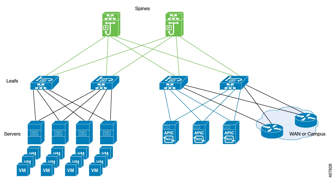
High Availability Deployment for Application Centric Infrastructure (ACI) Network

Information About Deploying ACI Network in Controller

Cisco Application Centric Infrastructure (ACI) technology integrates virtual and physical workloads in a programmable and multihypervisor fabric to build a multiservice or a cloud data center.


Note


The Cisco ACI technology is supported only in a Redundancy Management Interface (RMI) high-availability network.


The following figure depicts the discrete components connected in a spine and leaf switch topology provisioned and managed as a single entity.

Figure 1. Cisco ACI Network Deployment

The following mechanisms help avoid interleaving traffic.

Bringing Down Wireless Management Interface Faster

In case of a switchover in ACI deployments, APs and clients are dropped because of interleaving traffic between the old and the new active controller. To resolve this issue, bring down the traffic from the old active controller faster. You can do this by bringing down the wireless management interface as soon as a failure is detected. When the wireless management interface shuts down, the traffic that is sourced from the old active wireless management interface stops. This avoids conflicts in the management IP address. The standby controller transitions to the role of the active controller with a new IP-MAC binding.


Note


The IP Data-Plane Learning feature in an ACI deployment tracks the following:

  • A duplicate MAC address for the same IP.

  • Alarm that blocks the IP address for a configured duration.


During failure detection, the controller sets up the chassis property non-participant . In IP Data-Plane Learning feature, listen to the property for bringing down the wireless management interface and shutting down traffic in the old active controller faster, thereby avoiding any kind of interleaving traffic between the old and new active controllers.

Disabling Fast Switchover Notification

This mechanism provides more control to avoid interleaving traffic.

During failure handling, the active controller sends an explicit notification to the standby controller, stating that it is going down. This triggers the standby node to take over as the active node. In the event of failure, you can use the disable fast switchover notification option to control the explicit notification from active to standby. In the absence of explicit notification, the standby controller takes over as the active controller on the basis of keepalive timeout.


Note


You can configure the keepalive timeout so that you have control over when the traffic from the new active controller begins if a failure occurs. In such a failure scenario, the switchover also gets delayed.


When you enable this option, the active controller cannot send an explicit failure notification message to the standby controller. The standby controller relies solely on the keepalive timeout failures to detect when the active controller went down.

This delays the keepalive timeout in the commencing traffic in the new active controller, thus avoiding the overlapping traffic from the old active controller. Therefore, disabling fast switchover notification increases the switchover duration by the additional keepalive timeout duration.

GARP Burst

During a controller switchover event, the GARP traffic is generated in burst that overwhelms the ARP learning of ACI. This feature devises a way to retransmit the GARP packet at a much lower rate after a switchover from a new active controller.

Prerequisite for Deploying the ACI Network in the Controller

Check the maximum supported clients in High Availability to ensure that Cisco ACI does not exceed the configured IPv4 and IPv6 end points.

Disabling the Fast Switchover Notification Mechanism (CLI)

Procedure

  Command or Action Purpose

Step 1

configure terminal

Example:

Device# configure terminal

Enters global configuration mode.

Step 2

no redun-management fast-switchover

Example:

Device(config)# no redun-management fast-switchover

Disables explicit fast switchover notification.

Note


Configure the fast switchover notification mechanism in the primary controller. This configuration is not required in the secondary controller.

Step 3

end

Example:

Device(config)# end

Returns to privileged EXEC mode.

Configuring Gratuitous ARP (GARP) Retransmit (CLI)

Procedure

  Command or Action Purpose

Step 1

configure terminal

Example:

Device# configure terminal

Enters global configuration mode.

Step 2

redun-management garp-retransmit burst packet-burst-size interval time-interval

Example:

Device(config)# redun-management garp-retransmit burst 0 interval 0

Determines the rate at which the GARP resend is performed.

Note

 
  • packet-burst-size : The valid range is from 0 to 1000. The value 0 refers to the disabled retransmit.

  • time-interval : Refers to the time interval, in seconds. The valid range is from 0 to 5 seconds. The value 0 refers to the disabled retransmit.

Step 3

end

Example:

Device(config)# end

Returns to privileged EXEC mode.

Disabling Initial GARP (CLI)

Procedure

  Command or Action Purpose

Step 1

configure terminal

Example:

Device# configure terminal

Enters global configuration mode.

Step 2

no redun-management garp-retransmit initial

Example:

Device(config)# no redun-management garp-retransmit initial

Disables the initial GARP.

Step 3

end

Example:

Device(config)# end

Returns to privileged EXEC mode.

Configuring a Switchover

Procedure

Command or Action Purpose

To force a failover to the standby unit, use the following command:

Example:

Device#redundancy force-switchover

In this case, the standby controller will take the role of the active controller, and the active controller will reload and become the new standby controller. This command can be used to test the stability of the high availability cluster and see if switchovers are working as expected.

Note


Do not use any other command to test switchovers between the Cisco Catalyst 9800 series wireless controllers. Command such as "reload slot X" (where X is the active controller) might lead to unexpected behaviour and should not be used to perform a switchover.

Note


In a scaled environment, it is recommended to not perform an immediate switchover after the WLAN or policy profile configurations are modified as it might lead to unexpected behaviour.

Redundancy Management Interfaces

The Redundancy Management Interface (RMI) is a key feature for high availability (HA) in Cisco Catalyst 9800 Series Wireless Controllers. This chapter presents foundational concepts, processes, reference tables, configuration tasks, and principles related to RMI, its pairing scenarios, gateway monitoring, and troubleshooting. It covers information for both IPv4 and IPv6 dual stack support, dynamic pairing, upgrade/downgrade behaviors, and the configuration of gateway monitoring, as well as practical recommendations for ARP handling and AAA integration.

Redundancy management interfaces

A redundancy management interface is a network interface that

  • acts as a secondary link between active and standby wireless controllers,

  • enables resource health information exchange (such as gateway reachability), and

  • assists in the detection of dual-active controller conditions to maintain high availability.

The RMI might trigger a switchover based on the gateway status of the active controller.

Subdefinitions:

  • Active controller: Uses the management IP as the primary address and RMI as the secondary IPv4 address on the management VLAN. RMI configuration is automatic.

    Analogy: Like a city’s current mayor who’s in charge, but always ready to hand over leadership if needed.

  • Standby controller: Has the RMI IP as the primary address; upon switchover, roles and addresses are swapped.

    Analogy: Like a vice-mayor who takes the mayor’s seat (with all responsibilities and keys) when the mayor is away.

  • RP (Redundancy Port): The main dedicated physical link for state and configuration synchronization between active and standby controllers; loss of both RP and RMI links results in high availability (HA) failures.

    (Analogy: Like the main road connecting two city offices, critical for daily business and coordination).

  • WMI (Wireless Management Interface): The main management interface for controller operations and communications; shares its subnet with the RMI and may serve as a source address for certain types of traffic such as AAA packets.

    Analogy: Like a city’s public headquarters, used for both regular operations and official correspondence.

  • RMI (Redundancy Management Interface): A dedicated network interface that serves as a secondary communication path between controllers for exchanging resource health information, detecting dual-active conditions, and monitoring gateway reachability; shares the same subnet as the Wireless Management Interface (WMI).

    Analogy: Like an emergency side road connecting two city halls, used for urgent official communication.

  • HA (High Availability): A deployment setup where controllers operate as an active-standby pair to ensure uninterrupted wireless services; relies on RP and RMI links for failover and role management.

  • ARP table: A database on a network device such as a switch that maintains mappings between IP addresses and MAC addresses; determines how to forward traffic within the local network.

    (Analogy: Like a city map book held by delivery drivers in neighboring towns, showing them which mayor is at which city hall, so the right deliveries go to the right address.)

  • GARP (Gratuitous ARP): A type of ARP (Address Resolution Protocol) packet broadcast by a controller, typically after a switchover, to update the ARP tables in connected network switches with the correct IP-to-MAC address mappings.

    (Analogy: Like sending out an urgent memo to all nearby towns, telling them who the new mayor is so they update their city maps immediately after a leadership change.)

  • ARP cache timeout: The duration for which an entry in the ARP table is considered valid before it must be refreshed; reducing this value helps the network recover quickly after role or address changes in the controllers.

    (Analogy: Like setting a regular schedule for when all delivery drivers check for updates to the city map books, ensuring they quickly recognize changes in city leadership or addresses.)

  • SGACL (Security Group Access Control List): A policy configuration that determines which types of network traffic (e.g., ICMP, ARP) are permitted between specific interfaces or devices, such as the RMI addresses of controllers.

    (Analogy: Like special city rules that decide which types of emergency vehicles are allowed to travel the emergency road between city halls.)

  • ICMP (Internet Control Message Protocol): A network protocol used for sending error messages and operational information between network devices; essential for controllers to monitor each other’s status over the RMI.

    (Analogy: Like sending quick bike couriers to report on the status of the roads or to alert if there’s trouble between cities.)

  • AAA (Authentication, Authorization, and Accounting): A framework for controlling user access to network resources and tracking user activity; controllers may send AAA-related packets from either the WMI IP or the RMI IP, so the AAA server must recognize both as valid.

    (Analogy: Like having a security checkpoint that logs who enters or exits city buildings, whether they come from Main Street (WMI) or the emergency road (RMI).)

  • SGT (Security Group Tag): An identification label assigned to network devices for policy enforcement with Cisco TrustSec; mapping is applied for both RMI and WMI addresses when device SGTs are used.

    Analogy: Like giving every city vehicle a badge, so officials can enforce special rules for each group whether they use Main Street or the emergency road.

  • Cisco TrustSec: A security architecture that uses SGTs to enforce network segmentation and access control policies; not supported on the RMI interface.

    Analogy: Like a city’s security zone system—effective on main city roads, but not supported on the emergency side road.

Limitations for RMI

  • Cisco TrustSec is not supported on the RMI.

  • From the Cisco IOS XE 17.14.1 release onwards, RP-only SSO is not supported for CW9800H1, CW9800H2, or CW9800M Wireless Controllers. These controllers support RP+RMI SSO deployment only. In contrast, Cisco Catalyst 9800 Wireless Controllers support both RP-only SSO and RP+RMI SSO.

Best practices for RMI

  • Ensure that the SGACL is defined appropriately to allow ICMP and ARP traffic between the active and standby RMI addresses when device SGT is used, since the IP-SGT mapping applies to both the RMI and WMI addresses.

  • Configure the AAA server to recognize both the WMI IP and the RMI IP as valid source addresses, because AAA packets from the controller may originate from either.

Important: gateway monitoring interval and detection time

  • When gateway reachability is enabled, both the active and standby controllers check gateway status through the RMI interface.

  • It takes approximately the configured gateway monitoring interval to detect when a controller has lost gateway reachability.

  • The default gateway monitoring interval is eight seconds, so the minimum detection time is about eight seconds unless you configure a different value.

Recommendation: set ARP cache timeout to ensure fast HA recovery:

When both the RP and RMI links are down, the HA setup breaks and both controllers become active, causing an IP conflict in the network. The HA setup is restored once the RP link is up. Depending on the external switch, its ARP table may correctly update to the new active controller or remain stale if the switch ignores GARP packets, potentially prolonging the conflict.

  • We recommend setting the ARP cache timeout to a low value. This practice enables faster recovery from multiple fault scenarios.

    You should choose a timeout value that does not negatively affect network traffic. For example, 30 minutes is a suitable interval.

Analogy

Think of redundancy management interfaces (RMI) as an emergency backup road that connects two cities (the active and standby controllers). The main highway (the redundancy port, RP) handles most of the day-to-day traffic and coordination. If the main highway is blocked or damaged, the emergency road (RMI) ensures that vital information—such as each city's health, status, and road conditions—can still be exchanged quickly.

Just as emergency vehicles and communication must be allowed to travel the backup road (analogous to allowing ICMP and ARP traffic via SGACL), the RMI helps both cities detect if both try to take charge at the same time (dual-active condition) and exchange important information about the area's main gateway (gateway status). If both the highway and the emergency road are inaccessible, each city might assume it’s in charge, resulting in confusion (an IP conflict). The ARP table is like city maps in other towns (switches) that may not immediately recognize which city is currently in charge after both reconnect—setting these maps to update frequently (low ARP cache timeout) allows for faster recovery from major outages.

Active or Standby Controller Operations with RMI

The active controller assigns IP addresses as follows:

  • The primary address is the management IP address.

  • The secondary IPv4 address on the management VLAN is the RMI (Redundant Management Interface) IP address for the active controller.

The standby controller manages IP addresses in a high-availability setup as follows:

  • It does not have the wireless management IP configured.

  • The RMI IP address is configured as the primary IP address on the standby controller.

  • When the standby controller becomes active, the management IP address becomes the primary IP address, and the RMI IP address becomes the secondary IP address.

  • If the interface on the active controller is administratively down, the same state is reflected on the standby controller


Note


Do not configure the secondary IPv4 address explicitly. RMI automatically configures a single secondary IPv4 address under the RMI.


Dual stack support on management VLAN with RMI

A dual stack configuration is a network interface setup that

  • allows both IPv4 and IPv6 addresses to be configured on the wireless management interface,

  • permits monitoring only of the gateway that matches the configured RMI address family (IPv4 or IPv6), and

  • restricts the visibility of the alternate family’s management address on the standby controller.

Expanded Explanation

  • Dual stack refers to the fact that the wireless management interface can be configured with IPv4 and IPv6 addresses. If an RMI IPv4 address is configured along with an IPv4 management IP address, you can additionally configure an IPv6 management address on the wireless management interface. This IPv6 management IP address will not be visible on the standby controller.

  • If an RMI IPv6 address is configured along with an IPv6 management IP address, you can additionally configure an IPv4 management address on the wireless management interface. This IPv4 management IP address will not be visible on the standby controller.

  • Therefore, you can monitor only the IPv6 gateway when the RMI IPv6 address is configured, or only the IPv4 gateway when the RMI IPv4 address is configured.


Note


The RMI feature supports the RMI IPv4 or IPv6 addresses.


RMI-Based High-Availability Pairings

A RMI-based high-availability pair is a controller deployment configuration that:

  • uses Remote Machine Interface (RMI) to synchronize two controllers,

  • provides redundancy by designating active and standby roles, and

  • ensures failover and persistent state during controller reloads or outages.

RMI-Based High-Availability Pairing Scenarios and Device Support

You should consider RMI-based high-availability pairs in the following scenarios:

  • Fresh installation: Configure high availability during the initial setup of controllers.

  • Already paired controllers: Adjust or reconfigure pairing for controllers that are already part of a high-availability pair.

  • Upgrade scenario: Maintain or update the pair relationship during software or hardware upgrades.

  • Downgrade scenario: Ensure pairing remains stable and functional during downgrades.

Dynamic high-availability (HA) pairing requires both the active and standby controllers to reload. In practice, on the Cisco Catalyst 9800-L, 9800-40, and 9800-80 Wireless Controllers, dynamic pairing occurs when one controller reloads and becomes the standby member of the pair.


Note


Unique chassis numbers must be configured for each controller before forming an HA pair, as these numbers identify the controllers within the pair.


HA Pairing Without Previous Configuration

A high-availability (HA) pairing without previous configuration is a deployment scenario for wireless controllers that:

  • initiates the HA setup on devices without existing ROMMON variables for RP (Route Processor) IP addresses,

  • allows selection between the soon-to-be-deprecated privileged EXEC mode RP-based commands and the newer RMI IP-based mechanisms, and

  • derives RP IPs from RMI IPs after forming the HA pair, with restrictions on method transitions.

Additional reference information

  • When HA pairing is performed for the first time (without previous setup), devices do not have ROMMON variables for RP IP addresses.

  • After RMI-based HA pairing on a brand-new system:

    • RP IPs are derived from RMI IPs and used in HA pairing.

    • Privileged EXEC mode RP-based CLIs method of clearing and forming an HA pair is not allowed.

    • To view the ROMMON variables, use the show romvars command.

Command usage and method selection


Caution


Privileged EXEC mode RP-based commands are deprecated and will be blocked after choosing the RMI-based HA pairing.


  • You can still choose from the existing privileged EXEC mode RP-based commands or the RMI IP-based mechanisms. However, the privileged EXEC mode RP-based commands are deprecated.

  • If you use Cisco Catalyst Center, you can choose the privileged EXEC mode RP-based CLI mechanism till the Cisco Catalyst Center migrates to support the RMI.

  • If you choose privileged EXEC RP-based CLI mechanism, the RP IPs are configured the same way as in the 16.12 release.

Best practice: use RMI IP-based for fresh installations

Use the RMI IP-based mechanism for fresh installations, even though both RP-based and RMI methods may initially be available.

Software version considerations

Use the RMI IP-based mechanism for fresh installations, even though both RP-based and RMI methods may initially be available.

  • The RMI migration is supported from Cisco Catalyst Center, 2.3.3.x release version.

  • RMI-based High Availability requires Cisco IOS XE release version 17.3 or above.

Interoperability with Cisco Catalyst Center

  • If you use Cisco Catalyst Center, you can choose the privileged EXEC mode RP-based CLI mechanism till the Cisco Catalyst Center migrates to support the RMI.

  • The RMI migration is supported from Cisco Catalyst Center, 2.3.3.x release version.

Compatibility and limitations during RMI migrations

Negative cases where RMI migration fails include:

  • Devices are not reachable.

  • Non-Cisco Catalyst 9800 Series Wireless Controllers are in use.

  • Controller is running Cisco IOS XE 17.3 or below

  • High Availability is not configured.

  • High Availability RMI is already configured.

  • Attempting upgrade to an already failed High Availability paired controller.


Caution


The controller GUI prohibits applying RMI migration configuration to High Availability failed devices.


Analogy

Establishing HA pairing without previous configuration is like setting up a new security system in a building that has never had one before.

At first, you have the choice between using an old key-based system (privileged EXEC mode RP-based commands), which will soon be phased out, or installing a new state-of-the-art digital access system (RMI IP-based mechanism).

Once you install the modern digital system and program it to generate security codes based on the latest technology (RP IPs derived from RMI IPs), the use of physical keys becomes unavailable.

If you later decide to upgrade, you can only add new features to the digital system; you cannot go back to using the old keys because the doors no longer have compatible locks.

This analogy illustrates how choosing the RMI-based approach in HA pairing establishes a new baseline that does not allow reverting to the older method.

Paired controllers

A paired controller is a high availability (HA) infrastructure configuration that

  • links two controllers to operate jointly for redundancy and failover,

  • allows seamless migration from traditional EXEC mode RP-based commands to RMI-based HA pairing, and

  • ensures controller identity and connectivity are maintained even when core pairing mechanisms are updated or reloaded.

Expanded explanation

When controllers are already in an HA pair, they continue to use existing EXEC mode RP-based commands unless Remote Management Interface (RMI) is enabled. Enabling RMI migrates the system to use RMI-derived HA pairing, overwriting any existing RP IPs with those derived from the RMI configuration. The HA pair remains stable immediately after this change, but the controllers only adopt the new IPs following their next reload.

RMI requires controllers to be reloaded for the changes to take effect. Once both controllers restart, they reestablish the HA pair using the new RMI-derived RP IPs. After pairing through RMI, EXEC mode RP-based commands are blocked, preventing configuration conflicts

Examples

  • Two controllers configured as a high availability pair, where enabling RMI changes the way their active-standby relationship is managed and what IPs are used for internal communication.

  • An active and standby controller pair that continues functioning during migration from legacy RP-IP pairing to RMI, without disruption until reload.

Counter-examples

  • Two standalone controllers operating independently without HA pairing cannot be considered paired controllers.

  • A controller pair where RMI is never configured and all management remains through EXEC mode RP-based commands does not benefit from RMI-derived features.

Analogy

Imagine a paired controller setup as two co-pilots flying an airplane together (the airplane represents your network environment). Traditionally, they use walkie-talkies (EXEC mode RP-based commands) to coordinate their flying activities. If you upgrade their communication system to headsets (RMI-based pairing), the co-pilots continue flying the plane using walkie-talkies until they both put on the new headsets (after a "reload" or restart). From that point onward, all their coordination happens via the more reliable and advanced headsets. The co-pilots' ability to work together—their partnership—remains unbroken throughout; it is only how they communicate and identify each other’s messages that changes, and only becomes effective after both are using the new headsets.

Upgrading from Cisco IOS XE 16.1.x to a Later Release

When upgrading a system, you have the following options:

  • Migrate while retaining the existing RP IP configuration: In this scenario, the current RP IP configuration remains unchanged, and future modifications will utilize EXEC mode RP-based commands.

  • Migrate after clearing the HA configuration: Here, you have the choice to use either the traditional EXEC mode RP-based commands or adopt the new RMI-based RP configuration. If the previous configuration is preserved, RMI will update the RP IPs with those derived from the RMI IPs.

Downgrade Scenario


Important


The downgrade scenario given below is not applicable for Cisco IOS XE Amsterdam 17.1.x.


In a downgrade scenario, only EXEC mode RP-based commands are available. The downgrade process may follow one of these paths:

  • If the upgraded system used the RMI-based RP configuration.

  • If the upgraded system continued to use the EXEC mode RP-based commands.

In the above cases, the downgraded system uses the EXEC mode RP-based commands to modify the configuration. However, the downgraded system will continue to use the new derived RP IPs.

In both of these cases, the system will revert to EXEC mode RP-based commands for configuration alterations, yet will still utilize the newly derived RP IPs.


Note


When you downgrade the Cisco Catalyst 9800 Series Wireless Controller to any version below 17.1 and if the mDNS gateway is enabled on the WLAN/RLAN/GLAN interfaces, the mdns-sd-interface gateway goes down after the downgrade.

To enable the mDNS gateway on the WLAN/RLAN/GLAN interfaces in 16.12 and earlier versions, use the following commands:

wlan test 1 test

mdns-sd gateway

To enable the mDNS gateway on the WLAN/RLAN/GLAN interfaces from version 17.1 onwards, use the following command:

mdns-sd-interface gateway


Configure Redundancy Management Interface (GUI)

Enable redundancy management for Cisco Catalyst 9800 Series Wireless Controllers using the graphical user interface (GUI).

Use this task to configure the redundancy management interface (RMI) and set up either RMI+RP or RP redundancy pairing on Cisco Catalyst 9800 Series Wireless Controllers. Configuring redundancy improves system availability and failover capabilities

Before you begin

Ensure that Wireless Management Interface (WMI) is available before configuring RMI + RP using the GUI.

Procedure


Step 1

In the Administration > Device > Redundancy window, perform the following:

  1. Set the Redundancy Configuration toggle button to Enabled to activate redundancy configuration.

  2. In the Redundancy Pairing Type field, select RMI+RP to perform RMI+RP redundancy pairing as follows:

    • In the RMI IP for Chassis 1 field, enter the RMI IP address for chassis 1.

    • In the RMI IP for Chassis 2 field, enter the RMI IP address for chassis 2.

    • From the HA Interface drop-down list, choose one of the HA interfaces.

      You can select the HA interface only for Cisco Catalyst 9800 Series Wireless Controllers.

    • Set the Management Gateway Failover toggle button to Enabled to activate management gateway failover.

    • In the Gateway Failure Interval field, enter an appropriate value. The valid range is 6–12 seconds (default 8 seconds).

  3. In the Redundancy Pairing Type field, select RP to perform RP redundancy pairing as follows:

    • In the Local IP field, enter an IP address for the local chassis.

    • In the Netmask field, enter the subnet mask assigned to all wireless clients.

    • From the HA Interface drop-down list, choose one of the HA interfaces.

      You can select the HA interface only for Cisco Catalyst 9800 Series Wireless Controllers.

    • In the Remote IP field, enter an IP address for the remote chassis.

  4. In the Keep Alive Timer field, enter an appropriate timer value (1–10 ×100 milliseconds).

  5. In the Keep Alive Retries field, enter an appropriate retry value (3–10 seconds).

  6. In the Active Chassis Priority field, enter a value.

Step 2

Click Apply and reload controllers.


The redundancy management interface is configured, and redundancy pairing is established based on your chosen method. The controller is now set up for improved high availability and failover.

Configure Redundancy Management Interface (CLI)

Purpose: Configure a Redundancy Management Interface (RMI) on Cisco Catalyst 9800 controllers using CLI commands to support high availability (HA) between two devices.

Context: Use this task when you want to set up high availability and redundancy between two Catalyst 9800 series controllers. The RMI coordinates HA communication and failover, ensuring service continuity in case of device failure.

Before you begin

  • Ensure both controllers are cabled and powered on.

  • Verify you have administrator access to both devices via CLI.

  • Gather the following information:

    • Chassis number (1 or 2 for each controller)

    • Desired chassis priority for HA (if overriding default)

    • A dedicated GigabitEthernet interface for HA communication (required for 9800-CL controllers)

    • Management VLAN and corresponding IP addresses for each chassis

Procedure


Step 1

chassis chassis-num priority chassis-priority

Example:

Device# chassis 1 priority 1

(Optional) Configures the priority of the specified device.

From Cisco IOS XE Gibraltar 16.12.x onwards, device reload is not required for the chassis priority to become effective.

  • chassis-num —Enter the chassis number. The range is from 1 to 2.

  • chassis-priority —Enter the chassis priority. The range is from 1 to 2. The default value is 1.

When both the devices boot up at the same time, the device with higher priority becomes active, and the other one becomes standby. If both the devices are configured with the same priority value, the one with the smaller MAC address acts as active and its peer acts as standby.

Step 2

chassis redundancy ha-interface GigabitEthernet interface-number

Example:

Device# chassis redundancy ha-interface 
                        GigabitEthernet 3

Creates an HA interface for your controller.

  • interface-number : GigabitEthernet interface number. The range is from 1 to 32.

This step is applicable only for Cisco Catalyst 9800-CL Series Wireless Controllers. The chosen interface is used as the dedicated interface for HA communication between the 2 controllers.

Step 3

configure terminal

Example:

Device# configure terminal

Enters global configuration mode.

Step 4

redun-management interface vlan vlan-interface-number chassis chassis-number address ip-address chassis chassis-number address ip-address

Example:

Device(config)# redun-management interface                         
Vlan 200 chassis 1 address 9.10.90.147                         
chassis 2 address 9.10.90.149

Configures Redundancy Management Interface.

  • vlan-interface-number : VLAN interface number. The valid range is from 1 to 4094.

    Here, the vlan-interface-number is the same VLAN as the Management VLAN. That is, both must be on the same subnet.

  • chassis-number : Chassis number. The valid range is from 1 to 2.

  • ip-address : Redundancy Management Interface IP address.

Each controller must have a unique chassis number for RMI to form the HA pair. The chassis number can be observed as SWITCH_NUMBER in the output of show romvar command. Modification of SWITCH_NUMBER is currently not available through the web UI.

To disable the HA pair, use the no redun-management interface vlan chassis command.

Step 5

end

Example:

Device(config)# end

Returns to privileged EXEC mode.

Step 6

write memory

Example:

Device# write memory

Saves the configuration.

Step 7

reload

Example:

Device# reload

Reloads the controllers.

When the RMI configuration is done, you must reload the controllers for the configuration to take effect.

For Cisco Catalyst 9800-CL Wireless Controller VM, both the active and standby controllers reload automatically. In the case of hardware platforms, you should reload the active controller manually, as only standby the controller reloads automatically.


The redundancy management interface is configured. After reload, an HA pair is established between the two controllers, enabling redundancy and failover support.

Gateway Monitoring

Gateway Monitoring feature is a network management capability that

  • selects the gateway IP based on the static routes that match the RMI subnet using the broadest mask and least gateway IP

  • provides enhanced visibility and statistics related to gateway reachability and RMI state, and

  • simplifies troubleshooting and control over high availability (HA) and RMI functionality by offering detailed diagnostics.

Key aspects:
  • Gateway IP selection:

    • From Cisco IOS XE Amsterdam 17.2.1 onwards, the ip default-gateway gateway-ip command is deprecated for RMI gateway configuration.

    • The system automatically chooses a gateway IP by evaluating static routes and selecting the gateway that:

      • matches the RMI subnet,

      • uses the broadest subnet mask,

      • and has the lowest IP address.

    • If no matching static route exists, gateway failover does not operate—even if management gateway-failover is enabled.

Analogy: airport's air traffic control system

Gateway monitoring works like an airport’s air traffic control system. Instead of a pilot manually selecting a runway (like using the old ip default-gateway command), a central system automatically identifies the best runway based on current conditions (route matching, subnet mask, and lowest IP address). It then tracks the success or failure of each takeoff and landing (probe statistics and diagnostics), making sure the whole airport runs smoothly and efficiently while providing real-time updates and troubleshooting support when issues arise.

Configuring Gateway Monitoring Interval (CLI)

Set the interval at which the management gateway failover feature monitors gateway availability on a switch.

Adjusting the gateway monitoring interval determines how frequently the device checks gateway status to trigger failover if necessary. This procedure is performed using command-line interface (CLI) commands.

Follow these steps to configure the gateway monitoring interval using the CLI:

Before you begin

  • Ensure you have access to the device CLI in privileged EXEC mode.

  • Confirm that you have the required permissions to enter configuration mode and modify gateway monitoring settings.

Procedure


Step 1

configure terminal

Example:

Device# configure terminal

Enters global configuration mode.

Step 2

management gateway-failover interval interval-value

Example:

Device(config)# management gateway-failover interval 6

Configures the gateway monitoring interval.

interval-value - Refers to the gateway monitoring interval. The valid range is from 6 to 12. Default value is 8.

Step 3

end

Example:

Device(config)# end

Saves the configuration and exits configuration mode and returns to privileged EXEC mode.


The system now monitors the gateway at the specified interval. Your configuration is saved, and the device returns to privileged EXEC mode.

Configure Gateway Monitoring (CLI)

Enable and configure gateway monitoring on a device.

This task is typically performed to ensure that network devices can effectively monitor and manage gateway connections, facilitating smooth network operations and management. Gateway monitoring involves setting up a default gateway and enabling monitoring features.

Procedure


Step 1

configure terminal

Example:

Device# configure terminal

Enters global configuration mode.

Step 2

[no] management gateway-failover enable

Example:

Device(config)# management gateway-failover enable

Enables gateway monitoring. (Use the no form of this command to disable gateway monitoring.)

Step 3

end

Example:

Device(config)# end

Returns to privileged EXEC mode.


The gateway monitoring is enabled and configured, and the configuration changes are active.

What to do next

To save the configuration, use the write memory command.

Gateway Reachability Detection

Information About Gateway Reachability Detection

Gateway Reachability Detection feature mimimizes the downtime on APs and clients when the gateway reachability is lost on the active controller.

Both active and standby controllers keep track of gateway reachability. The gateway reachability is detected by sending Internet Control Message Protocol (ICMP) and ARP requests periodically to the gateway.

Both active and standby controllers use the RMI IP as the source IP. The messages are sent at 1 second interval. If it takes 8 (or configured value) consecutive failures in reaching the gateway, the controller declares the gateway as non-reachable. It takes approximately 8 seconds to detect if a controller has lost gateway reachability.

Gateway monitoring with native IPv6 uses ICMP Neighbor Discovery protocols and ICMPv6 ECHO to check gateway reachability.

Therefore, you can monitor only the IPv6 gateway when RMI IPv6 is configured.

This means that only one IPv4 or IPv6 gateways can be monitored.


Note


If the standby controller loses gateway, the standby moves to the standby recovery mode.

If the active controller loses gateway, the active reloads and standby becomes active.


Migrating to RMI IPv6

From RMI IPv4

  1. Unconfigure the RMI IPv4 using the following CLIs:

    
    Device# conf t
    Device(config)# no redun-management interface <vlan_name> chassis 1 address <ip_address1> chassis 2 address <ip_address2>

    Note


    This CLI unconfigures RMI on both the controllers.


  2. Note


    Take a backup of the running config on active before you reload the controller.


    Reload the controller.

  3. Copy the backed up config to the running config on the box which would have lost all the config.

  4. Configure the RMI IPv6 on both the controllers. For information on the CLI, see .

  5. Reload the controller.

From HA Pairing (Without RMI)

For information on HA pairing, see Configuring Redundancy Management Interface (GUI).

Monitoring the Health of the Standby Controller

The Standby Monitoring feature allows you to monitor the health of a system on a standby controller using programmatic interfaces and commands. This feature allows you to monitor parameters such as CPU, memory, interface status, power supply, fan failure, and the system temperature. Standby Monitoring is enabled when Redundancy Management Interface (RMI) is configured, no other configuration is required. The RMI itself is used to connect to the standby and perform standby monitoring. Standby Monitoring feature cannot be dynamically enabled or disabled.


Note


The active controller uses the management or RMI IP to initiate AAA requests. Whereas, the standby controller uses the RMI IP to initiate AAA requests. Thus, the RMI IPs must be added in AAA servers for a seamless client authentication and standby monitoring.


To enable standby console, ensure that the following configuration is in place:

redundancy
main-cpu
secondary console enable

Note


The Standby Monitoring feature is not supported on a controller in the active-recovery and the standby-recovery modes.


The Standby Monitoring feature supports only the following traffic on the RMI interface of the standby controller:

  • Address Resolution Protocol (ARP)

  • Internet Control Message Protocol (ICMP)

  • TCP Traffic (to or from) ports: 22, 443, 830, and 3200

  • UDP RADIUS ports:1645 and1646

  • UDP Extended RADIUS ports: 21645 to 21844

Feature Scenarios

  • To monitor the health of the standby directly from the standby controller using Standby RMI IP.

  • To get syslogs from the standby controller using the Standby RMI IP.

Use Cases

  • Enabling SNMP agent and programmatic interfaces on the standby controller: You can directly perform an SNMP query or programmatic interface query to the standby’s RMI IP and active controller.

  • Enabling syslogs on the standby controller: You can directly get the standby syslogs from the standby controller.

RADIUS Accounting Support

Whenever you log in to a standby device, the RADIUS start record must be sent to the external RADIUS server. Similarly, when you log out of a device, the RADIUS stop record must be sent to the external RADIUS server.

TACACS+ Authentication Support

Users are authenticated through the RMI using the external TACACS+ server. The username and password are evaluated in the TACACS+ server. Depending on the response received from the server, a user will be able to log in to the standby device.

TACACS+ Accounting Support

Whenever you log in to the standby device, the TACACS+ accounting start record must be sent to the external TACACS+ server. Similarly, when you log out of a device, the TACACS+ accounting stop record must be sent to the external TACACS+ server.


Note


The following configuration must be in place to configure AAA to send the accounting packets:

aaa accounting exec {default | named-list} start-stop group {RAD | tac-group-name}


Note


The TACACS+ login to the standby device is not supported when TACACS+ server is configured with hostname.


Monitoring the Health of Standby Parameters Using SNMP

Standby Monitoring Using Standby RMI IP

When an SNMP agent is enabled on the standby controller, you can directly perform an SNMP query to the standby’s RMI IP. From Release 17.5 onwards, you can query the following MIB on the standby controller:

Table 4. MIB Name and Notes

MIB Name

Notes

IF-MIB

This MIB is used to monitor the interface statistics of the standby controller using the standby RMI IP address.


Note


If an SNMP agent is enabled on the active controller, by default, the SNMP is enabled on the standby controller.


Standby Monitoring Using the Active Controller

CISCO-LWAPP-HA-MIB

The CISCO-LWAPP-HA-MIB monitors the health parameters of the standby controller, that is, memory, CPU, port status, power statistics, peer gateway latencies, and so on.

You can query the following MIB objects of CISCO-LWAPP-HA-MIB.

Table 5. MIB Objects and Notes

MIB Objects

Notes

cLHaPeerHotStandbyEvent

This object can be used to check if the standby controller has turned hot-standby or not.

cLHaBulkSyncCompleteEvent

This object represents the time at which the bulksync is completed.

CISCO-PROCESS-MIB

The CISCO-PROCESS-MIB monitors CPU and process statistics. Use it to monitor CPU-related or memory-related BINOS processes. The standby CISCO-PROCESS-MIB can be monitored using the active controller.

ENTITY-MIB

The ENTITY-MIB is used to monitor hardware details of the active and standby controllers using the active controller.


Note


The standby Route Processor (RP) sensors are appended in the active RP sensors.


Standby IOS Linux Syslogs

The standby logs are relayed using the same method as on the active Cisco IOS for wireless controllers.

From Release 17.5 onwards, external logging of syslogs from the standby IOS is enabled. As BINOS processes on standby also forwards the syslogs to Cisco IOS, all the syslogs generated on the standby controller is forwarded to the configured external server.


Note


RMI IP address is used for logging purpose.


The following is the expected behavior when an HA pair is configured with the RMI IPv6 address, the active controller has dual stack, and logging is configured on the IPv4 address:

The standby controller tries to send syslogs to the IPv4 server because logging is only configured on IPv4 even though IPv4 is not supported by standby.

Standby Interface Status Using Active SNMP

The standby interface information is sent to the active controller using IPC in the following scenarios:

  • When there is a change in the interface status.

  • When a new interface is added or deleted on the standby controller.

When the active controller receives the interface information from the standby controller, the active controller's database is populated with the standby interface information.

When an SNMP query is received for the standby interface information, the SNMP handlers corresponding to the CISCO-LWAPP-HA-MIB reads them from the standby interface database on the active and populates the MIB objects in CISCO-LWAPP-HA-MIB.

You can query the following MIB objects of CISCO-LWAPP-HA-MIB.

Table 6. MIB Objects of CISCO-LWAPP-HA-MIB

MIB Object

Notes

stbyIfIndex

This is a unique value (greater than zero) for each interface of the standby controller.

stbyIfName

This is the name of the standby interface.

stbyIfPhysAddress

This is the interface address of the standby controller in the protocol sublayer.

stbyifOperStatus

This is the current operational state of the interface in the standby controller.

stbyifAdminStatus

This is the desired state of the interface of the standby controller.

To verify the logging on the active when the standby fails to send interface statistics, use the following command:


Device# debug snmp ha-chkpt
Device# debug snmp ha-intf_db

Monitoring the Health of Standby Controller Using Programmatic Interfaces

You can monitor parameters such as CPU, memory, sensors, and interface status on a standby controller using programmatic interfaces such as NETCONF and RESTCONF. The RMI IP of the standby controller can be used for access to the following operational models:

The models can be accessed through .

  • Cisco-IOS-XE-device-hardware-oper.yang

  • Cisco-IOS-XE-process-cpu-oper.yang

  • Cisco-IOS-XE-platform-software-oper.yang

  • Cisco-IOS-XE-process-memory-oper.yang

  • Cisco-IOS-XE-interfaces-oper.yang

For more information on the YANG models, see the Programmability Configuration Guide, Cisco IOS XE Amsterdam 17.3.x.

Monitoring the Health of Standby Controller Using CLI

This section describes the different commands that can be used to monitor the standby device.

You can connect to the standby controller through SSH using the RMI IP of the standby controller. The user credentials must have been configured already. Both local authentication and RADIUS authentication are supported.


Note


The redun-management command needs to be configured on both the controllers, primary and standby, prior to high availability (HA) pairing.


Monitoring Port State

The following is a sample output of the show interfaces interface-name command:

Device-standby# show interfaces GigabitEthernet1        

GigabitEthernet1 is down, line protocol is down                                 
Shadow state is up, true line protocol is up
  Hardware is CSR vNIC, address is 000c.2909.33c2 (bia 000c.2909.33c2)
  MTU 1500 bytes, BW 1000000 Kbit/sec, DLY 10 usec,
     reliability 255/255, txload 1/255, rxload 1/255
  Encapsulation ARPA, loopback not set
  Keepalive set (10 sec)
  Full Duplex, 1000Mbps, link type is force-up, media type is Virtual
  output flow-control is unsupported, input flow-control is unsupported
  ARP type: ARPA, ARP Timeout 04:00:00
  Last input 00:00:06, output 00:00:24, output hang never
  Last clearing of "show interface" counters never
  Input queue: 30/375/0/0 (size/max/drops/flushes); Total output drops: 0
  Queueing strategy: fifo
  Output queue: 0/40 (size/max)
  5 minute input rate 389000 bits/sec, 410 packets/sec
  5 minute output rate 0 bits/sec, 0 packets/sec
     3696382 packets input, 392617128 bytes, 0 no buffer
     Received 0 broadcasts (0 multicasts)
     0 runts, 0 giants, 0 throttles
     0 input errors, 0 CRC, 0 frame, 0 overrun, 0 ignored
     0 watchdog, 0 multicast, 0 pause input
     18832 packets output, 1218862 bytes, 0 underruns
     Output 0 broadcasts (0 multicasts)
     0 output errors, 0 collisions, 2 interface resets
     3 unknown protocol drops
     0 babbles, 0 late collision, 0 deferred
     0 lost carrier, 0 no carrier, 0 pause output
     0 output buffer failures, 0 output buffers swapped out

The following is a sample output of the show ip interface brief command:

Device# show ip interface brief

Interface              IP-Address      OK? Method Status                Protocol
GigabitEthernet1       unassigned      YES unset  down                  down    
GigabitEthernet0       unassigned      YES NVRAM  administratively down down    
Capwap1                unassigned      YES unset  up                    up      
Capwap2                unassigned      YES unset  up                    up      
Capwap3                unassigned      YES unset  up                    up           
Capwap10               unassigned      YES unset  up                    up      
Vlan1                  unassigned      YES NVRAM  down                  down    
Vlan56                 unassigned      YES unset  down                  down    
Vlan111                111.1.1.85      YES NVRAM  up                    up   

Monitoring CPU or Memory

The following is a sample output of the show process cpu sorted 5sec command:

Device-standby# show process cpu sorted 5sec

CPU utilization for five seconds: 0%/0%; one minute: 0%; five minutes: 0%
 PID Runtime(ms)     Invoked      uSecs   5Sec   1Min   5Min TTY Process 
  10     1576556      281188       5606  0.15%  0.05%  0.05%   0 Check heaps      
 232      845057    54261160         15  0.07%  0.05%  0.06%   0 IPAM Manager     
 595         177         300        590  0.07%  0.02%  0.01%   2 Virtual Exec     
 138     1685973   108085955         15  0.07%  0.08%  0.08%   0 L2 LISP Punt Pro 
 193       19644      348767         56  0.07%  0.00%  0.00%   0 DTP Protocol     
   5           0           1          0  0.00%  0.00%  0.00%   0 CTS SGACL db cor 
   4          24          15       1600  0.00%  0.00%  0.00%   0 RF Slave Main Th 
   6           0           1          0  0.00%  0.00%  0.00%   0 Retransmission o 
   7           0           1          0  0.00%  0.00%  0.00%   0 IPC ISSU Dispatc 
   2      117631      348801        337  0.00%  0.00%  0.00%   0 Load Meter       
   8           0           1          0  0.00%  0.00%  0.00%   0 EDDRI_MAIN       


To check CPU and memory utilization of binOS processes, run the following command:

Device-standby# show platform software process slot chassis standby R0 monitor 

top - 23:24:14 up 8 days, 3:38, 0 users, load average: 0.69, 0.79, 0.81 
Tasks: 433 total, 1 running, 431 sleeping, 1 stopped, 0 zombie 
%Cpu(s): 1.7 us, 2.8 sy, 0.0 ni, 95.6 id, 0.0 wa, 0.0 hi, 0.0 si, 0.0 st
MiB Mem : 32059.2 total, 21953.7 free, 4896.8 used, 5208.6 buff/cache 
MiB Swap: 0.0 total, 0.0 free, 0.0 used. 26304.6 avail Mem 

PID USER PR NI VIRT RES SHR S %CPU %MEM TIME+ COMMAND
23565 root 20 0 2347004 229116 130052 S 41.2 0.7 5681:44 ucode_pkt+
2306 root 20 0 666908 106760 46228 S 5.9 0.3 15:06.14 smand 
22807 root 20 0 3473004 230020 152120 S 5.9 0.7 510:56.90 fman_fp_i+
1 root 20 0 14600 11324 7424 S 0.0 0.0 0:31.07 systemd 
2 root 20 0 0 0 0 S 0.0 0.0 0:00.28 kthreadd 
3 root 0 -20 0 0 0 I 0.0 0.0 0:00.00 rcu_gp 
4 root 0 -20 0 0 0 I 0.0 0.0 0:00.00 rcu_par_gp
6 root 0 -20 0 0 0 I 0.0 0.0 0:00.00 kworker/0+
7 root 20 0 0 0 0 I 0.0 0.0 0:00.49 kworker/u+
8 root 0 -20 0 0 0 I 0.0 0.0 0:00.00 mm_percpu+
9 root 20 0 0 0 0 S 0.0 0.0 0:03.26 ksoftirqd+
.
.
.
32258 root 20 0 57116 3432 2848 S 0.0 0.0 0:00.00 rotee
32318 root 20 0 139560 9500 7748 S 0.0 0.0 0:55.67 pttcd
32348 root 20 0 31.6g 3.1g 607364 S 0.0 9.8 499:12.04 linux_ios+
32503 root 20 0 3996 3136 2852 S 0.0 0.0 0:00.00 stack_snt+
32507 root 20 0 3700 1936 1820 S 0.0 0.0 0:00.00 sntp

Monitoring Hardware

The following is a sample output of the show environment summary command:

Device# show environment summary


Number of Critical alarms:  0
Number of Major alarms:     0
Number of Minor alarms:     0

 Slot        Sensor          Current State   Reading        Threshold(Minor,Major,Critical,Shutdown)
 ----------  --------------  --------------- ------------   ---------------------------------------
 P0          Vin             Normal          231  V AC   	na
 P0          Iin             Normal          2    A      	na
 P0          Vout            Normal          12   V DC   	na
 P0          Iout            Normal          30   A      	na
 P0          Temp1           Normal          25   Celsius	(na ,na ,na ,na )(Celsius)
 P0          Temp2           Normal          31   Celsius	(na ,na ,na ,na )(Celsius)
 P0          Temp3           Normal          37   Celsius	(na ,na ,na ,na )(Celsius)
 R0          VDMB1: VX1      Normal          1226 mV     	na
 R0          VDMB1: VX2      Normal          6944 mV     	na
 R0          Temp: DMB IN    Normal          26   Celsius	(45 ,55 ,65 ,70 )(Celsius)
 R0          Temp: DMB OUT   Normal          40   Celsius	(70 ,75 ,80 ,85 )(Celsius)
 R0          Temp: Yoda 0    Normal          54   Celsius	(95 ,105,110,115)(Celsius)
 R0          Temp: Yoda 1    Normal          62   Celsius	(95 ,105,110,115)(Celsius)
 R0          Temp: CPU Die   Normal          43   Celsius	(100,110,120,125)(Celsius)
 R0          Temp: FC FANS   Fan Speed 70%   26   Celsius	(29 ,39 ,0  )(Celsius)
 R0          VDDC1: VX1      Normal          1005 mV     	na
 R0          VDDC1: VX2      Normal          7084 mV     	na
 R0          VDDC2: VH       Normal          12003mV     	na
 R0          Temp: DDC IN    Normal          25   Celsius	(55 ,65 ,75 ,80 )(Celsius)
 R0          Temp: DDC OUT   Normal          35   Celsius	(75 ,85 ,95 ,100)(Celsius)
 P0          Stby Vin        Normal          230  V AC   	na
 P0          Stby Iin        Normal          2    A      	na
 P0          Stby Vout       Normal          12   V DC   	na
 P0          Stby Iout       Normal          32   A      	na
 P0          Stby Temp1      Normal          24   Celsius	(na ,na ,na ,na )(Celsius)
 P0          Stby Temp2      Normal          29   Celsius	(na ,na ,na ,na )(Celsius)
 P0          Stby Temp3      Normal          35   Celsius	(na ,na ,na ,na )(Celsius)
 R0          Stby VDMB1: VX1 Normal          1225 mV     	na
 R0          Stby VDMB1: VX2 Normal          6979 mV     	na
 R0          Stby VDMB2: VX2 Normal          5005 mV     	na
 R0          Stby VDMB2: VX3 Normal          854  mV     	na
 R0          Stby VDMB3: VX1 Normal          972  mV     	na
 R0          Stby Temp: DMB INormal          22   Celsius	(45 ,55 ,65 ,70 )(Celsius)
 R0          Stby Temp: DMB ONormal          32   Celsius	(70 ,75 ,80 ,85 )(Celsius)
 R0          Stby Temp: Yoda Normal          43   Celsius	(95 ,105,110,115)(Celsius)
 R0          Stby Temp: Yoda Normal          45   Celsius	(95 ,105,110,115)(Celsius)
 R0          Stby Temp: CPU DNormal          33   Celsius	(100,110,120,125)(Celsius)
 R0          Stby Temp: FC FAFan Speed 70%   22   Celsius	(29 ,39 ,0  )(Celsius)
 R0          Stby VDDC1: VX1 Normal          1005 mV     	na
 R0          Stby VDDC1: VX2 Normal          7070 mV     	na
 R0          Stby VDDC2: VX2 Normal          752  mV     	na
 R0          Stby VDDC2: VX3 Normal          750  mV     	na
 R0          Stby Temp: DDC INormal          22   Celsius	(55 ,65 ,75 ,80 )(Celsius)
 R0          Stby Temp: DDC ONormal          28   Celsius	(75 ,85 ,95 ,100)(Celsius)

Note


The command displays both active and standby hardware details.


Note


The show environment summary command displays data only for physical appliances such as Cisco Catalyst 9800-80 Wireless Controller, Cisco Catalyst 9800-40 Wireless Controller, Cisco Catalyst 9800-L Wireless Controller, and Cisco Catalyst 9800 Embedded Wireless Controller for Switch. The command does not display data for Cisco Catalyst 9800 Wireless Controller for Cloud.


Verifying the Gateway-Monitoring Configuration

To verify the status of the gateway-monitoring configuration on an active controller, run the following command:

Device# show redundancy states

my state = 13 -ACTIVE
peer state = 8 -STANDBY HOT
Mode = Duplex
Unit = Primary
Unit ID = 1

Redundancy Mode (Operational) = sso
Redundancy Mode (Configured) = sso
Redundancy State = sso
Maintenance Mode = Disabled
Manual Swact = enabled
Communications = Up

client count = 129
client_notification_TMR = 30000 milliseconds
RF debug mask = 0x0
Gateway Monitoring = Disabled
Gateway monitoring interval = 8 secs

To verify the status of the gateway-monitoring configuration on a standby controller, run the following command:

Device-stby# show redundancy states

my state = 8 -STANDBY HOT
peer state = 13 -ACTIVE
Mode = Duplex
Unit = Primary
Unit ID = 2

Redundancy Mode (Operational) = sso
Redundancy Mode (Configured) = sso
Redundancy State = sso
Maintenance Mode = Disabled
Manual Swact = cannot be initiated from this the standby unit
Communications = Up

client count = 129
client_notification_TMR = 30000 milliseconds
RF debug mask = 0x0
Gateway Monitoring = Disabled
Gateway monitoring interval = 8 secs

Verifying the RMI IPv4 Configuration

Verify the RMI IPv4 configuration.

Device# show running-config interface vlan management-vlan

Building configuration...

Current configuration : 109 bytes
!
interface Vlan90
ip address 9.10.90.147 255.255.255.0 secondary
ip address 9.10.90.41 255.255.255.0
end
 

To verify the interface configuration for a standby controller, use the following command:

Device-stby# show running-config interface vlan 90

Building configuration...
 
Current configuration : 62 bytes
!
interface Vlan90
ip address 9.10.90.149 255.255.255.0
end

To verify the chassis redundancy management interface configuration for an active controller, use the following command:

Device# show chassis rmi

Chassis/Stack Mac Address : 000c.2964.1eb6 - Local Mac Address
Mac persistency wait time: Indefinite
			H/W Current
Chassis# Role      Mac Address     Priority  Version  State  IP             RMI-IP
--------------------------------------------------------------------------------------------------------
*1       Active    000c.2964.1eb6  1         V02      Ready  169.254.90.147 9.10.90.147
2        Standby   000c.2975.3aa6  1         V02      Ready  169.254.90.149 9.10.90.149

To verify the chassis redundancy management interface configuration for a standby controller, use the following command:

Device-stby# show chassis rmi

Chassis/Stack Mac Address : 000c.2964.1eb6 - Local Mac Address
Mac persistency wait time: Indefinite
                                             H/W   Current
Chassis#   Role    Mac Address     Priority Version  State  IP              RMI-IP
------------------------------------------------------------------------------------------------
1         Active   000c.2964.1eb6     1      V02     Ready  169.254.90.147  9.10.90.147
*2        Standby  000c.2975.3aa6     1      V02     Ready  169.254.90.149  9.10.90.149

To verify the ROMMON variables on an active controller, use the following command:

Device# show romvar | include RMI

RMI_INTERFACE_NAME = Vlan90
RMI_CHASSIS_LOCAL_IP = 9.10.90.147
RMI_CHASSIS_REMOTE_IP = 9.10.90.149

To verify the ROMMON variables on a standby controller, use the following command:

Device-stby# show romvar | include RMI

RMI_INTERFACE_NAME = Vlan90
RMI_CHASSIS_LOCAL_IP = 9.10.90.149
RMI_CHASSIS_REMOTE_IP = 9.10.90.147

To verify the switchover reason, use the following command:

Device# show redundancy switchover history

Index  Previous  Current  Switchover             Switchover
       active    active   reason                 time
-----  --------  -------  ----------             ----------
   1       2        1     Active lost GW         17:02:29 UTC Mon Feb 3 2020
 

Verifying the RMI IPv6 Configuration

To verify the chassis redundancy management interface configuration for both active and standby controllers, run the following command:

Device# show chassis rmi

Chassis/Stack Mac Address : 00a3.8e23.a540 - Local Mac Address
Mac persistency wait time: Indefinite
Local Redundancy Port Type: Twisted Pair
                                             H/W   Current
Chassis#   Role     Mac Address    Priority Version State     IP             RMI-IP
---------------------------------------------------------------------------------------------
  1        Standby  706d.1536.23c0    1      V02     Ready  169.254.254.17   2020:0:0:1::211
 *2        Active   00a3.8e23.a540    1      V02     Ready  169.254.254.18   2020:0:0:1::212

To verify the RMI related ROMMON variables for both active and standby controllers, run the following command

Device# show romvar | i RMI

RMI_INTERFACE_NAME = Vlan52
RMI_CHASSIS_LOCAL_IPV6 = 2020:0:0:1::212
RMI_CHASSIS_REMOTE_IPV6 = 2020:0:0:1::211

Verifying Redundancy Port Interface Configuration

To verify the RMI link re-establishment count and the time since the RMI link is Up in the active instance, run the following command:

Device# show platform software rif-mgr chassis active R0 rmi-connection-details
RMI Connection Details
    RMI Link re-establish count : 2
    RMI Link Uptime             : 21 hours 8 minutes 43 seconds
    RMI Link Upsince            : 08/05/2021 13:46:01

To verify the RMI link re-establishment count and the time since the RMI link is Down in the active instance, run the following command:

Device# show platform software rif-mgr chassis active R0 rmi-connection-details
RMI Connection Details
    RMI Link re-establish count : 1
    RMI Link Downtime           : 28 seconds
    RMI Link Downsince          : 07/16/2021 03:19:11

To verify the RMI link re-establishment count and the time since the RMI link is Up in the standby instance, run the following command:

Device# show platform software rif-mgr chassis standby R0 rmi-connection-details
RMI Connection Details
    RMI Link re-establish count : 1
    RMI Link Uptime             : 1 hour 39 minute 9 seconds
    RMI Link Upsince            : 07/16/2021 01:31:41

To verify the RMI link re-establishment count and the time since the RMI link is Down in the standby instance, run the following command:

Device# show platform software rif-mgr chassis standby R0 rmi-connection-details
RMI Connection Details
    RMI Link re-establish count : 1
    RMI Link Downtime           : 22 seconds
    RMI Link Downsince          : 07/16/2021 03:19:17

To verify the RP link re-establishment count and the time since the RP link is UP for days in the active instance, run the following command:

Device# show platform software rif-mgr chassis active R0 rp-connection-details
RP Connection Details
    RP Connection Uptime  : 12 days 17 hours 1 minute 39 seconds
    RP Connection Upsince : 07/03/2021 07:06:20

To verify the RP link re-establishment count and the time since the RP link is Down in the active instance, run the following command:

Device# show platform software rif-mgr chassis active R0 rp-connection-details
RP Connection Details
    RP Connection Downtime     : 4 seconds
    RP Connection Downsince    : 07/16/2021 03:33:04

To verify the RP link re-establishment count and the time since the RP link is UP in the standby instance, run the following command:

Device# show platform software rif-mgr chassis standby R0 rp-connection-details
RP Connection Details
    RP Connection Uptime  : 12 days 17 hours 2 minutes 1 second
    RP Connection Upsince : 07/03/2021 07:05:58

To verify the RP link re-establishment count and the time since the RP link is Down in the standby instance, run the following command:

Device# show platform software rif-mgr chassis standby R0 rp-connection-details
RP Connection Details
    RP Connection Downtime    : 22 seconds
    RP Connection Downsince   : 07/16/2021 03:19:17

To verify the RIF and stack manager internal statistics in the active instance, run the following command:

Device# show platform software rif-mgr chassis active R0 rif-stk-internal-stats
RIF Stack Manager internal stats

    Stack-mgr reported RP down            : False
    DAD link status reported to Stack-Mgr : True

To verify the RIF and stack manager internal statistics in the standby instance, run the following command:

Device# show platform software rif-mgr chassis standby R0 rif-stk-internal-stats
RIF Stack Manager internal stats

    Stack-mgr reported RP down            : False
    DAD link status reported to Stack-Mgr : True

To verify the number of packets sent or received for each type in the active instance, run the following command:

Device# show platform software rif-mgr chassis active R0 lmp-statistics
LMP Statistics

Info Type Sent                    : 6
Solicit Info Type Sent            : 0
Unsolicit Info Type Sent          : 6
Reload Type Sent                  : 0
Recovery Type Sent                : 1 
Gateway Info Type Sent            : 0
Enquiry Type Sent                 : 0
Solicit Enquiry Type Sent         : 0
Unsolicit Enquiry Type Sent       : 0 

Info Type Received                : 5
Solicit Info Type Received        : 2
Unsolicit Info Type Received      : 3
Reload Type Received              : 0
Recovery Type Received            : 0
Gateway Info Type Received        : 4
Enquiry Type Received             : 0
Solicit Enquiry Type Received     : 0
Unsolicit Enquiry Type Received   : 0

To verify the number of packets sent or received for each type in the standby instance, run the following command:

Device# show platform software rif-mgr chassis standby R0 lmp-statistics
LMP Statistics

Info Type Sent                   : 6
Solicit Info Type Sent           : 0
Unsolicit Info Type Sent         : 6
Reload Type Sent                 : 0
Recovery Type Sent               : 0
Gateway Info Type Sent           : 4
Enquiry Type Sent                : 0
Solicit Enquiry Type Sent        : 0
Unsolicit Enquiry Type Sent      : 0

Info Type Received               : 5
Solicit Info Type Received       : 3
Unsolicit Info Type Received     : 2
Reload Type Received             : 0
Recovery Type Received           : 1
Gateway Info Type Received       : 0
Enquiry Type Received            : 0
Solicit Enquiry Type Received    : 0
Unsolicit Enquiry Type Received  : 0

Information About Auto-Upgrade

The Auto-Upgrade feature enables the standby controller to upgrade with the software image of the active controller so that both controllers form an HA pair.


Note


  • This feature supports the active controller in INSTALL mode.

  • This feature supports Cisco Catalyst 9800 Series Wireless Controller software versions 17.5.1 and later.

  • This feature is triggered in the standby controller only when the active image is in committed state.


Use Cases

The following are the use cases and functionalities supported by the Auto-Upgrade feature:

  • Handling software version mismatch: During an upgrade, if one of the redundancy port is upgraded to a newer version, and the other one is not upgraded at the same time, the active port tries to copy its packages to the other port using the Auto-Upgrade feature. You can enable Auto-Upgrade in this situation using configuration or by manually running the software auto-upgrade enable privileged EXEC command.

    The auto-upgrade configuration is enabled by default.


    Note


    Auto-upgrade upgrades the mismatched redundancy port only when both the active redundancy port and the mismatched redundancy port are in INSTALL mode.


  • HA pair: If one of the controller is not upgraded successfully, use Auto-Upgrade to upgrade the controller on the newly deployed HA pair, which can each be a different version.

  • SMUs (APSP, APDP, and so on): If the SMUs that are successfully installed on the active controller when the standby controller was offline. In this scenario, when the standby controller comes up online, the Auto-Upgrade copies this SMU to the standby controller and installs it.

Configuration Workflow

Configuring Auto-Upgrade (CLI)

Procedure

  Command or Action Purpose

Step 1

configure terminal

Example:

Device# configure terminal

Enters global configuration mode.

Step 2

software auto-upgrade enable

Example:

Device(config)# software auto-upgrade enable

Enables the Auto-Upgrade feature. (This feature is enabled by default.)

If you disable this feature using the no form of this command, you need to manually auto upgrade using the install autoupgrade command in privileged EXEC mode.

Step 3

end

Example:

Device(config)# end

Returns to privileged EXEC mode.

Use Case for Link Layer Discovery Protocol (LLDP)

In a high-availability (HA) setup, when two wireless units act as active and standby, the LLDP still runs independently in both.

When you execute the LLDP neighbors command, the system name as the neighbor entry in the uplink switch is displayed as hostname-stbdy .

Enabling LLDP (CLI)

Procedure

  Command or Action Purpose

Step 1

configure terminal

Example:

Device# configure terminal

Enters global configuration mode.

Step 2

lldp run

Example:

Device(config)# lldp run

Enables Link Layer Discovery Protocol (LLDP).

Step 3

end

Example:

Device(config)# end

Returns to privileged EXEC mode.

Enabling LLDP Timers (CLI)

Procedure

  Command or Action Purpose

Step 1

configure terminal

Example:

Device# configure terminal

Enters global configuration mode.

Step 2

lldp holdtime time_in_secs

Example:

Device(config)# lldp holdtime 100

Enables LLDP timers. The timer decides how long the receiver must keep the packet. Valid range is from 0 to 65535 seconds.

Step 3

lldp reinit delay_in_secs

Example:

Device(config)# lldp reinit 3

Specifies the delay, in seconds for LLDP to initialize. Valid range is from 2 to 5 seconds.

Step 4

lldp timer time_in_secs

Example:

Device(config)# lldp timer 7

Specifies the rate at which the LLDP packets are sent, in seconds. Valid range is from 5 to 65534 seconds.

Step 5

end

Example:

Device(config)# end

Returns to privileged EXEC mode.

Enabling LLDP TLV-Select (CLI)

Procedure

  Command or Action Purpose

Step 1

configure terminal

Example:

Device# configure terminal

Enters global configuration mode.

Step 2

lldp tlv-select [mac-phy-cfg | management-address | port-description | port-vlan | system-capabilities | system-description]

Example:

Device(config)# lldp tlv-select port-vlan

Enables type, length, and value (TLV) selection for LLDP.

  • mac-phy-cfg : IEEE 802.3 MAC, physical configuration, or status TLV.

  • management-address : Management address TLV.

  • port-description : Port description TLV.

  • port-vlan : Port VLAN ID TLV.

  • system-capabilities : System capabilities TLV.

  • system-description : System description TLV.

Step 3

end

Example:

Device(config)# end

Returns to privileged EXEC mode.

Verifying LLDP

Use the following show commands to view the LLDP details independently in the active and standby controller.

To verify the timer and status in the active and standby controller, use the following command:

Device# show lldp
Global LLDP Information:
    Status: ACTIVE
    LLDP advertisements are sent every 30 seconds
    LLDP hold time advertised is 120 seconds
    LLDP interface reinitialisation delay is 2 seconds

To verify the neighbor details in the active controller, use the following command:

Device# show lldp neighbors
Capability codes:
    (R) Router, (B) Bridge, (T) Telephone, (C) DOCSIS Cable Device
    (W) WLAN Access Point, (P) Repeater, (S) Station, (O) Other
Device ID           Local Intf     Hold-time  Capability      Port ID
9500-SW             Tw0/0/0        120        B,R             Twe1/0/14

To verify the neighbor details in the standby controller, use the following command:

Device# show lldp neighbors
Capability codes:
(R) Router, (B) Bridge, (T) Telephone, (C) DOCSIS Cable Device
(W) WLAN Access Point, (P) Repeater, (S) Station, (O) Other
Device ID           Local Intf     Hold-time  Capability      Port ID
9500-SW             Tw0/0/0        120        B,R             Twe1/0/13
Total entries displayed: 1

To verify the LLDP neighbor (TLV) detail, use the following command:

Device# show lldp neighbors detail
------------------------------------------------
Local Intf: Te0/0/0
Chassis id: 2cd0.2d62.be80
Port id: Te1/1
Port Description: TenGigabitEthernet1/1
System Name: HSRP-ROUTER-1-15.cisco.com
 
System Description:
Cisco IOS Software, IOS-XE Software, Catalyst 4500 L3 Switch  Software (cat4500e-UNIVERSAL-M), Version 03.09.00.E RELEASE SOFTWARE (fc1)
Technical Support: http://www.cisco.com/techsupport
Copyright (c) 1986-2016 by Cisco Systems, Inc.
Compiled Tue 19-Jul
 
Time remaining: 99 seconds
System Capabilities: B,R
Enabled Capabilities: B,R
Management Addresses:
    IP: 8.109.0.1
    IPV6: 2001:12:1::2
Auto Negotiation - not supported
Physical media capabilities:
    Other/unknown
Media Attachment Unit type - not advertised
Vlan ID: 109
Peer Source MAC: 2cd0.2d62.be80

To verify the LLDP details in the uplink switch, use the following command:

Device# show lldp neighbors detail
------------------------------------------------
Local Intf: Te1/1
Chassis id: d4e8.80b3.0420
Port id: Te0/0/0
Port Description: TenGigabitEthernet0/0/0
System Name: WLC-BGL15.cisco.com
 
System Description:
Cisco IOS Software [Bangalore], C9800 Software (C9800_IOSXE-K9), Experimental Version 17.9.20220630:200739
Copyright (c) 1986-2022 by Cisco Systems, Inc.
Compiled Thu 30-Jun-22 13:19
 
Time remaining: 107 seconds
System Capabilities: B,R
Enabled Capabilities: R
Management Addresses:
    IP: 8.109.0.47
    IPV6: FD09:8:109::45
Auto Negotiation - not supported
Physical media capabilities - not advertised
Media Attachment Unit type - not advertised
Vlan ID: 109

To verify LLDP packet errors, use the following command:

Device# show lldp errors
LLDP errors/overflows:
Total memory allocation failures: 0
Total encapsulation failures: 0
Total input queue overflows: 0
Total table overflows: 0

To verify LLDP traffic statistics, use the following command:

Device# show lldp traffic
LLDP traffic statistics:
Total frames out: 18470
Total entries aged: 0
Total frames in: 6156
Total frames received in error: 0
Total frames discarded: 0
Total TLVs discarded: 0
Total TLVs unrecognized: 0

Feature history

Table 7. Feature history for reload reason history

Feature name

Release information

Feature description

Reload Reason History

Cisco IOS XE Dublin 17.11.1

The Reload Reason History feature tracks the reasons for controller reload. This is done for the last 10 reloads.

In Cisco IOS-XE Dublin 17.10.x and earlier releases, it was possible to track only the reason for the last reload.

Reload reason history

Reload reason history is a diagnostic and serviceability feature that

  • records the reasons for controller reloads

  • maintains a log of the last ten reload events, and

  • provides access to this data through CLI commands or programmable interfaces like NETCONF/YANG.

This feature is useful for troubleshooting abnormal reboots and understanding system behavior in production environments. Cisco introduced it in IOS XE Dublin 17.11.1, enhancing previous capabilities that only recorded the last reload reason.

View reload reason history

View the history using the show version command and the Network Configuration Protocol (NETCONF).


Note


When you reload the standby controller, the system report files are generated in the controller hard disk.


Request reload reason history using YANG

Use YANG with NETCONF and RESTCONF to provide the desired solution for automated and programmable network operations.

Procedure


Use RPC to create a NETCONF GET request for reload history data.

Example:


<nc:rpc xmlns:nc="urn:ietf:params:xml:ns:netconf:base:1.0" message-id="urn:uuid:da15955f-5bb7-437c-aeb5-0fc7901a1e9e">
  <nc:get>
    <nc:filter>
      <device-hardware-data xmlns="http://cisco.com/ns/yang/Cisco-IOS-XE-device-hardware-oper">
        <device-hardware>
          <device-system-data>
            <reload-history/>
          </device-system-data>
        </device-hardware>
      </device-hardware-data>
    </nc:filter>
  </nc:get>
</nc:rpc> 

<rpc-reply message-id="urn:uuid:da15955f-5bb7-437c-aeb5-0fc7901a1e9e" xmlns="urn:ietf:params:xml:ns:netconf:base:1.0" xmlns:nc="urn:ietf:params:xml:ns:netconf:base:1.0">
  <data>
    <device-hardware-data xmlns="http://cisco.com/ns/yang/Cisco-IOS-XE-device-hardware-oper">
      <device-hardware>
        <device-system-data>
          <reload-history>
            <rl-history>
              <reload-category>rc-rld</reload-category>
              <reload-desc>Reload Command</reload-desc>
              <reload-time>2022-11-30T01:33:44+00:00</reload-time>
              <reload-severity>normal</reload-severity>
            </rl-history>
            <rl-history>
              <reload-category>rc-crit-proc-fault</reload-category>
              <reload-desc>Critical process stack_mgr fault on rp_0_0 (rc=137), system report at bootflash:core/Yang_Test-system-report_20221130-012929-UTC.tar.gz</reload-desc>
              <reload-time>2022-11-30T01:31:11+00:00</reload-time>
              <reload-severity>abnormal</reload-severity>
            </rl-history>
            <rl-history>
              <reload-category>rc-img-install</reload-category>
              <reload-desc>Image Install </reload-desc>
              <reload-time>2022-11-30T01:25:03+00:00</reload-time>
              <reload-severity>normal</reload-severity>
            </rl-history>
            <rl-history>
              <reload-category>rc-crit-proc-fault</reload-category>
              <reload-desc>Critical process rif_mgr fault on rp_0_0 (rc=137), system report at bootflash:core/Yang_Test-system-report_20221130-011127-UTC.tar.gz</reload-desc>
              <reload-time>2022-11-30T01:13:08+00:00</reload-time>
              <reload-severity>abnormal</reload-severity>
            </rl-history>
            <rl-history>
              <reload-category>rc-rld</reload-category>
              <reload-desc>Reload Command</reload-desc>
              <reload-time>2022-11-30T01:08:26+00:00</reload-time>
              <reload-severity>normal</reload-severity>
            </rl-history>
            <rl-history>
              <reload-category>rc-crit-proc-fault</reload-category>
              <reload-desc>Critical process wncmgrd fault on rp_0_0 (rc=137), system report at bootflash:core/Yang_Test-system-report_20221130-010338-UTC.tar.gz</reload-desc>
              <reload-time>2022-11-30T01:05:23+00:00</reload-time>
              <reload-severity>abnormal</reload-severity>
            </rl-history>
            <rl-history>
              <reload-category>rc-rld</reload-category>
              <reload-desc>Reload Command</reload-desc>
              <reload-time>2022-11-30T01:01:09+00:00</reload-time>
              <reload-severity>normal</reload-severity>
            </rl-history>
            <rl-history>
              <reload-category>rc-rld</reload-category>
              <reload-desc>Reload Command</reload-desc>
              <reload-time>2022-11-30T00:57:27+00:00</reload-time>
              <reload-severity>normal</reload-severity>
            </rl-history>
            <rl-history>
              <reload-category>rc-rld</reload-category>
              <reload-desc>Reload Command</reload-desc>
              <reload-time>2022-11-30T00:22:34+00:00</reload-time>
              <reload-severity>normal</reload-severity>
            </rl-history>
            <rl-history>
              <reload-category>rc-force-switchover</reload-category>
              <reload-desc>redundancy force-switchover</reload-desc>
              <reload-time>2022-11-29T23:40:01+00:00</reload-time>
              <reload-severity>normal</reload-severity>
            </rl-history>
          </reload-history>
        </device-system-data>
      </device-hardware>
    </device-hardware-data>
  </data>
</rpc-reply>

A NETCONF GET request for reload history data is created.

What to do next

For more information about the YANG models, see these documents:

Verify reload reason history

View reload history details

To view the reload history details, use this command:

Device# show reload-history

Reload History:

Reload Index: 1
Reload Code: Reload
Reload Description: Reload Command
Reload Severity: Normal Reboot
Reload Time: 01:33:44 UTC Wed Nov 30 2022

Reload Index: 2
Reload Code: Critical Process Fault
Reload Description: Critical process stack_mgr fault on rp_0_0 (rc=137), system report at bootflash:core/Yang_Test-system-report_20221130-012929-UTC.tar.gz
Reload Severity: Abnormal Reboot
Reload Time: 01:31:11 UTC Wed Nov 30 2022

Reload Index: 3
Reload Code: Image Install
Reload Description: Image Install 
Reload Severity: Normal Reboot
Reload Time: 01:25:03 UTC Wed Nov 30 2022

Reload Index: 4
Reload Code: Critical Process Fault
Reload Description: Critical process rif_mgr fault on rp_0_0 (rc=137), system report at bootflash:core/Yang_Test-system-report_20221130-011127-UTC.tar.gz
Reload Severity: Abnormal Reboot
Reload Time: 01:13:08 UTC Wed Nov 30 2022

Reload Index: 5
Reload Code: Reload
Reload Description: Reload Command
Reload Severity: Normal Reboot
Reload Time: 01:08:26 UTC Wed Nov 30 2022

Reload Index: 6
Reload Code: Critical Process Fault
Reload Description: Critical process wncmgrd fault on rp_0_0 (rc=137), system report at bootflash:core/Yang_Test-system-report_20221130-010338-UTC.tar.gz
Reload Severity: Abnormal Reboot
Reload Time: 01:05:23 UTC Wed Nov 30 2022

Reload Index: 7
Reload Code: Reload
Reload Description: Reload Command
Reload Severity: Normal Reboot
Reload Time: 01:01:09 UTC Wed Nov 30 2022

Reload Index: 8
Reload Code: Reload
Reload Description: Reload Command
Reload Severity: Normal Reboot
Reload Time: 00:57:27 UTC Wed Nov 30 2022

Reload Index: 9
Reload Code: Reload
Reload Description: Reload Command
Reload Severity: Normal Reboot
Reload Time: 00:22:34 UTC Wed Nov 30 2022

Reload Index: 10
Reload Code: Fast Switchover
Reload Description: redundancy force-switchover
Reload Severity: Normal Reboot
Reload Time: 23:40:01 UTC Tue Nov 29 2022

View reason for last reload

To view reason for the last reload, use this command:

Device# show platform software tdl-database content ios device data
Device Current time: 04:06:04
Device boot time: 01:33:37
Software version: Cisco IOS Software [Dublin], C9800-CL Software (C9800-CL-K9_IOSXE), Experimental Version 17.11.20221012:120806 [BLD_POLARIS_DEV_S2C_20221010_023625-1-g5ebdd5c35512:/nobackup/saikarth/polaris_relhis 103]
Copyright (c) 1986-2022 by Cisco Systems, Inc.
Compiled Wed 12-Oct-22 05:08 by saikarth
Rommon version: IOS-XE ROMMON
Last Reboot reason: Reload Command
Reboot reason severity: Normal Reboot
Unsaved configuration:  * Unknown boolean * 

Reload History:

Reload Category: Reload
Reload Description: Reload Command
Reload Severity: Normal Reboot
Reload Time: 11/30/2022 01:33:44 UTC

Reload Category: Critical Process Fault
Reload Description: Critical process stack_mgr fault on rp_0_0 (rc=137), system report at bootflash:core/Yang_Test-system-report_20221130-012929-UTC.tar.gz
Reload Severity: Abnormal Reboot
Reload Time: 11/30/2022 01:31:11 UTC

Reload Category: Image Install
Reload Description: Image Install 
Reload Severity: Normal Reboot
Reload Time: 11/30/2022 01:25:03 UTC

Reload Category: Critical Process Fault
Reload Description: Critical process rif_mgr fault on rp_0_0 (rc=137), system report at bootflash:core/Yang_Test-system-report_20221130-011127-UTC.tar.gz
Reload Severity: Abnormal Reboot
Reload Time: 11/30/2022 01:13:08 UTC

Reload Category: Reload
Reload Description: Reload Command
Reload Severity: Normal Reboot
Reload Time: 11/30/2022 01:08:26 UTC

Reload Category: Critical Process Fault
Reload Description: Critical process wncmgrd fault on rp_0_0 (rc=137), system report at bootflash:core/Yang_Test-system-report_20221130-010338-UTC.tar.gz
Reload Severity: Abnormal Reboot
Reload Time: 11/30/2022 01:05:23 UTC

Reload Category: Reload
Reload Description: Reload Command
Reload Severity: Normal Reboot
Reload Time: 11/30/2022 01:01:09 UTC
          
Reload Category: Reload
Reload Description: Reload Command
Reload Severity: Normal Reboot
Reload Time: 11/30/2022 00:57:27 UTC
          
Reload Category: Reload
Reload Description: Reload Command
Reload Severity: Normal Reboot
Reload Time: 11/30/2022 00:22:34 UTC
          
Reload Category: Fast Switchover
Reload Description: redundancy force-switchover
Reload Severity: Normal Reboot
Reload Time: 11/29/2022 23:40:01 UTC