Hardware Installation Guide for Cisco 8400 Series Secure Routers

PDF

Hardware Installation Guide for Cisco 8400 Series Secure Routers

Chassis views for C8475-G2 Secure Router

Want to summarize with AI?

Log in

Outlines chassis perspectives for the C8455-G2 Router, detailing router LEDs and offering a summary of the platform for enhanced hardware understanding.
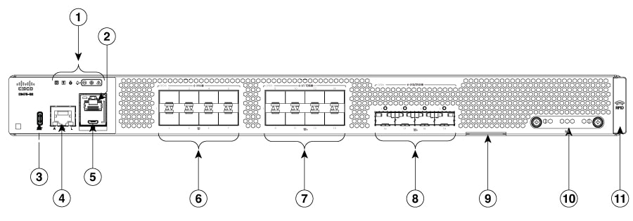

Figure 1. C8475-G2 Chassis - I/O Side
Table 1. I/O Side

1

Status indicator LEDs

2

RJ45 console port

3

USB port

4

Gigabit Ethernet management port

5

Micro-USB console

6

SFP ports (0/0/0-0/0/7)

7

SFP+ ports (0/0/8-0/0/15)

8

SFP28 ports (0/0/16-0/0/19)

9

Device label tray

10

M.2 storage slot

11

RFID (Provisionable)


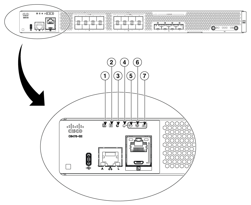
LEDs for C8475-G2 Secure Router

Figure 2. LEDs for C8475-G2 Secure Router

1

Power

2

Status

3

Blue beacon

4

Alarm icon (not lit)

5

Minor alarm

6

Major alarm

7

Critical alarm

Table 2. LEDs Indicators

LED

Color

Description

PSU

Green/Amber

Power Supply Status

Off: The system is powered off.

Amber: A power supply has malfunctioned (or is not installed).

Green: Both installed power supplies are operating correctly.

Status

Green/Amber/Red

System Status

Blinking Amber: The system is booting ROMMON.

Amber: System is at ROMMON prompt or booting router software.

Green: Normal System Operation.

Blinking Red: The system has failed a hardware integrity check.

Beacon

Blue

Beacon LED

Blinking Blue: Beacon requested.

Minor Alarm

Amber

Minor Alarm

Off: No Minor Alarm.

Amber: Minor Alarm Asserted.

Major Alarm

Red

Major Alarm

Off: No Major Alarm.

Red: Major Alarm Asserted.

Critical Alarm

Red

Critical Alarm

Off: No Critical Alarm.

Red: Critical Alarm Asserted.

Link

Green

RJ-45 Management Ethernet Link LED

Off: No link.

Green: Ethernet cable present and link established with other side.

Activity

Green

RJ-45 Management Ethernet Activity LED

Blinking Green: Ethernet activity detected.

USB con

Green

USB Console Active

Green: indicates that the active console port is USB.

When this is “On” the SER CON LED will be “Off”.

SER con

Green

Serial Console Active

Green: indicates that the active console port is RJ-45.

When this is “On” the USB CON LED will be “Off”.

SFP

Green/Amber

SFP port 0/1 Link LED

Off: SFP not present or port not configured (i.e., admin down).

Amber: Link down / Loss of Signal.

Green: Link established.


C8475-G2 summary

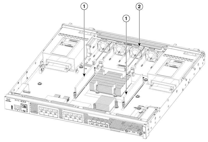
The figure below shows the internal view of C8475-G2 router with parts and module locations.

Figure 3. Summary of C8475-G2

1

DIMMs

2

Fan tray