Hardware Installation Guide for Cisco 8400 Series Secure Routers

PDF

Hardware Installation Guide for Cisco 8400 Series Secure Routers

Remove and replace the battery

Want to summarize with AI?

Log in

Details proper handling, removal, and replacement procedures for batteries, emphasizing safety considerations and compliant disposal of battery units from C8455-G2 and C8475-G2 routers.


These instructions are provided in order to comply with the EU Battery Replaceability Requirement.

  • This product was not specifically designed for battery replacement in the field.

  • It is recommended that, whenever possible, follow the standard repair or return process for battery issues.

Caution

Always wear an ESD-preventive wrist strap and ensure that it makes good contact with your skin when you remove or install the internal modules. Connect the equipment end of the wrist strap to the metal part of the chassis.
Remove the battery

Perform this procedure when the battery requires replacement or maintenance on supported hardware.

Note

Follow proper electrostatic discharge (ESD) precautions before handling the battery or device.

Wear an ESD-preventive wrist strap, ensuring that it makes good skin contact. Connect the clip to an unpainted surface of the chassis frame to channel unwanted ESD voltages safely to ground. To guard against ESD damage and shocks, the wrist strap and cord must operate effectively.

Warning

Statement 1015—Battery Handling

To reduce risk of fire, explosion or leakage of flammable liquid or gas:

  • Replace the battery only with the same or equivalent type recommended by the manufacturer.

  • Do not dismantle, crush, puncture, use sharp tool to remove, short external contacts, or dispose of in fire.

  • Do not use if battery is warped or swollen.

Procedure

1.

Before you perform any module replacement, read the Safety Warnings section and disconnect the power supplies.

2.

Identify the type of battery holder and follow the instructions accordingly.

3.

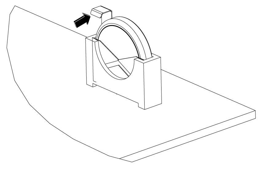
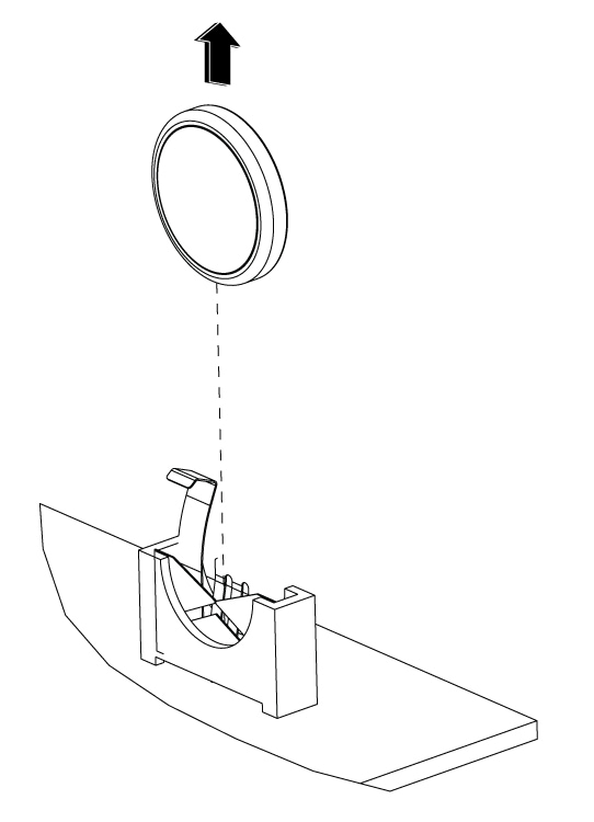
For Battery Holder type 1, follow these instructions to remove the battery:

  1. Pull the retention arm back from the battery.

    Figure 1. Pull back the latch arm
  2. Lift the battery out of the holder.

    Figure 2. Remove the battery
4.

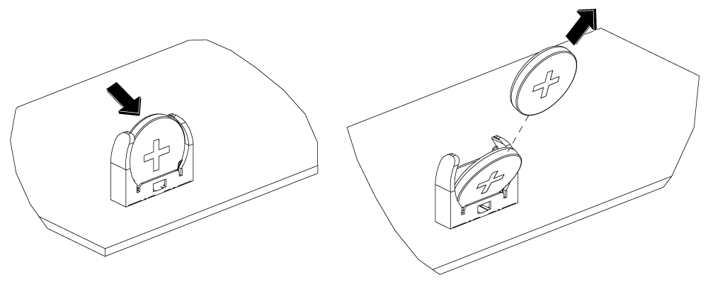
For Battery Holder type 2, follow these instructions to remove the battery:

  1. Pivot the battery in the direction shown.

  2. Pull the battery out at an angle.

    Figure 3. Remove the battery

Replace the battery

Replace the battery in the chassis following the safety procedures to ensure proper device functionality.
Note

Follow proper electrostatic discharge (ESD) precautions before handling the battery or device.

Before you begin

  • There are two types of battery holders that may be present on the PCBA. Identify the correct type and refer to the instructions specific to that type.

  • The battery is a CR2032 type. Batteries should only be replaced with the same or an equivalent type recommended by the manufacturer.

    • RENATA; 100272

    • VARTA MICROBATTERY INC; 06032 101 501

Procedure

1.

Read the Safety Warnings instructions and disconnect the power supplies before you perform any module replacement.

2.

Identify the type of battery holder and follow the instructions accordingly.

3.

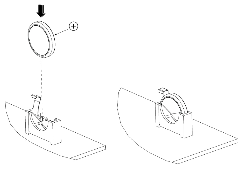
For Battery Holder type 1, follow these instructions to replace the battery:

  1. Orient the battery with positive polarity as shown.

  2. Push the battery down into the holder. Once installed, the latch will snap back over the battery to secure it in place.

    Figure 4. Install the battery
4.

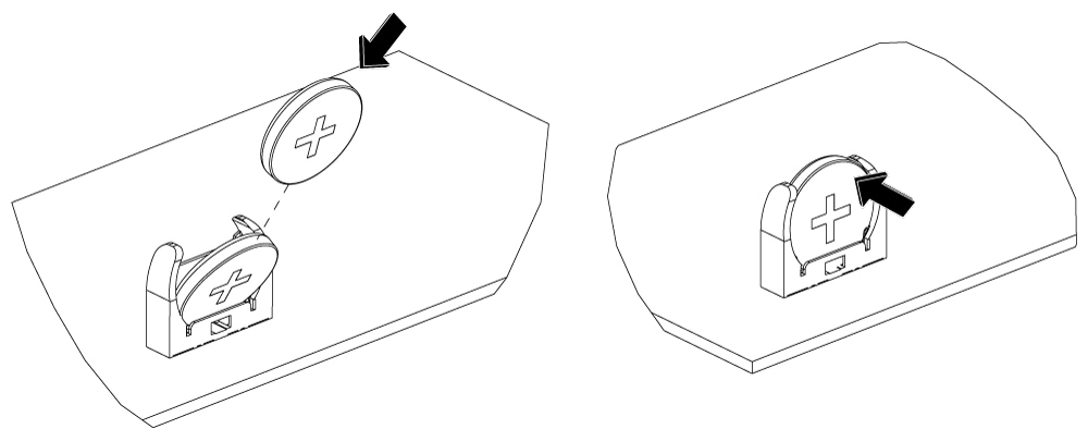
For Battery Holder type 2, follow these instructions to replace the battery:

  1. Orient the battery with positive polarity as shown.

  2. Angle the battery so you can insert the edge of the battery into the holder base.

  3. Rotate the battery and press into the base in the same motion to install the battery firmly in the holder.

Figure 5. Install the battery