Describes procedures for AC/HVDC power supplies, guiding users through installation and removal methods to support multiple power configurations.
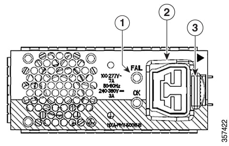
| 1 |
Status LED |
2 |
HVAC/HVDC Socket |
| 3 |
Latch |
Hardware Installation Guide for Cisco 8400 Series Secure Routers
Describes procedures for AC/HVDC power supplies, guiding users through installation and removal methods to support multiple power configurations.
| 1 |
Status LED |
2 |
HVAC/HVDC Socket |
| 3 |
Latch |
Do not install the power supplies with the chassis cover off.
| 1. | Ensure that the chassis power switch on the chassis is in the Standby position.
|
|
| 2. | Insert the power supply module into the appropriate slot(s), making sure that the retention latch is firmly placed. You can verify that the power supply module is firmly latched by gently pulling the power supply handle. |
|
| 3. | Insert the power supply cables firmly into the power supplies.
|
|
| 4. | If you have changed the chassis power switch to the Standby position in Step 1, press the power switch to the On position. The power supply LEDs are illuminated (green). |
| 1. | Ensure that the chassis power switch is in the Standby position.
|
|
| 2. | Unplug the power cable from the power supply. |
|
| 3. | Press the retaining latch towards the pull handle, grasp the handle with one hand, and pull the power supply out of the slot while supporting the weight of the power supply with the other hand. |
|
| 4. | Repeat these steps if it is required to remove the other AC/HVDC power supply. |