Hardware Installation Guide for Cisco 8400 Series Secure Routers

PDF

Hardware Installation Guide for Cisco 8400 Series Secure Routers

DC power supply

Want to summarize with AI?

Log in

Outlines procedures for handling DC power supplies, including installation, removal, wiring the DC input power source, and relevant safety considerations to maintain system power integrity.


This section describes how to install the DC power supply input power that leads to the DC input power supply:

Note

The device has redundant power supplies that can be hot-swapped.

The DC input connector has negative(-) on left and positive(+) on right with mark.

The power supply has a handle to be used for insertion and extraction. The module must be supported with one hand because of its length.
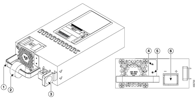
Figure 1. DC power supply

400W DC

1

Handle

2

Strain relief

3

Latch

4

Fail LED

5

Status LED

6 Terminal block


Install DC power supply

Note

Do not install the power supplies with the chassis cover off.

This section describes how to install the DC power supply input power leads to the DC input power supply. Before you begin, read these important notices:

  • The color coding of the DC input power supply leads depends on the color coding of the DC power source at your site. Ensure that the lead color coding you choose for the DC input power supply matches the lead color coding used at the DC power source and verify that the power source is connected to the negative (–) terminal and to the positive (+) terminal on the power supply.

  • Ensure that the chassis ground is connected on the chassis before you begin installing the DC power supply. Follow the steps provided in the Chassis Ground Connection section.

Each DC input power cable is terminated at the PSU by a cable lug, as shown in the following figure.

Note

DC input power cables must be connected to the PSU terminal studs in the proper positive (+) and negative (–) polarity. In some cases, the DC cable leads are labeled, which is a relatively safe indication of the polarity. However, you must verify the polarity by measuring the voltage between the DC cable leads. When making the measurement, the positive (+) lead and the negative (–) lead must always match the (+) and (–) labels on the power distribution unit.

Note

To avoid hazardous conditions, all components in the area where DC input power is accessible must be properly insulated. Therefore, before installing the DC cable lugs, be sure to insulate the lugs according to the manufacturer's instructions.


Remove and replace the DC power supply

The device has redundant power supplies that can be hot-swapped.

This section describes how to remove a DC power supply from C8400 Series Routers

Follow these steps:

Procedure

1.

Read the safety warnings section of this document.

2.

The device has redundant power supplies and does not have to be shut down prior to replacing the power supply. The power supply may be replaced while the device is in service.

3.

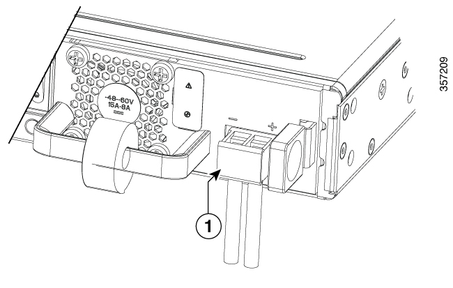
At the power supply unit or at the local circuit breaker, remove the power from the DC power leads (label 1) attached to the power supply to be replaced.

Figure 2. Remove DC power
4.

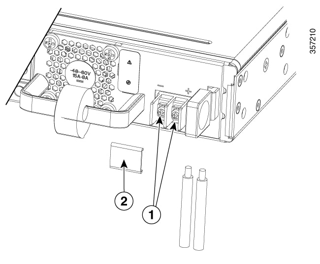
Remove the terminal block cover and loosen the terminal screws (label 1) securing the power cabling. Remove the power cabling from the terminal block.

Figure 3. Remove power cabling
5.

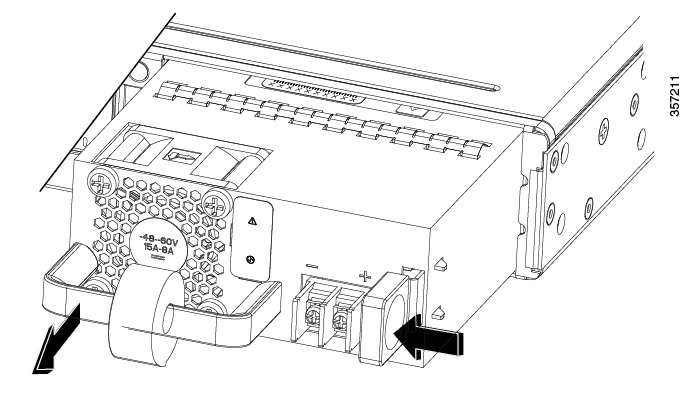
Depress the power supply latch and use the handle to pull the supply out of the device.

Figure 4. Pull out power supply

This completes the procedure for removing a DC power supply.


Wire the DC power

In the Cisco 8400 Series Secure Routers, the DC power supply has a terminal block that is installed into the power supply terminal block header.

Use the following steps to wire the DC input power source:

Procedure

1.

Turn off the circuit breaker from the power source to be connected to the power source.

2.

Insert the power module in the power-supply slot, and gently push it into the slot.

  • The DC power supply (excluding the extraction handle) is flushed with the device.

3.

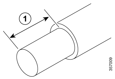
Wire can be stripped and terminated directly to the power supply terminal block, or a crimp style spade terminal lug can be used. If using a terminal lug follow the manufacturer's instructions for terminating the lug to the wire. If terminating directly to the terminal block using bare wire, following the below directions. Use a wire-stripping tool to strip each of the two wires coming from the DC input power source and strip the wires to approximately 0.39 inch (10 mm) + 0.02 inch (0.5 mm). It it recommended that 14 AWG insulated wire be used. Do not strip more than the recommended length of wire because doing so could leave the wire exposed from the terminal block and shows a stripped DC input power source wire.

Figure 5. Stripped DC input power source wire

1

0.39 inch (10 mm) is the recommended wire-strip length for the terminal block.

Warning

An exposed wire lead from a DC input power source can conduct harmful levels of electricity. Be sure that no exposed portion of the DC input power source wire extends from the terminal block. Statement 122

4.

Identify the positive and negative feed positions for the terminal block connection.

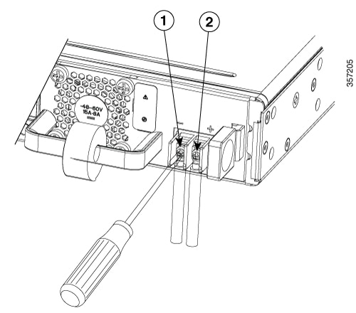
  1. Positive (+) lead wire (right)

  2. Negative (–) lead wire (left)

5.

Remove the terminal block cover.

6.

Insert the exposed wire into the terminal block. Ensure that you cannot see any wire lead outside the plastic cover. Only wires with insulation should extend from the terminal block.

Caution

Do not overtorque the terminal block captive screws. Ensure that the connection is snug, but the wire is not crushed. Verify by tugging lightly on each wire to ensure that they do not move.

7.

Use a screwdriver to tighten the terminal block captive screws.

Figure 6. DC power supply with lead wires

1

Negative (–) lead wire

2

Positive (+) lead wire

8.

Repeat these steps for the remaining DC input power source wire as applicable.

9.

Use a tie wrap to secure the wires to the rack, so that the wires are not pulled from the terminal block by casual contact.

10.

Turn on the circuit breaker at the power source.